
EN
EN
EN
EN
EN
EN
EN
EN
EN
EN
EN
EN
EN
EN
EN
EN
EN
EN
EN
EN
EN
EN
EN
EN
EN
Manual
Additional languages r-stahl.com
EN
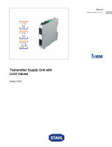
Temperature transmitter Ex i
Series 9182

2
EN
EN
EN
EN
EN
EN
EN
EN
EN
EN
EN
EN
EN
EN
EN
EN
EN
EN
EN
EN
EN
EN
EN
EN
EN
Temperature transmitter Ex i
Series 9182
Contents
1 General Information ............................................................................................3
1.1 Manufacturer .......................................................................................................3
1.2 Information about the Manual .............................................................................3
1.3 Further Documents .............................................................................................3
1.4 Conformity with Standards and Regulations .......................................................3
2 Explanation of the Symbols ................................................................................4
2.1 Symbols used in this Manual ..............................................................................4
2.2 Warning Notes ....................................................................................................4
2.3 Symbols on the Device .......................................................................................5
3 Safety Notes .......................................................................................................5
3.1 Storage of the Manual .........................................................................................5
3.2 Personnel Qualification .......................................................................................5
3.3 Safe Use .............................................................................................................6
3.4 Modifications and Alterations ..............................................................................7
4 Function and Device Design ...............................................................................7
4.1 Function ..............................................................................................................7
4.2 Device Design .....................................................................................................8
5 Technical Data ....................................................................................................9
6 Engineering .......................................................................................................18
7 Transport and Storage ......................................................................................18
8 Mounting and Installation ..................................................................................19
8.1 Dimensions / Fastening Dimensions .................................................................19
8.2 Mounting / Dismounting, Operating Position .....................................................20
8.3 Installation .........................................................................................................23
9 Parameterization and Commissioning ..............................................................28
9.1 Replacement of the Device ...............................................................................28
9.2 Parameterizations .............................................................................................28
9.3 Commissioning .................................................................................................35
10 Operation ..........................................................................................................35
10.1 Operation ..........................................................................................................35
10.2 Indications .........................................................................................................35
10.3 Troubleshooting ................................................................................................36
11 Maintenance, Overhaul, Repair ........................................................................36
11.1 Maintenance .....................................................................................................36
11.2 Overhaul ...........................................................................................................37
11.3 Repair ...............................................................................................................37
11.4 Returning the Device ........................................................................................37
12 Cleaning ............................................................................................................38
13 Disposal ............................................................................................................38
14 Accessories and Spare Parts ...........................................................................38

9182602330
2023‐04‐11·HB00·III·en·03
General Information
3
EN
EN
EN
EN
EN
EN
EN
EN
EN
EN
EN
EN
EN
EN
EN
EN
EN
EN
EN
EN
EN
EN
EN
EN
EN
Temperature transmitter Ex i
Series 9182
1 General Information
1.1 Manufacturer
R. STAHL Schaltgeräte GmbH
Am Bahnhof 30
74638 Waldenburg
Germany
Phone: +49 7942 943-0
Fax: +49 7942 943-4333
Internet: r-stahl.com
E-Mail: [email protected]
1.2 Information about the Manual
ID-No.: 9182602330
Publication Code: 2023‐04‐11·HB00·III·en·03
Hardware version: C, C/1
Software version: 01-09 or higher
The original manual is the English edition.
They are legally binding in all legal affairs.
1.3 Further Documents
• Cabinet installation guide
• Brief instructions for module parameterising with ISpac Wizard
(see ISpac Wizard software)
• FMEDA reports "STAHL 07/07-23 R016" and "STAHL 07/07-23 R017"
• Safety manual 9182 Ex i
• Data sheet 9182 Ex i
• Operating instructions 9182 Ex i
•National information and documents relating to use in hazardous areas
(see also chapter 1.4)
For documents in additional languages, see r-stahl.com.
1.4 Conformity with Standards and Regulations
IECEx, ATEX, EU Declaration of Conformity and further national certificates and
documents can be downloaded via the following link:
https://r-stahl.com/en/global/support/downloads/
Depending on the scope of validity, additional Ex-relevant information may be attached.
IECEx is also available at: https://www.iecex.com/

Explanation of the Symbols
49182602330
2023‐04‐11·HB00·III·en·03
EN
EN
EN
EN
EN
EN
EN
EN
EN
EN
EN
EN
EN
EN
EN
EN
EN
EN
EN
EN
EN
EN
EN
EN
EN
Temperature transmitter Ex i
Series 9182
2 Explanation of the Symbols
2.1 Symbols used in this Manual
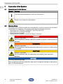
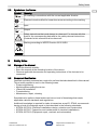
2.2 Warning Notes
Warnings must be observed under all circumstances, in order to minimize the risk due to
construction and operation. The warning notes have the following structure:
• Signalling word: DANGER, WARNING, CAUTION, NOTICE
• Type and source of danger/damage
• Consequences of danger
• Taking countermeasures to avoid the danger or damage
Symbol Meaning
Tips and recommendations on the use of the device
Danger due to explosive atmosphere
DANGER
Danger to persons
Non-compliance with the instruction results in severe or fatal injuries to
persons.
WARNING
Danger to persons
Non-compliance with the instruction can result in severe or fatal injuries
to persons.
CAUTION
Danger to persons
Non-compliance with the instruction can result in light injuries to
persons.
NOTICE
Avoiding material damage
Non-compliance with the instruction can result in material damage to the device
and / or its environment.

9182602330
2023‐04‐11·HB00·III·en·03
Safety Notes
5
EN
EN
EN
EN
EN
EN
EN
EN
EN
EN
EN
EN
EN
EN
EN
EN
EN
EN
EN
EN
EN
EN
EN
EN
EN
Temperature transmitter Ex i
Series 9182
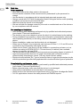
2.3 Symbols on the Device
3 Safety Notes
3.1 Storage of the Manual
• Read the manual carefully.
• Store the manual at the mounting location of the device.
• Observe applicable documents and operating instructions of the devices to be
connected.
3.2 Personnel Qualification
Qualified specialist personnel are required to perform the tasks described in this manual.
This primarily applies to work in the following areas:
• Project engineering
• Mounting/dismounting the device
• (Electrical) installation
• Commissioning
• Maintenance, repair, cleaning
Specialists who perform these tasks must have a level of knowledge that meets
applicable national standards and regulations.
Additional knowledge is required for tasks in hazardous areas! R. STAHL recommends
having a level of knowledge equal to that described in the following standards:
• IEC/EN 60079-14 (Electrical installations design, selection and construction)
• IEC/EN 60079-17 (Inspection and maintenance of electrical installations)
• IEC/EN 60079-19 (Equipment repair, overhaul and reclamation)
Symbol Meaning
05594E00
CE marking in accordance with the current applicable directive.
02198E00
Electrical circuit certified for hazardous areas according to the marking.
15649E00
Input
15648E00
Output
11048E00
Safety instructions that must always be observed: For devices with this
symbol, the corresponding data and/or the safety-relevant instructions
contained in this manual must be observed!
20690E00
Marking according to WEEE Directive 2012/19/EU

Safety Notes
69182602330
2023‐04‐11·HB00·III·en·03
EN
EN
EN
EN
EN
EN
EN
EN
EN
EN
EN
EN
EN
EN
EN
EN
EN
EN
EN
EN
EN
EN
EN
EN
EN
Temperature transmitter Ex i
Series 9182
3.3 Safe Use
Before assembly
• Read and observe the safety notes in this manual.
• Ensure that the contents of this manual are fully understood by the personnel in
charge.
• Use the device in accordance with its intended and approved purpose only.
• Always consult with R. STAHL Schaltgeräte GmbH if using the device under operating
conditions not covered by the technical data.
• Make sure that the device is not damaged.
• We are not liable for damage caused by incorrect or unauthorised use of the device or
by non-compliance with this manual.
For mounting and installation
• Have mounting and installation performed only by qualified and authorised persons
(see chapter "Personnel qualification").
• The device is only to be installed in areas for which it is suited based on its marking.
• During installation and operation, observe the information (characteristic values and
rated operating conditions) on the rating, data and information plates located on the
device.
• Before installation, make sure that the device is not damaged.
• When used in Zones 2, the intrinsically safe devices of Zones 1, 0, 21 and 20 can be
connected to the intrinsically safe signal circuits.
• When used in Zone 2, the device is to be installed in a protective enclosure or in a
cabinet according to IEC/EN 60079-0. This enclosure (or cabinet) has a suitable
degree of protection (at least IP54).
• The device may only be operated in environments not exceeding degree of pollution 2.
• Interconnecting several devices in a single intrinsically safe circuit can result in
different safety characteristic values. This may impair intrinsic safety!
• Electrical circuits with the "Ex i" type of protection can no longer be operated as circuits
with this protection type after being operated with circuits with other types of protection.
Commissioning, maintenance, repair
• Only have commissioning and repairs performed by qualified and authorised persons
(see chapter "Personnel qualification").
• Before commissioning, make sure that the device is not damaged.
• Only perform maintenance work described in this manual.
• Repair work on the devices must be performed only by R.STAHL Schaltgeräte GmbH.
• For SIL applications observe the safety manual and FMEDA reports.

9182602330
2023‐04‐11·HB00·III·en·03
Function and Device Design
7
EN
EN
EN
EN
EN
EN
EN
EN
EN
EN
EN
EN
EN
EN
EN
EN
EN
EN
EN
EN
EN
EN
EN
EN
EN
Temperature transmitter Ex i
Series 9182
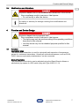
3.4 Modifications and Alterations
4 Function and Device Design
4.1 Function
Application range
The temperature transmitter is used for intrinsically safe operation of temperature
sensors or resistance transmitters. Virtually all conventional sensors, such as Pt100,
Pt500, thermocouples and potentiometers, can be connected.
Mode of operation
The parameters of the device can be adjusted using the ISpac Wizard software or
alternatively by means of a DIP switch (only with Type 9182/.0-5.-11).
DANGER
Explosion hazard due to modifications and alterations to the device!
Non-compliance results in severe or fatal injuries.
• Do not modify or alter the device.
No liability or warranty for damage resulting from modifications and
alterations.
DANGER
Explosion hazard due to improper use!
Non-compliance results in severe or fatal injuries.
• The device may only be used according to the operating conditions
described in this manual.
• Use the device only for the intended purpose specified in this
manual.

Function and Device Design
89182602330
2023‐04‐11·HB00·III·en·03
EN
EN
EN
EN
EN
EN
EN
EN
EN
EN
EN
EN
EN
EN
EN
EN
EN
EN
EN
EN
EN
EN
EN
EN
EN
Temperature transmitter Ex i
Series 9182
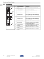
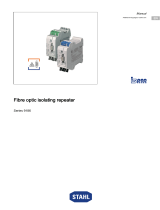
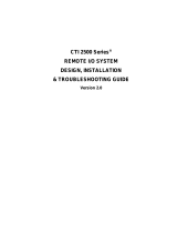
4.2 Device Design
# Device component Description
07451E00
1 Black/
green terminals
Connection terminals for the safe area
2 "PWR" LED, green Auxiliary power indication
3 "LF1" LED, red Indication of line fault detection for
channel 1
4 "LF2" LED, red Indication of line fault detection for
channel 2
5 DIP switch "LF1" Reset activation of the line fault detection
and anti-pumping device of the limiting
value for channel 1
6 DIP switch "ADJ1" Adjustment of line resistance in channel 1
7 DIP switch "LF2" Reset activation of the line fault detection
and anti-pumping device of the limiting
value for channel 2
8 DIP switch "ADJ2" Adjustment of line resistance in channel 2
9 Blue terminals Connection terminals for the hazardous
area (intrinsically safe Ex i)
10 Parameterization
interface
Configuration of the device by means of
ISpac Wizard software Type "9199"
11 "A" and "B" LED,
yellow
Indication for limit contacts for channel 1
18 "A" and "B" LED,
yellow
Indication for limit contacts for channel 2
1
9
2
5
7
4
3
6
8
10
11
18
9182

9182602330
2023‐04‐11·HB00·III·en·03
Technical Data
9
EN
EN
EN
EN
EN
EN
EN
EN
EN
EN
EN
EN
EN
EN
EN
EN
EN
EN
EN
EN
EN
EN
EN
EN
EN
Temperature transmitter Ex i
Series 9182
5 Technical Data
Marking
Type designation 9182/.0-5.-1.
CE marking C0158
Explosion Protection
Version for all types 9182/.0-5.-1.
Global (IECEx)
Gas and dust IECEx BVS 09.0046X
Ex ec nC [ia Ga] IIC T4 Gc
[Ex ia Da] IIIC
Europe (ATEX)
Gas and dust DMT 02 ATEX E 243 X
E II 3 (1) G Ex ec nC [ia Ga] IIC T4 Gc
E II (1) D [Ex ia Da] IIIC
Certifications and certificates
Certificates IECEx, ATEX, Brazil (ULB), EAC, India (PESO), Canada (cFM),
Korea (KTL), USA (FM, UL)
Ship approval DNV (EU RO Mutual Recognition), CCS
Safety data
Max. voltage Uo6.5 V
Max. current Io19.7 mA
Max. power Po32 mW (linear characteristic)
Max. connectable
capacitance Co
IIC 25 mF
IIB 570 mF
Max. connectable
inductance Lo
IIC 90 mH
IIB 330 mH
Internal
capacitance Ci
negligible
Internal inductance Linegligible
Safety-related
maximum voltage
253 V

Technical Data
10 9182602330
2023‐04‐11·HB00·III·en·03
EN
EN
EN
EN
EN
EN
EN
EN
EN
EN
EN
EN
EN
EN
EN
EN
EN
EN
EN
EN
EN
EN
EN
EN
EN
Temperature transmitter Ex i
Series 9182
Explosion Protection
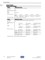
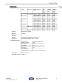
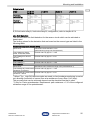
Functional safety (IEC 61508)
Version 9182/10-51-13, SIL 2
Test report Exida FMEDA Stahl 07/07-23-R016
Max. SIL 2
Safe Failure Fraction
SFF
78%
MTBF 120 years
PFDAVG at T[Proof]
Further information see safety manual and test report
Version 9182/10-51-14, SIL 2
Test report Exida STAHL 07/07-23 R016 and STAHL 07/07-23 R017
Max. SIL 2
Safe Failure Fraction
SFF
MTBF
PFDAVG at T[Proof]
Further information see safety manual and test report
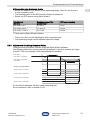
T[Proof] 1 year 3 years 5 years 10 years
PFDAVG 1.31 x 10⁻³ 2.54 x 10⁻³ 3.77 x 10⁻³ 6.86 x 10⁻³
4 to 20 mA Limit contact Parallel limit contact
78% 78.4% 81.1%
4 to 20 mA Limit contact Parallel limit contact
120 years 114 years 114 years
4 to 20 mA Limit contact Parallel limit contact
1 year 1.31 x 10⁻³ 1.14 x 10⁻³ 9.72 x 10⁻⁴
2 years 2.54 x 10⁻³ 2.22 x 10⁻³ 1.89 x 10⁻³
5 years 3.77 x 10⁻³ 3.30 x 10⁻³ 2.80 x 10⁻³
10 years 6.86 x 10⁻³ 5.99 x 10⁻³ 5.09 x 10⁻³

9182602330
2023‐04‐11·HB00·III·en·03
Technical Data
11
EN
EN
EN
EN
EN
EN
EN
EN
EN
EN
EN
EN
EN
EN
EN
EN
EN
EN
EN
EN
EN
EN
EN
EN
EN
Temperature transmitter Ex i
Series 9182
Technical Data
Version for all types 9182/.0-5.-1.
Electrical data
Auxiliary power
Nominal voltage
UN
24 V DC
Voltage range 18 to 31.2 V
Residual ripple
within voltage
range
( 3.6 VSS
Nominal current
at UN
1 channel 70 mA
2 channels 80 mA
Power
consumption at UN
( 1.9 W
Power dissipation
at UN
( 1.9 W
Polarity reversal
protection
yes
Operation
indication
LED green "PWR"
Undervoltage
monitoring
yes (no faulty devices / output states)
Galvanic separation
Test voltages
acc. to standard EN 60079-11
Ex i input to
output
1.5 kV AC
Ex i input to
auxiliary power
1.5 kV AC
Ex i input to
configuration
interface
1.5 kV AC
Ex i input to
error message
contact
1.5 kV AC
acc. to standard EN 50178
Output to
auxiliary power
350 V AC
Output to
configuration
interface
350 V AC
Outputs
interconnected
350 V AC
Error message
contact to
auxiliary power
and outputs
350 V AC

Technical Data
12 9182602330
2023‐04‐11·HB00·III·en·03
EN
EN
EN
EN
EN
EN
EN
EN
EN
EN
EN
EN
EN
EN
EN
EN
EN
EN
EN
EN
EN
EN
EN
EN
EN
Temperature transmitter Ex i
Series 9182
Ex i inputs
At
thermocouples
20 V
Configuration
Interface
Version RS232-C
Software ISpac Wizard 9199
Connection 4-pole plug on the front
Settings all device functions and diagnostics
Version 9182/.0-5.-11
Switch
Version 12 + 4-pole DIP switches
Settings Pt100; thermocouple B, E, J, K, N, R, T
each with approx. 90 measuring ranges (°C + °F)
Pt100 in 2-, 3- or 4-wire connection
Output signal 0/4 to 20 mA
Line fault monitoring activated / deactivated
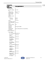
Version for all types 9182/.0-5.-1.
Ex i Input The input parameters can be set via parameterising software ISpac Wizard or
DIP switch.
Input for resistance
temperature detector
Type of circuit 2-, 3-, 4-wire circuit
Linearity temperature / resistance
Measuring current ( 0.25 mA
Max. line resistor
each core
50 Ω (2-wire connection)
100 Ω (3-, 4-wire connection)
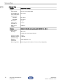
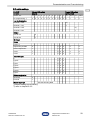
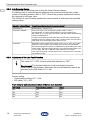
Technical Data
Types Standard Basic measuring
range
Min.
measu-
ring
range
Medium
resolu-
tion
Medium
measure-
ment
error
Pt100
Pt500
Pt1000
IEC 60751 -200 to +850 °C 50 K 0.1 K 0.35 K
Pt250 IEC 60751 -200 to +850 °C 40 K 0.1 K 0.5 K
Pt2000 IEC 60751 -200 to +850 °C 40 K 0.1 K 0.35 K
Ni100
Ni500
Ni1000
DIN 43760 -60 to +180 °C 31 K 0.1 K 0.25 K
Pt100 GOST
6651-94
-200 to +1100 °C 40 K 0.1 K 0.7 K
M50 GOST
6651-94
-200 to +200 °C 70 K 0.1 K 0.7 K
M53 GOST
6651-94
0 to +120 °C 70 K 0.1 K 0.5 K
M100 GOST
6651-94
-200 to +200 °C 40 K 0.1 K 0.45 K

9182602330
2023‐04‐11·HB00·III·en·03
Technical Data
13
EN
EN
EN
EN
EN
EN
EN
EN
EN
EN
EN
EN
EN
EN
EN
EN
EN
EN
EN
EN
EN
EN
EN
EN
EN
Temperature transmitter Ex i
Series 9182
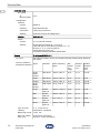
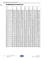
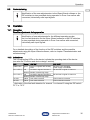
Technical Data
Input thermocouple
Linearity temperature / voltage
Max. line
resistance
per loop
( 1000 O
External
references
Pt100 2-wire connection (-40 to +85 °C)
Constant temperature (-40 to +85 °C)
Potentiometer input
*) with parallel 10 kΩ shunt, no open-circuit monitoring
Circuit type 3-wire connection
Measuring current ( 0.25 mA
Types Standard Basic measuring
range
Min.
measu-
ring
range
Medium
resolu-
tion
Medium
measure-
ment
error
B IEC 60584 +250 to +1800 °C 314 K 0.1 K 1.2 K
E -200 to +1000 °C 36 K 0.1 K 0.2 K
J -200 to +1200 °C 42 K 0.1 K 0.2 K
K -200 to +1370 °C 63 K 0.1 K 0.3 K
N -200 to +1300 °C 75 K 0.1 K 0.3 K
R -50 to +1767 °C 171 K 0.1 K 0.7 K
S -50 to +1767 °C 185 K 0.1 K 0.8 K
T -200 to +400 °C 60 K 0.1 K 0.3 K
L DIN 43710 -200 to +900 °C 55 K 0.1 K 0.3 K
U -200 to +600 °C 48 K 0.1 K 0.3 K
XK GOST -200 to +800 °C 50 K 0.1 K 0.2 K
Potentiometer
resistance range
Average measurement
fault
50 to 500 Ω 0.1 Ω
0.5 to 5 kΩ 1 Ω
1 to 10 kΩ 2 Ω
10 to 100 kΩ *) –

Technical Data
14 9182602330
2023‐04‐11·HB00·III·en·03
EN
EN
EN
EN
EN
EN
EN
EN
EN
EN
EN
EN
EN
EN
EN
EN
EN
EN
EN
EN
EN
EN
EN
EN
EN
Temperature transmitter Ex i
Series 9182
Technical Data
Version 9182/10-51-14, SIL 2
Output
Output signal 0/4 to 20 mA (configurable)
Functional range 0 to 21 mA
Connectable load
resistance RL
1 channel 0 to 750 O
2 channels 0 to 600 O
Resolution ( 1 mA
Settling time
(10 to 90 %)
( 35 ms
Delay input -
output
( 500 ms
Version 9182/.0-50-12 with limit contact and 9182/10-51-14, SIL 2
Limiting values
Message 2 NO / NC
(configurable using ISpac Wizard)
Switching voltage ( ±30 V
Switching current
(resistive load)
( 100 mA
Switch on
resistance
( 2.5 O (typical < 1 O)
Reclosing lockout Reset using the DIP switch or "Power-Off" (configurable)

9182602330
2023‐04‐11·HB00·III·en·03
Technical Data
15
EN
EN
EN
EN
EN
EN
EN
EN
EN
EN
EN
EN
EN
EN
EN
EN
EN
EN
EN
EN
EN
EN
EN
EN
EN
Temperature transmitter Ex i
Series 9182
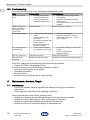
Technical Data
Version for all types 9182/.0-5.-1.
Error detection
Ex i input
Open circuit for resistance thermometers, thermocouples and resistance transmitters
> 1 kO
Short-circuit for resistance thermometers with temperature linearisation and resistance
transmitters
Behaviour of the
output
2.4 mA (configurable 0 to 23 mA or "hold last value")
Settings
(switch LF)
activated / deactivated (only 9182/.0-51-11, 9182/10-51-14, 9182/.0-50-12)
Error detection LED red "LF"
Message of line
fault and auxiliary
power failure
- contact (30 V / 100 mA) closed to earth in case of error
- pac-Bus, potential-free contact (30 V / 100 mA)
Error limits
Accuracy, typical data expressed as % of the basic measuring range at
UN, 23 °C
Middle
measurement
error
( 0.1 %
Temperature
influence
( 0.1 % / 10 K
Electromagnetic
compatibility
Tested under the following standards and regulations:
EN 61326-1 Use in industrial environment;
NAMUR NE 21
Ambient conditions
Ambient temperature
Single device -20 to +70 °C
Group assembly -20 to +60 °C
The installation conditions affect the ambient temperature.
Observe the "Cabinet installation guide"
Storage temperature -40 to +80 °C
Relative humidity
(no condensation)
( 95 %
Use at the height of < 2000 m

Technical Data
16 9182602330
2023‐04‐11·HB00·III·en·03
EN
EN
EN
EN
EN
EN
EN
EN
EN
EN
EN
EN
EN
EN
EN
EN
EN
EN
EN
EN
EN
EN
EN
EN
EN
Temperature transmitter Ex i
Series 9182
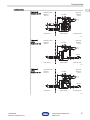
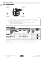
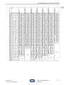
Electrical connection
Configuration input
Connection diagram
Technical Data
Thermocouple Resistance temperature detector Poten-
tiometer
Reference
junction
2-wire 3-wire 4-wire
(1 chan-
nel)
4-wire
(2 chan-
nels)
3-wire
Const.
temp.
ext.
Pt100
Channel
2
09754E00
09755E00
09756E00 09757E00
07110E00 06525E00
15729E00
Channel
1
09759E00 09760E00 09761E00 15730E00
*) Connection of two sensors using 4-wire technology requires an
additional external terminal X1
13
14
15
12
10
11
1 channel,
active
9182/10-51-11
06714E01
pac-Bus
passive
Field Device ISpac Isolator Control System
Division 1
Zone 0 / 1
Division 2
Zone 2
Hazardous area Safe area
2 channels,
active
9182/20-51-11
06724E01
Field Device ISpac Isolator Control System
Division 1
Zone 0 / 1
Division 2
Zone 2
passive
passive
Hazardous area Safe area
pac-Bus

9182602330
2023‐04‐11·HB00·III·en·03
Technical Data
17
EN
EN
EN
EN
EN
EN
EN
EN
EN
EN
EN
EN
EN
EN
EN
EN
EN
EN
EN
EN
EN
EN
EN
EN
EN
Temperature transmitter Ex i
Series 9182
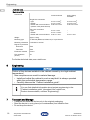
Technical Data
2 channels
9182/20-50-12
06728E01
Field Device ISpac Isolator Control System
Division 1
Zone 0 / 1
Division 2
Zone 2
pac-Bus
Hazardous area Safe area
1 channel,
active
9182/10-51-13
06714E01
pac-Bus
passive
Field Device ISpac Isolator Control System
Division 1
Zone0/1
Division 2
Zone 2
Hazardous area Safe area
1 channel,
active
9182/10-51-14
06726E01
Field Device ISpac Isolator Control System
Division 1
Zone 0 / 1
Division 2
Zone 2
pac-Bus
passive
Hazardous area Safe area

Engineering
18 9182602330
2023‐04‐11·HB00·III·en·03
EN
EN
EN
EN
EN
EN
EN
EN
EN
EN
EN
EN
EN
EN
EN
EN
EN
EN
EN
EN
EN
EN
EN
EN
EN
Temperature transmitter Ex i
Series 9182
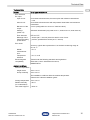
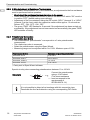
For further technical data, see r-stahl.com.
6 Engineering
7 Transport and Storage
• Transport and store the device only in the original packaging.
• Store the device in a dry place (no condensation) and vibration-free.
• Do not drop the device.
Mechanical data
Connection
Weight approx. 160 g
Mounting type on DIN rail (NS35/15, NS35/7.5) or in pac-Carrier
Mounting orientation horizontal or vertical
Degree of protection
Enclosure IP30
Terminals IP20
Enclosure material PA 6.6
Fire resistance
(UL 94)
V0
NOTICE
Failure of the devices installed in the cabinet caused by too high ambient
temperature!
Non-compliance can result in material damage.
• Install and adjust the cabinet in such a way that it is always operated
within the permissible temperature range.
• Carefully observe the "Cabinet installation guide".
You can find detailed information about project engineering in the
"Cabinet installation guide" (download from r-stahl.com,
Product documentation, subitem "Engineering").
Technical Data
Screw terminals Spring clamp
terminals
Single-wire connection
- rigid
- flexible
- flexible with core end sleeve
- (without / with plastic sleeve)
0.2 to 2.5 mm2
0.2 to 2.5 mm2
0.25 to 2.5 mm2
0.2 to 2.5 mm2
0.2 to 2.5 mm2
0.25 to 2.5 mm2
Two-core connection
- rigid
- flexible
- flexible with core end sleeve
0.2 to 1 mm2
0.2 to 1.5 mm2
0.25 to 1 mm2
–
–
0.5 to 1 mm2

9182602330
2023‐04‐11·HB00·III·en·03
Mounting and Installation
19
EN
EN
EN
EN
EN
EN
EN
EN
EN
EN
EN
EN
EN
EN
EN
EN
EN
EN
EN
EN
EN
EN
EN
EN
EN
Temperature transmitter Ex i
Series 9182
8 Mounting and Installation
The device is approved for use in hazardous areas of Zone 2 with potentially explosive
gas as well as in safe areas.
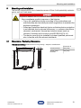
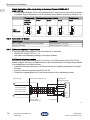
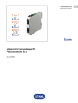
8.1 Dimensions / Fastening Dimensions
DANGER
Explosion hazard due to incorrect installation of the device!
Non-compliance results in severe or fatal injuries.
• Carry out installation strictly according to the instructions and
national safety and accident prevention regulations to maintain the
explosion protection.
• Select and install the electrical device so that explosion protection
is not affected due to external influences, i.e. pressure conditions,
chemical, mechanical, thermal and electric impact such as
vibration, humidity and corrosion (see IEC/EN 60079-14).
• The device must only be installed by trained qualified personnel
who is familiar with the relevant standards.
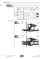
Dimensional drawings (all dimensions in mm [inches]) – Subject to modifications
09685E00
X
122 4 80[, ]
114,5 4 51[, ]
99 3 90[, ] 17,6 [0,69]
Dimension X
Screw terminals 108 [4.25]
Spring clamp
terminals
128 [5.04]

Mounting and Installation
20 9182602330
2023‐04‐11·HB00·III·en·03
EN
EN
EN
EN
EN
EN
EN
EN
EN
EN
EN
EN
EN
EN
EN
EN
EN
EN
EN
EN
EN
EN
EN
EN
EN
Temperature transmitter Ex i
Series 9182
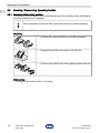
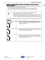
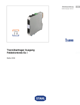
8.2 Mounting / Dismounting, Operating Position
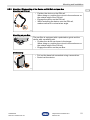
8.2.1 Mounting / Dismounting pac-Bus
The pac-Bus is an accessory which facilitates wiring of the auxiliary power and reading
out of the collective error message.
Mounting
Dismounting
• Proceed in the reverse order to mounting.
The components for the pac-Bus Type 9194 must be ordered separately.
07392E00
• Connect the required number of pac-Bus elements.
07391E00
• Engage the pac-Bus elements on the DIN rail.
15551E00
• Connect the terminal set at the beginning and at the end.
Page is loading ...
Page is loading ...
Page is loading ...
Page is loading ...
Page is loading ...
Page is loading ...
Page is loading ...
Page is loading ...
Page is loading ...
Page is loading ...
Page is loading ...
Page is loading ...
Page is loading ...
Page is loading ...
Page is loading ...
Page is loading ...
Page is loading ...
Page is loading ...
-
 1
1
-
 2
2
-
 3
3
-
 4
4
-
 5
5
-
 6
6
-
 7
7
-
 8
8
-
 9
9
-
 10
10
-
 11
11
-
 12
12
-
 13
13
-
 14
14
-
 15
15
-
 16
16
-
 17
17
-
 18
18
-
 19
19
-
 20
20
-
 21
21
-
 22
22
-
 23
23
-
 24
24
-
 25
25
-
 26
26
-
 27
27
-
 28
28
-
 29
29
-
 30
30
-
 31
31
-
 32
32
-
 33
33
-
 34
34
-
 35
35
-
 36
36
-
 37
37
-
 38
38


Ask a question and I''ll find the answer in the document
Finding information in a document is now easier with AI
Related papers
-
 Stahl 9162 Operating instructions
-
 Stahl 6036 Operating instructions
-
 Stahl ORCA01 Operating instructions
-
 Stahl 9186 Operating instructions
-
 Stahl 9193 Operating instructions
-
 Stahl 9160 Operating instructions
-
 Stahl 9195 Operating instructions
-
 Stahl 9165 Operating instructions
-
 Stahl 9180 Operating instructions
-
Stahl 253021 Installation guide


Other documents
-
Novus TxRail-USB User manual
-
BRONKHORST mini CORI-FLOW Ex d User manual
-
itsensor TXMINI-DIN43650 User manual
-
Seneca Z-4RTD2-SI User manual
-
INOR Programmable Temperature Transmitter Operating instructions
-
ABB ACS 600 MultiDrive User manual
-
BDI LINQ 9181 User manual
-
 Control Technology CTI 2500 Series Design, Installation & Troubleshooting Manual
-
ADLINK Technology ACLD-9182 User manual
-
B&K Precision 9171 User manual
