Page is loading ...

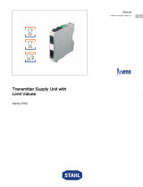
Fibre optic isolating repeater
Series 9186
Manual
Additional languages r-stahl.com
DE
EN
FR
IT
ES
RU
NL
DK
SE
FI
PT
GR
PL
CZ
SK
HU
SL
RO
BG
LV
LT
EE
CH
KR
CN

Contents
2
DE
EN
FR
IT
ES
RU
NL
DK
SE
FI
PT
GR
PL
CZ
SK
HU
SL
RO
BG
LT
EE
CH
KR
CN
Fibre optic isolating repeater
Series 9186
Contents
1 General Information .............................................................................................3
1.1 Manufacturer........................................................................................................3
1.2 Information about this Manual..............................................................................3
1.3 Further Documents ..............................................................................................3
1.4 Conformity with Standards and Regulations........................................................3
2 Explanation of Symbols .......................................................................................4
2.1 Symbols used in this Manual ...............................................................................4
2.2 Warning Notes .....................................................................................................4
2.3 Symbols on the Device ........................................................................................5
3 Safety Notes ........................................................................................................5
3.1 Storage of the Manual..........................................................................................5
3.2 Personnel Qualification ........................................................................................5
3.3 Safe Use ..............................................................................................................6
3.4 Modifications and Alterations...............................................................................8
4 Function and Device Design................................................................................8
4.1 Function ...............................................................................................................8
4.2 Device Design......................................................................................................9
5 Technical Data...................................................................................................11
6 Project Engineering............................................................................................16
6.1 PROFIBUS.........................................................................................................17
6.2 Modbus/ServiceBus...........................................................................................19
6.3 PROFIsafe .........................................................................................................21
7 Transport and Storage.......................................................................................22
8 Mounting and Installation...................................................................................22
8.1 Dimensions/Fastening Dimensions....................................................................23
8.2 Mounting/Dismounting, Operating Position........................................................24
8.3 Installation..........................................................................................................25
9 Parameterisation and Commissioning ...............................................................30
9.1 Replacing the Device.........................................................................................30
9.2 Parameterisation................................................................................................31
10 Operation ...........................................................................................................34
10.1 Operation ...........................................................................................................34
10.2 Indicators ...........................................................................................................34
10.3 Troubleshooting .................................................................................................35
11 Maintenance, Overhaul, Repair .........................................................................35
11.1 Maintenance ......................................................................................................35
11.2 Maintenance ......................................................................................................35
11.3 Repair ................................................................................................................36
11.4 Returning the Device .........................................................................................36
12 Cleaning.............................................................................................................36
13 Disposal .............................................................................................................36
14 Accessories and Spare Parts.............................................................................37

918660330020
2023-10-20·HB00·III·en·02
General Information
3
DE
EN
FR
IT
ES
RU
NL
DK
SE
FI
PT
GR
PL
CZ
SK
HU
SL
RO
BG
LV
LT
EE
CH
KR
CN
Fibre optic isolating repeater
Series 9186
1 General Information
1.1 Manufacturer
1.2 Information about this Manual
The original manual is the German edition.
This is legally binding in all legal affairs.
1.3 Further Documents
• Data sheet
• Operating instructions
• National information and documents relating to use in hazardous areas
(see also chapter 1.4)
For documents in other languages, see r-stahl.com.
1.4 Conformity with Standards and Regulations
IECEx, ATEX, EU Declaration of Conformity and further national certificates and
documents can be downloaded via the following link:
https://r-stahl.com/en/global/support/downloads/
Depending on the scope of validity, additional Ex-relevant information may be attached.
IECEx is also available at: https://www.iecex.com/
R. STAHL Schaltgeräte GmbH
Am Bahnhof 30
74638 Waldenburg
Germany
Tel.:
Fax:
Internet:
E-mail:
+49 7942 943-0
+49 7942 943-4333
r-stahl.com
info@r-stahl.com
ID no.: 918660330020
Publication code: 2023-10-20·HB00·III·en·02
Hardware version: 20 (type 9186/12); 12 (type 9186/.5)
Software version: 122 (type 9186/12); 130 (type 9186/.5)

Explanation of Symbols
4918660330020
2023-10-20·HB00·III·en·02
DE
EN
FR
IT
ES
RU
NL
DK
SE
FI
PT
GR
PL
CZ
SK
HU
SL
RO
BG
LV
LT
EE
CH
KR
CN
Fibre optic isolating repeater
Series 9186
2 Explanation of Symbols
2.1 Symbols used in this Manual
2.2 Warning Notes
Warning notes must be observed under all circumstances, in order to minimise the risk
resulting from design engineering and operation. The warning notes have the following
structure:
• Signalling word: DANGER, WARNING, CAUTION, NOTICE
• Type and source of danger/damage
• Consequences of danger
• Taking countermeasures to avoid the danger or damage
Symbol Meaning
Tips and recommendations on the use of the device
General hazard
Explosive atmosphere hazard
Laser radiation hazard
DANGER
Danger to persons
Non-compliance with the instruction results in severe or fatal injuries to
persons.
WARNING
Danger to persons
Non-compliance with the instruction can result in severe or fatal injuries
to persons.
CAUTION
Danger to persons
Non-compliance with the instruction can result in light injuries to
persons.
NOTICE
Avoiding material damage
Non-compliance with these instructions can result in material damage to the
device and/or its surroundings.

918660330020
2023-10-20·HB00·III·en·02
Safety Notes
5
DE
EN
FR
IT
ES
RU
NL
DK
SE
FI
PT
GR
PL
CZ
SK
HU
SL
RO
BG
LV
LT
EE
CH
KR
CN
Fibre optic isolating repeater
Series 9186
2.3 Symbols on the Device
3 Safety Notes
3.1 Storage of the Manual
• Read the manual carefully.
• Store the manual at the mounting location of the device.
• Observe applicable documents and operating instructions of the devices to be
connected.
3.2 Personnel Qualification
Qualified specialist personnel are required to perform the activities described in this
manual. This primarily applies to work in the following areas
• Project engineering
• Mounting/dismounting the device
• (Electrical) installation
• Commissioning
• Maintenance, repair, cleaning
Specialists who perform these activities must have a level of knowledge that meets
applicable national standards and regulations.
Additional knowledge is required for any activity in hazardous areas!
R. STAHL recommends having a level of knowledge equal to that described in the
following standards:
• IEC/EN 60079-14 (Electrical installations design, selection and erection)
• IEC/EN 60079-17 (Electrical installations inspection and maintenance)
• IEC/EN 60079-19 (Equipment repair, overhaul and reclamation)
Symbol Meaning
05594E00
CE marking according to the current applicable directive.
02198E00
Electrical circuit certified for hazardous areas according to the marking.
11048E00
Safety notes that must always be observed: For devices with this symbol,
the corresponding data and/or the safety-relevant notes contained in this
manual must be observed.
20690E00
Marking according to WEEE Directive 2012/19/EU

Safety Notes
6918660330020
2023-10-20·HB00·III·en·02
DE
EN
FR
IT
ES
RU
NL
DK
SE
FI
PT
GR
PL
CZ
SK
HU
SL
RO
BG
LV
LT
EE
CH
KR
CN
Fibre optic isolating repeater
Series 9186
3.3 Safe Use
Before mounting
• Read and observe the safety notes in this manual.
• Ensure that the contents of this manual are fully understood by the personnel in
charge.
• Use the device in accordance with its intended and approved purpose only.
• Always consult R. STAHL Schaltgeräte GmbH if using the device under operating
conditions which are not covered by the technical data.
• Make sure that the device is not damaged.
• We are not liable for damage caused by incorrect or unauthorised use of the device or
by non-compliance with this manual.
For mounting and installation
• Have mounting and installation performed only by qualified and authorised persons
(see chapter "Personnel qualification").
• The device is only to be installed in areas for which it is suited based on its marking.
• During installation and operation, observe the information (characteristic values and
rated operating conditions) on the rating, data and information plates located on the
device.
• Before installation, make sure that the device is not damaged.
• Only connect the device to equipment which does not carry voltages higher than
253 V AC (50 Hz).
• The safety characteristic values of the connected field devices must correspond to the
specifications in the data sheet or in the EU Type Examination Certificate.
• The device's laser diode emits laser radiation. The laser beam is emitted at the
emitting diode (TD-A, TD-B) or at the end of the fibre optic cable. According to
IEC/EN 60825-1, the laser diode is assigned to the laser class 1M. In order to avoid
eye injuries, do not look into the laser beam directly or with visual instruments
(e.g. magnifiers, microscopes).
• Only connect the FO interface to Series 9186 devices.

918660330020
2023-10-20·HB00·III·en·02
Safety Notes
7
DE
EN
FR
IT
ES
RU
NL
DK
SE
FI
PT
GR
PL
CZ
SK
HU
SL
RO
BG
LV
LT
EE
CH
KR
CN
Fibre optic isolating repeater
Series 9186
Additionally for type 9186/12:
• For use in Zone 1 or Zone 2, install the device in a protective enclosure or
cabinet that corresponds to a recognised type of protection according to
IEC/EN 60079-0 and a degree of protection of at least IP54 according to
IEC/EN 60529.
• For use in Zone 1 or Zone 2, affix an information plate to the enclosure
(according to IEC/EN 60079-7): "Caution – Non-intrinsically safe circuits protected by
internal IP30 cover".
• Only operate the device in environments not exceeding
degree of pollution 2.
• Intrinsically safe devices of Zones 1, 0, 21 and 20 can be connected to the intrinsically
safe signal circuits, even when used in Zone 2.
• Maintain a distance of at least 50 mm between intrinsically safe and non-intrinsically
safe circuits.
• Electrical circuits with the "Ex i" type of protection may no longer be operated as
electrical circuits with this type of protection after being operated with electrical circuits
with other types of protection.
• Interconnecting multiple active pieces of equipment in a single intrinsically safe circuit
can result in different safety characteristic values. This may jeopardise intrinsic safety.
• Observe the system certificate (PTB 04 ATEX 2089) and operating instructions for the
Sub-D connector (94 900 02 22 0) if the RS485-IS interface is to be connected with
other fieldbus devices to form a fieldbus system.
• Do not connect or disconnect any components at Ex e terminals 1 and 2 for the
auxiliary power supply while the system is energised. After switching off the supply
voltage, wait one minute before disconnecting the lines from the device.
Additionally for type 9186/.5:
• Install the device in Zone 2 or outside of hazardous areas.
• For use in Zone 2, install the device in a protective enclosure or cabinet that
corresponds to a recognised type of protection according to IEC/EN 60079-0 and a
degree of protection of at least IP54 according to IEC/EN 60529.
• Only operate the device in environments not exceeding
degree of pollution 2.
• Only connect the FO interface to devices that correspond to the Ex op is type of
protection. The devices connected to the fibre optic isolating repeater may be installed
in Zone 2 or in safe areas.
• Only install the device in a de-energised state.

Function and Device Design
8918660330020
2023-10-20·HB00·III·en·02
DE
EN
FR
IT
ES
RU
NL
DK
SE
FI
PT
GR
PL
CZ
SK
HU
SL
RO
BG
LV
LT
EE
CH
KR
CN
Fibre optic isolating repeater
Series 9186
Commissioning, maintenance, repair
• Only have commissioning and repairs performed by qualified and authorised persons
(see chapter "Personnel qualification").
• Before commissioning, make sure that the device is not damaged.
• Only perform maintenance work described in this manual.
• Repair work on the devices must be performed only by R. STAHL Schaltgeräte GmbH.
• The device contains components that can be damaged by electrostatic discharge.
Before carrying out work on the device, discharge your body on earthed metal parts or
put on an ESD wrist strap.
3.4 Modifications and Alterations
4 Function and Device Design
4.1 Function
Application range
The fibre optic isolating repeater is used to set up FO network structures in hazardous
areas.
It enables asynchronous UART protocols such as PROFIBUS DP and Modbus signals to
be transmitted over long distances.
Mode of operation
The signals are transmitted from an intrinsically safe RS485 interface according to
PNO specification to an intrinsically safe optical interface (Ex op is).
DANGER
Explosion hazard due to modifications and alterations to the device!
Non-compliance results in severe or fatal injuries.
• Do not modify or change the device.
No liability or warranty for damage resulting from modifications and
alterations.
DANGER
Explosion hazard due to improper use!
Non-compliance results in severe or fatal injuries.
• Use the device only according to the operating conditions
described in this manual.
• Use the device only for the intended purpose specified in this
manual.

918660330020
2023-10-20·HB00·III·en·02
Function and Device Design
9
DE
EN
FR
IT
ES
RU
NL
DK
SE
FI
PT
GR
PL
CZ
SK
HU
SL
RO
BG
LV
LT
EE
CH
KR
CN
Fibre optic isolating repeater
Series 9186
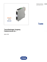
4.2 Device Design
Type 9186/12
# Device element Description
09134E00
15636E00
Screw terminals
1, 2 Terminal Not used
3, 4 Terminals 3 + 4 Fault message contact
21, 22 Terminals 5 + 6 Shield connection (equipotential bonding)
RS485 interface
5 Sub-D, RS485 RS485 interface, data line
Supply voltage status, RS485
6 Green LED Supply voltage indicator
7 Yellow LED Data transmission indicator
8 Green LED Data reception indicator
Port A status
9 Green LED LED for excellent receive level
10 Green LED LED for good receive level
11 Yellow LED System reserve reached
(fault message contact opened if both
green LEDs are off)
12 "ERR" LED, red Inadequate receive level,
fibre breakage at port A
13 Connection of
FO transmitter,
port A (left)
FO transmitter port A, TD-A
14 Connection of
FO receiver,
port A (left)
FO receiver port A, RD-A
Port B status
15 Green LED LED for excellent receive level
16 Green LED LED for good receive level
17 Yellow LED System reserve reached
(fault message contact opened if both
green LEDs are off)
18 "ERR" LED, red Inadequate receive level,
fibre breakage at port B
19 Connection of
FO transmitter,
port B (right)
FO transmitter port B, TD-B
20 Connection of
FO receiver,
port B (right)
FO receiver port B, RD-B
Connection terminals X4 for supply voltage (auxiliary power)
23 Terminal 2 0 V auxiliary power connection
24 Terminal 1 +24 V auxiliary power connection
6
7
8
12 3 4
9
10
11
12
15
16
17
18
19
20
5
13
14
21 22
23
24

Function and Device Design
10 918660330020
2023-10-20·HB00·III·en·02
DE
EN
FR
IT
ES
RU
NL
DK
SE
FI
PT
GR
PL
CZ
SK
HU
SL
RO
BG
LV
LT
EE
CH
KR
CN
Fibre optic isolating repeater
Series 9186
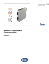
Type 9186/.5
# Device element Description
08625E00
Screw terminals
1 Terminal +24 V auxiliary power connection
2 Terminal 0 V auxiliary power connection
3, 4 Terminals 3 + 4 Fault message contact
RS485 interface
5 Sub-D, RS485 RS485 interface, data line
Supply voltage status, RS485
6 Green LED Supply voltage indicator
7 Yellow LED Data transmission indicator
8 Green LED Data reception indicator
Port A status
9 Green LED LED for excellent receive level
10 Green LED LED for good receive level
11 Yellow LED System reserve reached
(fault message contact opened if both
green LEDs are off)
12 "ERR" LED, red Inadequate receive level,
fibre breakage at port A
13 Connection of
FO transmitter,
port A (left)
FO transmitter port A, TD-A
14 Connection of
FO receiver,
port A (left)
FO receiver port A, RD-A
Port B status (only for type 9186/15-12-11)
15 Green LED LED for excellent receive level
16 Green LED LED for good receive level
17 Yellow LED System reserve reached
(fault message contact opened if both
green LEDs are off)
18 "ERR" LED, red Inadequate receive level,
fibre breakage at port B
19 Connection of
FO transmitter,
port B (right)
FO transmitter port B, TD-B
20 Connection of
FO receiver,
port B (right)
FO receiver port B, RD-B
6
7
8
12 3 4
9
10
11
12
15
16
17
18
19
20
5
13
14

918660330020
2023-10-20·HB00·III·en·02
Technical Data
11
DE
EN
FR
IT
ES
RU
NL
DK
SE
FI
PT
GR
PL
CZ
SK
HU
SL
RO
BG
LV
LT
EE
CH
KR
CN
Fibre optic isolating repeater
Series 9186
5 Technical Data
Marking
Type designation 9186/..-1.-11
CE marking 2
Explosion protection
Version 9186/12-11-11 9186/.5-12-11
Global (IECEx)
Gas and dust IECEx BVS 12.0081X IECEx BVS 13.0107X
Ex e mb ib [ia op is Ga] IIC T4 Gb Ex nA nC [op is T6 Ga] IIC T4 Gc
[Ex ia Da] IIIC [Ex op is Da] IIIC
Europe (ATEX)
Gas and dust BVS 06 ATEX E 145 X BVS 07 ATEX E 068 X
E II 2 (1) G Ex e mb ib [ia op is Ga]
IIC T4 Gb
E II 3 (1) G Ex nA nC [op is T6 Ga]
IIC T4 Gc
E II (1) D [Ex ia Da] IIIC E II (1) D [Ex op is Da] IIIC
Certifications and certificates
Certifications IECEx, ATEX, Brazil (INMETRO), Canada (cFM), USA (FM)
Ship certificates ABS, CCS, ClassNK, DNVGL, LR, RS
Further parameters
Installation In Zone 1 In Zone 2 and safe areas
Further information See relevant certificate and operating instructions
Safety data
Max. voltage Uo±3.7 V –
Max. current Io148 mA –
Max. power Po137 mW –
Safety-related maximum
voltage Um
253 V –
For RS485-IS
connection
Max. connectable
voltage Ui
±4.2 V –
Internal capacitance
Ci and inductance Li
negligible –
Ex i fault message
contact
Max. connectable
voltage Ui
24 V –
Max. connectable
current Ii
600 mA –
Internal capacitance
Ci and inductance Li
negligible –
Optical interface
Type of protection Ex op is IIC T6
Radiant power Po15 mW

Technical Data
12 918660330020
2023-10-20·HB00·III·en·02
DE
EN
FR
IT
ES
RU
NL
DK
SE
FI
PT
GR
PL
CZ
SK
HU
SL
RO
BG
LV
LT
EE
CH
KR
CN
Fibre optic isolating repeater
Series 9186
Technical data
Version 9186/12-11-11 9186/.5-12-11
Electrical data
Auxiliary power
Nominal voltage UN24 V DC
Voltage range 18 to 31.2 V
Residual ripple < 3.6 VSS
Nominal current
(at UN)
67 mA 130 mA
Power consumption ≤ 2 W 3 W
Operation indication Green "PWR" LED
Polarity reversal
protection
Yes
Galvanic separation
Test voltage
According to
standard
IEC/EN 60079-11 –
Between RS485
and auxiliary power
– 1.5 kV
Ex i RS485 to
auxiliary power
1.5 kV –
Fault message
contact to auxiliary
power
1.5 kV –
Equipotential
bonding to auxiliary
power
1.5 kV –
Ex i RS485 to fault
message contact
500 V –
Ex i RS485 to
equipotential
bonding
500 V –
Fault message
contact to
equipotential
bonding
500 V –
Optical interface
Protocols Protocol-transparent for RS485 interface
Network topologies Ring structure, linear structure, point-to-point connection
Redundancy Automatic changeover in the event of
a line fault
Automatic changeover in the event of
a line fault (except for 9186/25-12-11)
Connection ST®, BFOC/2.5 socket
Wavelength 850 nm
Transmission
distance
≤ 2000 m
Recommended
optical fibres
G 50/125 multi-mode
G 62.5/125 multi-mode
Integrated diagnostics function with alarm and automatic changeover to
reserve path. Therefore increased availability

918660330020
2023-10-20·HB00·III·en·02
Technical Data
13
DE
EN
FR
IT
ES
RU
NL
DK
SE
FI
PT
GR
PL
CZ
SK
HU
SL
RO
BG
LV
LT
EE
CH
KR
CN
Fibre optic isolating repeater
Series 9186
Electrical interfaces
Protocols PROFIBUS DP, Modbus, HART over RS485, R. STAHL ServiceBus (IS1+)
Version RS485-IS (PNO) RS485
Connection Sub-D socket X1, 9-pin
Transmission rate 1.2 kbps to 1.5 Mbps 9.6 kbps to 1.5 Mbps
Settings Fixed transmission rates can be set or automatic identification
(only for PROFIBUS DP)
Bit refresh Received bit is returned to its original form
Cable length Depends on transmission rate and cable according to PROFIBUS guideline
Transmission method 2-wire, half-duplex
End-of-line resistor To be connected in external connector
Data reception
indication
Green "RD" LED ON
Data transmission
indication
Yellow "TD" LED ON
Error control
Auxiliary power failure Fault message contact open
Good receive level Green and yellow "FO signal" LED, fault message contact closed
Reduced receive level
(-1.5 dBm)
Yellow "FO signal" LED, fault message contact open
Fibre breakage or
receive level too low
(-3 dBm)
Red "FO ERR" LED, fault message contact open
Switching capacity of
fault message contact
See Ex i values Max. 60 V DC, 42 V AC, 0.46 A
Electromagnetic
compatibility
Tested in accordance with the following standards and regulations:
IEC/EN 61326-1 For use in industrial areas
Ambient conditions
Ambient temperature -20 to +65 °C -20 to +60 °C
Installation conditions influence the ambient temperature.
Storage temperature -40 to +85 °C
Relative humidity
(no condensation)
≤ 95%
Use at the height of < 2000 m
Technical data
Version 9186/12-11-11 9186/.5-12-11

Technical Data
14 918660330020
2023-10-20·HB00·III·en·02
DE
EN
FR
IT
ES
RU
NL
DK
SE
FI
PT
GR
PL
CZ
SK
HU
SL
RO
BG
LV
LT
EE
CH
KR
CN
Fibre optic isolating repeater
Series 9186
Mechanical data
Connection technology
Auxiliary power Spring clamp terminal, 0.2 to 1.5 mm2
(Ex e)
Screw terminal, 0.2 to 2.5 mm2 Green
Fault message
contact
Screw terminal, 0.2 to 2.5 mm2 Blue
(Ex i)
Screw terminal, 0.2 to 2.5 mm2 Green
Shield connection to
equipotential bonding
Screw terminal, 0.2 to 2.5 mm2Blue Via DIN rail contact
Serial connection Sub-D socket X1, 9-pin
Shield Via Sub-D socket terminal strip
FO cable BFOC/2.5 for optical fibre 50/125, 62.5/125
Degree of protection
Enclosure IP30
Auxiliary power
terminals
IP20 IP30
Terminals IP30
Weight Approx. 330 g Approx. 200 g
Enclosure material PA 6.6
Fire resistance (UL-94) V0
Technical data
Version 9186/12-11-11 9186/.5-12-11

918660330020
2023-10-20·HB00·III·en·02
Technical Data
15
DE
EN
FR
IT
ES
RU
NL
DK
SE
FI
PT
GR
PL
CZ
SK
HU
SL
RO
BG
LV
LT
EE
CH
KR
CN
Fibre optic isolating repeater
Series 9186
For further technical data, see r-stahl.com.
Mounting/installation
Installation conditions
Mounting type On DIN rail (NS 35/15; NS 35/7.5)
Connection diagram 9186/12-..-..
05352E00
PIN RS485-IS
8 A-
3 B+
6 ISP+
5 ISGND
9186/15-..-..
05354E00
PIN RS485
8 A-
3 B+
6 U+
5 GND
9186/25-..-..
06005E00
PIN RS485
8 A-
3 B+
6 U+
5 GND
Technical data
Version 9186/12-11-11 9186/.5-12-11
5
6
x
x

Project Engineering
16 918660330020
2023-10-20·HB00·III·en·02
DE
EN
FR
IT
ES
RU
NL
DK
SE
FI
PT
GR
PL
CZ
SK
HU
SL
RO
BG
LV
LT
EE
CH
KR
CN
Fibre optic isolating repeater
Series 9186
6 Project Engineering
• Only connect the FO interface to compatible interfaces of Series 9186 devices.
NOTICE
An ambient temperature that is too high may cause failure of the devices installed
in the cabinet.
Non-compliance can result in material damage.
• Install and set up the cabinet in such a way that all devices installed within it
are always operated within their permissible temperature range.

918660330020
2023-10-20·HB00·III·en·02
Project Engineering
17
DE
EN
FR
IT
ES
RU
NL
DK
SE
FI
PT
GR
PL
CZ
SK
HU
SL
RO
BG
LV
LT
EE
CH
KR
CN
Fibre optic isolating repeater
Series 9186
6.1 PROFIBUS
Operation in a linear structure
Calculate the min. slot time Tslot_Init according to the following formula
Tslot_Init = a + b x L + 2 x N
where:
Tslot_Init: Min. slot time in bit times
N: Number of FO converters
L: Network reach in km
a, b: Length parameters (see table)
• Values a and b depend on the data rate and bus profile used (see table).
Adapt the slot time Tslot_Init accordingly in the system configuration.
• Ensure that the min. protocol processing time MIN TSDR is equal to at least 11 bit times
(MIN TSDR ≥ 11).
Table: Project engineering parameters for linear structures
The data transmission lines and network components may cause signal
delays. The bus parameters must therefore be adjusted using appropriate
project engineering software. The defined maximum network reach must also
be taken into account.
Data rate
[kBps]
a b
DP DP/FMS
1500 161 991 15
500 111 371 5
187.5 71 371 1.875
93.75 71 211 0.9375
45.45 411 411 0.4545
19.2 71 76 0.192
9.6 71 71 0.096

Project Engineering
18 918660330020
2023-10-20·HB00·III·en·02
DE
EN
FR
IT
ES
RU
NL
DK
SE
FI
PT
GR
PL
CZ
SK
HU
SL
RO
BG
LV
LT
EE
CH
KR
CN
Fibre optic isolating repeater
Series 9186
Operation in a redundant ring
A ring structure is made up of at least three type 9186 devices.
Calculate the min. slot time Tslot_Init according to the following formula
Tslot_Init = a + b x L + 44 x N
where:
Tslot_Init: Min. slot time in bit times
N: Number of FO converters
L: Network reach in km
a, b: Length parameters (see table)
• Values a and b depend on the data rate and bus profile used (see table).
Adapt the slot time Tslot_Init accordingly in the system configuration.
• Increase the RETRY LIMIT parameter by at least 3.
• Ensure that the min. protocol processing time MIN TSDR is equal to at least 11 bit times
(MIN TSDR ≥ 11). This is the case as standard.
Table: Project engineering parameters for ring structures
Example:
Number of FO converters in the ring: 4
Speed: 1.5 MBps
Total installed length of the FO: 4 km
Slot time to be set: Tslot_Init = a + b x L + 44 x N = 351 + 30 x 4 + 44 x 4 = 647 bit
Data rate
[kBps]
a b
DP DP/FMS
1500 351 2011 30
500 251 771 10
187.5 171 771 3.75
93.75 171 451 1.875
45.45 851 851 0.909
19.2 171 181 0.384
9.6 171 171 0.192
The slot time calculation only considers the optical network and the electrical
connection of bus devices over an RS485 bus segment up to a maximum
length of 20 m. Longer RS485 bus segments must also be accounted for by
adding them to the FO cable length.

918660330020
2023-10-20·HB00·III·en·02
Project Engineering
19
DE
EN
FR
IT
ES
RU
NL
DK
SE
FI
PT
GR
PL
CZ
SK
HU
SL
RO
BG
LV
LT
EE
CH
KR
CN
Fibre optic isolating repeater
Series 9186
6.2 Modbus/ServiceBus
Calculate the signal delay dT according to the following formula
dT= b x L + 2 x N
where:
Signal delay in bit times for a complete signal cycle
b: Length parameter (table)
L: Network reach in km
N: Number of fibre optic isolating repeaters
For the FO ring to function correctly, dT must be smaller than the shortest frame in bits.
Table: Correlation of data rate and length parameter b
Data transmission lines and network components may cause signal delays.
If necessary, these must be taken into account when configuring the
TIMEOUT times of the bus system used.
Data rate b
1.5 MBps 15
500 kBps 5.00
375 kBps 3.75
187.5 kBps 1.88
93.75 kBps 0.94
57.6 kBps 0.58
38.4 kBps 0.38
19.2 kBps 0.19
9.6 kBps 0.10
4.8 kBps 0.048
2.4 kBps 0.024
1.2 kBps 0.012

Project Engineering
20 918660330020
2023-10-20·HB00·III·en·02
DE
EN
FR
IT
ES
RU
NL
DK
SE
FI
PT
GR
PL
CZ
SK
HU
SL
RO
BG
LV
LT
EE
CH
KR
CN
Fibre optic isolating repeater
Series 9186
Modbus
For Modbus and similar UART protocols: At a minimum frame length of 44 bits,
the maximum FO ring size is determined based on the number of devices and the
transmission rate.
Table: FO ring size in Modbus operating mode (various data rates)
Number
of
devices
Data rate [kBps] of the FO ring size [km]
1.2 2.4 4.8 9.6 19.2 38.4 57.6 93.75 187.5 500 1500
2 Not permissible
3 9.90 9.90 9.90 9.90 9.90 9.90 9.90 9.90 9.90 9.90 5.53
4 13.20 13.20 13.20 13.20 13.20 13.20 13.20 13.20 13.20 13.20 5.41
6 19.80 19.80 19.80 19.80 19.80 19.80 19.80 19.80 19.80 15.56 5.19
8 26.40 26.40 26.40 26.40 26.40 26.40 26.40 26.40 26.40 14.88 4.96
10 33.00 33.00 33.00 33.00 33.00 33.00 33.00 33.00 33.00 14.20 4.73
12 39.60 39.60 39.60 39.60 39.60 39.60 39.60 39.60 39.05 13.52 4.51
14 46.20 46.20 46.20 46.20 46.20 46.20 46.20 46.20 34.24 12.84 4.28
16 52.80 52.80 52.80 52.80 52.80 52.80 52.80 52.80 32.43 12.16 4.05
18 59.40 59.40 59.40 59.40 59.40 59.40 59.40 59.40 30.61 11.48 3.83
20 66.00 66.00 66.00 66.00 66.00 66.00 66.00 57.60 28.80 10.80 3.60
22 72.60 72.60 72.60 72.60 72.60 72.60 72.60 53.97 26.99 10.12 3.37
24 79.20 79.20 79.20 79.20 79.20 79.20 79.20 50.35 25.17 9.44 3.15
26 85.80 85.80 85.80 85.80 85.80 85.80 76.04 46.72 23.36 8.76 2.92
28 92.40 92.40 92.40 92.40 92.40 92.40 70.14 43.09 21.55 8.08 2.69
30 99.00 99.00 99.00 99.00 99.00 96.35 64.24 39.47 19.73 7.40 2.47
32 105.60 105.60 105.60 105.60 105.60 87.50 58.33 35.84 17.92 6.72 2.24
/