Page is loading ...

Trademark Acknowledgements
Prima, PrimaConnex, PrimaSolo, RENOVA, RESTORE, STAGE-1, DynaBlast, DynaGraft•D, DynaMatrix, CALMATRIX,CALFORMA,TEFGEN-FD, TEFGEN-PLUS,TEFGEN and
TiLobe are trademarks of Keystone Dental, Inc.
Manufacturer
Keystone Dental, Inc.
144 Middlesex Turnpike
Burlington, MA 01803 USA
Call: 1-866-902-9272
Fax: 1-866-903-9272
Outside the USA
Call: +1-781-328-3490
Fax: +1-781-328-3400
Authorized Representative
Keystone Dental SpA
via A. Fleming, 19
37135 Verona, Italy
Call: +39-045-8230294
Fax: +39-045-8250296
Subsidiary:
Keystone Dental AB
Särö, Sweden
Call: +46-31-93-68-23
Fax: +46-31-93-68-45
Subsidiary:
Keystone Dental GmbH
Alfter, Germany
Call: +49-2222-9294-0
Fax: +49-2222-977356
Subsidiary:
Keystone Dental S.A.S.
Beauzelle, France
Call: +33-5-62-21-40-45
Fax: +33-5-61-42-06-32
Email: [email protected]
www.keystonedental.com
0123
only
The products described herein are covered by one or more of the following patents:
US 5,996,779, US 6,142,296, US 7,249,949, and applicable international patents.
Additional patents are pending.
© Keystone Dental, Inc. 2010 MK40041 Rev. B 07/2010
RESTORE
®
Implant System
Prosthetic Manual

Introduction
This Prosthetic Manual is designed to aid clinicians in basic prosthetic procedures using the RESTORE External
Hex Implant System. The abutment systems described can be used in all areas of the mouth, for single tooth
applications, fixed or detachable bridgework and overdenture techniques.
The procedures and guidelines presented in this Manual are not a substitute for formal implant restoration
training for the restoring doctor and dental laboratories. It is the responsibility of the clinicians and dental
laboratories to determine the final protocol and component selection.
Pre-Prosthetic Considerations 2-3
Introduction 2
Indications 2
Sterilization 2
Basic Prosthetic Case Design Principles 3
Prosthetic Tables 4
Accu-Torque Wrenches and Drivers 5
Impression Taking Guidelines 6-10
Procedure for Taking an Open Tray Impression 7-8
Procedure for Taking a Closed Tray Impression 9-10
Cement-Retained Restorations 11-19
Cement-on Crown (COC) Abutment System
Lab Preparation of the COC Abutment
Impressioning 11
Master Model Fabrication 12
COC Abutment Modification 12
Metal Framework Fabrication 12
Metal Framework Try-in 13-14
Porcelain Application 14
Final Insertion 14
Chairside Preparation and Temporization
Chairside Preparation 15-16
Fabrication of the Restoration 16
Final Insertion 16
Custom Abutment Fabrication with the UCLA Abutment
Master Model and Abutment Fabrication 17-18
Final Insertion 18-19
Screw-Retained Restorations 20-23
UCLA Abutment System
Impressioning 20
Master Model Fabrication 21
Abutment Selection 21
Metal Framework Fabrication 21-22
Metal Framework Try-in 22
Porcelain Application 22-23
Final Insertion 23
Overdenture Restorations 24-31
Restorative Options 24
Preliminary Considerations 25
Snap Abutment System
Technical Considerations 25
O-Ring Abutment System
Technical Considerations 26
Laboratory Fabrication of a New Denture
Impressioning 26
Master Model Fabrication 27
Abutment Selection and
Finishing the Final Prosthesis 27-28
Delivering the Final Prosthesis 28-29
Alternative Procedure
Doctor Placement of Snap or O-Ring Abutments 30
Master Model Fabrication 31
Delivering the Final Prosthesis 31
Bar Attachment-Retained Overdentures 32-39
UCLA Abutment System
Technical Considerations 33
Impressioning 33
Master Model Fabrication 33
Wax Rim Fabrication 33
Verification Jig Fabrication 34-35
Interocclusal Record 35
Denture Wax Set-up and Model Verification 36
Denture Wax Try-in for the Patient 36
Bar Fabrication 36-37
Framework Try-in 38
Sectioning Framework Procedure 38-39
Processing 39
Final Insertion 39
Fixed Detachable Restorations 40-48
Fixed Detachable Abutment System
Technical Considerations 40
Abutment Placement and Impressioning 40-41
Master Model Fabrication 41
Wax Rim Fabrication 41-42
Verification Jig Fabrication 42
Interocclusal Record 42-43
Denture Wax Try-in and Model Fabrication 43
Denture Wax Try-in for the Patient 43
Framework Fabrication 43
Optional Method for a Matrix 44-45
Framework Try-in 45-46
Sectioning Framework Procedure 46
Denture Wax Set-up and Model Verification 46-47
Denture Wax Try-in for Patient 47
Processing 47
Final Insertion 48
Indications
The RESTORE Implant System is intended for use in either partially or fully edentulous areas in the maxilla or
mandible in support of single or multi-unit restorations. The implants also function as terminal or intermediate
abutment support for fixed bridgework.
PROSTHETIC CONSIDERATIONS:
• Cement-Retained Restorations (Fixed) utilizing multiple abutments
• Screw-Retained Restorations (Fixed Removable) utilizing multiple abutments
• Implant or Bar Attachment-Retained Overdenture Restorations
• Single Tooth Restorations without involvement of adjacent dentition
Federal (USA) law restricts this device to sale by or on the order of a licensed dentist or physician.
2
www.keystonedental.com
pre-prosthetic considerations
Sterilization
Select prosthetic components are provided in sterile, gamma irradiated packaging. Please refer to
individual package labeling to determine if the prosthetic component is sterile.
If necessary, all-metal components can be re-sterilized according to Keystone Dental’s
sterilization table:
Sterilization Table
1. Autoclave: 121-124ºC (~250ºF) 60 minute exposure / 40 minute dry time or 132-135ºC (~270ºF) 40 minute
exposure / 30 minute dry time. Do not exceed 140˚C (~284˚F). Always use the dry cycle.
2. Dry Heat: 160˚C (320˚F) 120 minutes (minimum). Do not exceed 170˚C (338˚F).
It is recommended that the proper biological indicators for the selected sterilization method accompany each load
and that the appropriate sterile packaging be used to maintain sterility until use.
Keystone Dental does not recommend chemclave sterilization procedures as they may damage surgical
trays and/or instruments.
Do not use the original packaging in the autoclave! Autoclave re-sterilization can only be accomplished by
placing the individual components in the surgical tray, a sealed autoclave bag or in a surgical towel.
Symbols Key
= Note = Tip= Caution
table of contents
Keystone Dental, Inc. 866-902-9272 (U.S.A.) 1-781-328-3490 (International)

Basic Prosthetic Case
Design Principles
Evaluate the following parameters when choosing the
number of implants for the type of restoration used:
PROPER PROSTHETIC LOADING:
To ensure proper prosthetic loading, it is necessary to
distribute the loads over the greatest bone-to-implant
surface area possible. To do so, place the largest
implant body available that the bone will
accommodate. Long cantilevers and large
inter-implant spaces should be avoided.
PARTIALLY EDENTULOUS ARCH:
For the partially edentulous arch, total implant support
of the restoration without involving natural teeth, is
recommended when possible.
FULLY EDENTULOUS ARCH:
For a maxillary implant-supported, fixed detachable
restoration or bar attachment-retained overdenture,
implants are usually placed from the bicuspid area in
one quadrant of the maxillary arch to the bicuspid
area on the opposite quadrant of the arch to avoid the
maxillary sinuses. A fixed detachable restoration
usually requires five to six implants, while a bar
attachment-retained bar overdenture usually requires
four to six implants. Place the implants as
symmetrically as possible to ensure balanced occlusal
forces. For a mandibular implant-supported, fixed
detachable or bar attachment-retained overdenture,
implants are usually placed in the symphysis between
the mental foramen or distal to the mental foramen,
avoiding the anatomical restrictions of the
mandibular canal.
For an implant attachment-retained overdenture, two
to three implants are usually sufficient. Overdenture
abutments should not be used if implants are
divergent beyond 15 degrees.
pre-prosthetic considerations
3
Keystone Dental, Inc. 866-902-9272 (U.S.A.) 1-781-328-3490 (International)
4
www.keystonedental.com
prosthetic tables
Keystone Dental’s external hex dental implants are engineered around three (3) prosthetic table diameters for clinical versatility,
stability and strength. “Prosthetic Table” refers to the outside diameter at the top of the implant where the prosthetic compo-
nent interfaces with the implant. The Restore prosthetic tables are divided into Small Diameter (SD), Regular Diameter (RD) and
Wide Diameter (WD). Each diameter is described below.
1 Klardie, M. “Small Diameter (SD) Implants: A Strength Comparison.” Oral Restorative Update
Vol. 4, No. 2 (1997).
2 Binon, P. “Evaluation of Three Slip Fit Hexagonal Implants.” Implant Dentistry 5.4 (1996).
3 Binon, P. “Test Data Confirms Close Tolerance Machining of Restore
®
System.”
Oral Restorative Update Vol. 3, No. 1 (1996).
4 Slabberkoom, Scott D., P.E., M.S.E., “Wide Diameter Implants - A Balanced Design Approach.”
Oral Restorative Update, Fall 1996.
Small Diameter
Surgical and Restorative Flexibility
• Used on RESTORE 3.3mm implants.
• The SD implant’s narrow prosthetic table makes it an
excellent choice when interproximal space is limited.
• The SD’s 1mm tall external hex provides greater support
and tactile feel when seating components, allowing a more
positive seat.
• The SD is ideal for single tooth restorations due to its
increased strength.
1
Wide Diameter
Leader of the Wides
• Used on RESTORE 5.0 and 6.0mm implants.
• Solid design maximizes overall performance when
interacting with compressive occlusal forces, off-axis
occlusal forces and torsional forces.
• Provides 79% more surface area and 43% more height
4
than the standard hex size for unparalleled strength and
exceptional resistance to deformation and stripping of
the hex.
4
• 2.5mm abutment screw provides 65% more strength than
the standard 2.0mm screw for additional resistance to
off-axis loads and improved torque retention.
4
Regular Diameter
Universal Compatibility
• Used on RESTORE 3.75 and 4.0mm implants.
• Design based on 30+ years of clinical research.
• A leader in prosthetic connection fit.
2-3
• RD implants provide universal prosthetic
compatibility with the following implant systems:
• Nobel Biocare
®
- 3.75, 4.0mm
• Steri-Oss HL - 3.8, 4.5mm
• Zimmer Taper-Lock
®
- 3.75mm
• Implant Innovations, 3i - 3.75, 4.0mm
2.4mm
3.3mm Table
1.0mm
2.7mm
4.1mm Table
0.7mm
1.0mm
3.3mm
5.0mm Table

ACCU-TORQUE WRENCHES
Accu-Torque Wrenches are available in three torque calibrations. Refer to the table
below for torque recommendations.
ACCU-TORQUE DRIVERS
Keystone Dental offers Accu-Torque Drivers in several hex sizes and lengths.
See the RESTORE Product Catalog for all available sizes and lengths.
Accu-Torque Wrenches
Accu-Torque Drivers
TORQUE GUIDELINES
•
Place the driver into the abutment or fastening screw. Be sure that the
hex hole is fully engaged with the driver.
•
With the rounded edge facing downward, seat the torque wrench driver
into the wrench.
•
Place a finger on the head of the torque wrench. Follow the direction of
the arrow and tighten to the specific torque value stated below.
•
When the head of the torque wrench “breaks” or releases, do not tighten
any further or the abutment/fastening screw may strip or break.
TORQUE RECOMMENDATIONS
ABUTMENT SCREWS
1
(GOLD OR TITANIUM)
30Ncm
FASTENING SCREWS
2
(GOLD OR TITANIUM)
10Ncm
ABUTMENT SCREWS
1
(GOLD OR TITANIUM)
30Ncm
FASTENING SCREWS
2
(GOLD OR TITANIUM)
10Ncm
ABUTMENT SCREWS
1
(GOLD OR TITANIUM)
30Ncm
FASTENING SCREWS
2
(TITANIUM)
20Ncm
1. Abutment screws engage the internal threads of the implant.
2. Fastening screws engage the internal threads of a transmucosal abutment (i.e. standard or conical abutments).
Small Diameter (SD)
3.3mm and 3.4mm Implants
Wide Diameter (WD)
5.0mm and 6.0mm Implants
Regular Diameter (RD)
3.75mm, 4.0mm and 4.2mm Implants
accu-torque wrenches and drivers
UCLA IMPRESSION POSTS
Use the appropriate diameter of the UCLA Impression Post to match
the contour of the healing abutment. For more details on contoured
healing abutments, see the RESTORE Product Catalog.
FEATURES:
When seating the impression post onto the implant, the impression post
captures the implant’s vertical and the rotational position of the hex. The
engagement of the male hex portion of the implant and the female portion of
the impression post provides the “anti-rotation” of the abutment on the implant.
These UCLA Impression Posts all have a female hex at the base of the
impression post body.
PROCEDURE FOR SEATING THE UCLA IMPRESSION POST
:
Place the long screw (Open Tray Technique) or short screw (Closed Tray Technique)
into the top of the impression post body. Use the .048" Hex Driver to seat the
impression post onto the hex of implant. Turn the screw two or three times to
engage the implant threads. Rotate the impression post body until it drops over
the hex of the implant. Turn the screw firmly until it is completely tightened. Take
an x-ray to verify that the impression post is completely seated.
If bone or soft tissue prevents the impression post from fully seating on the
implant, use the Bone Profiler to clean up the interface. This will help to
create proper bone contours. For more details on the Bone Profiler System
see the RESTORE Product Catalog.
UCLA Impression Post
with Long & Short Screw
IMPLANT LEVEL IMPRESSION POSTS
The majority of impressions taken are implant level impressions. Each diameter impression post is packaged with a
long screw for an open tray impression or a short screw for a closed tray impression. When implants are divergent
from each other, angled or placed across the arch, an open tray impression is recommended. When restoring a
single tooth implant, a closed tray impression can be used.
impression taking guidelines
5.0mm
RD Profilers for 3.75mm, 4.0mm & 4.2mm
External Hex Implants
6.0mm 7.5mm
Guide
Pin
5.0mm 6.0mm 7.5mm
Healing Abutments
5.0mm 6.0mm 7.5mm
5
Keystone Dental, Inc. 866-902-9272 (U.S.A.) 1-781-328-3490 (International)
6
www.keystonedental.com

Step 1: Take an alginate impression of the implant site and fabricate a full arch
custom tray.
(Block out over the implant sites approximately 15mm. All other areas of the
arch use the standard block out technique.)
Step 2: Cut hole(s) in the top of the custom tray over the implant sites to allow the
Impression Post Screw to protrude through the top of the tray.
Step 3: Remove the healing abutment with a .048” Hex Driver.
(If it is a multi-unit restoration, remove one healing abutment at a time and
then place an impression post to prevent the tissue from slumping.)
Step 4: Inspect the implant prosthetic table for tissue invagination.
(If tissue is covering the prosthetic table, replace the healing abutment lightly
and return to the surgeon or contact the surgeon for guidance.)
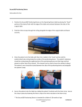
Step 5: Place the open tray transfer impression post on the implant prosthetic table
with the same hex driver. (Slide the screw down through the top of the
impression post body. Seat the screw and impression post together on the
prosthetic table. Tighten the screw with one turn clockwise to engage the
threads. Then, seat the body of the post over the hex of the implant. Tighten the
screw using firm finger pressure.)
Step 6: Use an x-ray to verify that the impression post is
completely seated. (The x-ray cone should be
perpendicular to the implant prosthetic table.)
Step 7: Place the custom tray in the mouth to verify that
the screws are extended approximately 2mm above
the top of the tray.
Step 8: Block out the hex hole in the top of the screw.
(Use wax, Cavit
®
, Gutta Percha or Play-Doh
®
.)
Step 9: Syringe the impression material around the entire body of the impression
post exposing only the top of the screw.
(Impression materials can be any medium to heavy body polyvinylsiloxane.)
Step 10: Fill and seat the custom tray in the mouth covering the impression post and
exposing the top of the screw through the hole in the top of the tray.
Step 11: Once the impression tray is seated, remove
some of the impression material from the top
of the tray to expose the screw through the top
of the tray.
Step 12: Once the material has set, remove the screw
from the impression and remove the impression
tray from the mouth.
(The impression post will be embedded inside of
the impression.)
Step 13: Replace the healing abutment.
(Remove one impression post at a time and seat the healing abutment.)
Step 14: Inspect the impression for accuracy.
Step 16: Send the impression with the seated impression post, opposing model and
bite to the laboratory.
Step 15: Place the implant analog (replica of the implant)
into the hex of the impression post body. Slide
the screw through the top of the impression and
engage the analog. (Hand tighten the screw.
Firmly hold the analog so the impression post
will not move or dislodge.)
7
Keystone Dental, Inc. 866-902-9272 (U.S.A.) 1-781-328-3490 (International)
8
www.keystonedental.com
procedure for taking an open tray impression
procedure for taking an open tray impression

Step 1: Take an alginate impression of the implant site and fabricate a full arch
custom tray.
(Block out over the implant sites approximately 15mm. All other areas of the
arch use the standard block out technique.)
Step 2: Cut hole(s) in the top of the custom tray over the implant sites to allow the
Impression Post Screw to protrude through the top of the tray.
Step 3: Remove the healing abutment with a .048” Hex Driver.
(If it is a multi-unit restoration, remove one healing abutment at a time and
then place an impression post to prevent the tissue from slumping.)
Step 4: Inspect the implant prosthetic table for tissue invagination.
(If tissue is covering the prosthetic table, replace the healing abutment lightly
and return to the surgeon or contact the surgeon for guidance.)
Step 5: Place the open tray transfer impression post on the implant prosthetic table
with the same hex driver. (Slide the screw down through the top of the
impression post body. Seat the screw and impression post together on the
prosthetic table. Tighten the screw with one turn clockwise to engage the
threads. Then, seat the body of the post over the hex of the implant. Tighten the
screw using firm finger pressure.)
Step 6: Use an x-ray to verify that the impression post is
completely seated. (The x-ray cone should be
perpendicular to the implant prosthetic table.)
Step 7: Place the custom tray in the mouth to verify that
the screws are extended approximately 2mm above
the top of the tray.
Step 8: Block out the hex hole in the top of the screw.
(Use wax, Cavit
®
, Gutta Percha or Play-Doh
®
.)
Step 9: Syringe the impression material around the entire body of the impression
post exposing only the top of the screw.
(Impression materials can be any medium to heavy body polyvinylsiloxane.)
Step 10: Fill and seat the custom tray in the mouth covering the impression post and
exposing the top of the screw through the hole in the top of the tray.
Step 11: Once the impression tray is seated, remove
some of the impression material from the top
of the tray to expose the screw through the top
of the tray.
Step 12: Once the material has set, remove the screw
from the impression and remove the impression
tray from the mouth.
(The impression post will be embedded inside of
the impression.)
Step 13: Replace the healing abutment.
(Remove one impression post at a time and seat the healing abutment.)
Step 14: Inspect the impression for accuracy.
Step 16: Send the impression with the seated impression post, opposing model and
bite to the laboratory.
Step 15: Place the implant analog (replica of the implant)
into the hex of the impression post body. Slide
the screw through the top of the impression and
engage the analog. (Hand tighten the screw.
Firmly hold the analog so the impression post
will not move or dislodge.)
7
Keystone Dental, Inc. 866-902-9272 (U.S.A.) 1-781-328-3490 (International)
8
www.keystonedental.com
procedure for taking an open tray impression
procedure for taking an open tray impression

Step 6: Block out the hex hole in the top of the screw.
(Use wax, Cavit, Gutta Percha or Play-Doh.)
Step 5: Use an x-ray to verify that the impression post
is completely seated. (The x-ray cone should be
perpendicular to the implant prosthetic table.)
Step 4: Place the closed tray transfer impression post on
the implant prosthetic table with the same
hex driver.
(Slide the screw down through the top of the
impression post body. Then, seat the screw and
impression post together on the prosthetic table.
Tighten the screw one turn clockwise to engage
the threads. Then, seat the body of the post over
the hex of the implant. Tighten the screw using
firm finger pressure.)
Step 1: Take an alginate impression of the implant site and fabricate a full arch
custom tray. (Block out over the implant sites approximately 15mm. All the
other areas of the arch use a standard block out technique.)
Step 2: Remove the healing abutment with a .048” Hex Driver.
(If it is a multi-unit restoration, remove one healing abutment at a time and
place the impression post to avoid the tissue from slumping.)
Step 3: Inspect the implant prosthetic table for tissue invagination. (If the tissue is
covering the prosthetic table, replace the healing abutment lightly and return
to the surgeon or contact the surgeon for guidance.)
Step 7: Syringe the impression material around the entire impression post.
(Impression materials can be any medium to heavy body polyvinylsiloxane.)
Step 8: Fill the full arch impression tray with impression material and seat the
custom tray in the mouth covering the impression post.
Step 9: Once the material has set in the mouth, remove the impression tray.
(The impression post body and short screw will remain in the mouth.)
Step 10: Remove the impression post with the same hex
driver and replace the healing abutment.
Step 11: Inspect the impression for accuracy.
Step 12: Take the impression post and analog (replica of the implant), seat the
impression post onto the analog and hand tighten the screw with a
hex driver.
Step 13: Seat the impression post back into the
impression with the flat side
of the post
to the flat side of the impression.
Step 14: Send the impression with the seated impression post, opposing model and
bite to the laboratory.
9
Keystone Dental, Inc. 866-902-9272 (U.S.A.) 1-781-328-3490 (International)
10
www.keystonedental.com
procedure for taking a closed tray impression
procedure for taking a closed tray impression

Step 6: Block out the hex hole in the top of the screw.
(Use wax, Cavit, Gutta Percha or Play-Doh.)
Step 5: Use an x-ray to verify that the impression post
is completely seated. (The x-ray cone should be
perpendicular to the implant prosthetic table.)
Step 4: Place the closed tray transfer impression post on
the implant prosthetic table with the same
hex driver.
(Slide the screw down through the top of the
impression post body. Then, seat the screw and
impression post together on the prosthetic table.
Tighten the screw one turn clockwise to engage
the threads. Then, seat the body of the post over
the hex of the implant. Tighten the screw using
firm finger pressure.)
Step 1: Take an alginate impression of the implant site and fabricate a full arch
custom tray. (Block out over the implant sites approximately 15mm. All the
other areas of the arch use a standard block out technique.)
Step 2: Remove the healing abutment with a .048” Hex Driver.
(If it is a multi-unit restoration, remove one healing abutment at a time and
place the impression post to avoid the tissue from slumping.)
Step 3: Inspect the implant prosthetic table for tissue invagination. (If the tissue is
covering the prosthetic table, replace the healing abutment lightly and return
to the surgeon or contact the surgeon for guidance.)
Step 7: Syringe the impression material around the entire impression post.
(Impression materials can be any medium to heavy body polyvinylsiloxane.)
Step 8: Fill the full arch impression tray with impression material and seat the
custom tray in the mouth covering the impression post.
Step 9: Once the material has set in the mouth, remove the impression tray.
(The impression post body and short screw will remain in the mouth.)
Step 10: Remove the impression post with the same hex
driver and replace the healing abutment.
Step 11: Inspect the impression for accuracy.
Step 12: Take the impression post and analog (replica of the implant), seat the
impression post onto the analog and hand tighten the screw with a
hex driver.
Step 13: Seat the impression post back into the
impression with the flat side
of the post
to the flat side
of the impression.
Step 14: Send the impression with the seated impression post, opposing model and
bite to the laboratory.
9
Keystone Dental, Inc. 866-902-9272 (U.S.A.) 1-781-328-3490 (International)
10
www.keystonedental.com
procedure for taking a closed tray impression
procedure for taking a closed tray impression

Cement-on Crown (COC) Abutment System
The COC Abutment is a titanium tapered abutment that extends through the tissue into the oral cavity. It contains
an internal hex to aid in anti-rotation when used as a single tooth abutment. The abutment is held in place on the
implant using a separate gold or titanium screw. The COC Abutments are available in the Small Diameter (SD),
Regular Diameter (RD) and Wide Diameter (WD) prosthetic tables with straight, 15
°
Angle or 25
°
Angle
and with 2mm or 4mm cuff height.
PROSTHETIC OPTIONS:
•
Can be used for single or multi-unit (splinted) crown and bridge restorations.
•
The gold screw requires the use of a Square Driver. The titanium screw requires a .048" Hex Driver.
•
Pre-machined margins simplify abutment preparation. In addition, they may be prepared to follow
gingival contours.
TECHNICAL CONSIDERATIONS
:
•
A minimum interocclusal clearance of 4.5mm plus the restoration thickness is required between the implant
prosthetic table and the occlusal plane.
•
The straight locking COC Abutment may be used when space near the adjacent teeth or implants
is limited.
TWO METHODS FOR PREPARATION OF THE COC ABUTMENT
:
1. If the patient has a temporary prosthesis that they are currently wearing, then you may elect to have the
laboratory prepare the COC Abutment. See the following section on Lab Preparation of the COC Abutment.
2. If the patient requests that they leave the office with a temporary restoration, then the COC Abutment must
be prepared chairside and a temporary restoration must be fabricated. See the Chairside Preparation and
Temporization section on pages 15 and 16 of this Prosthetic Manual.
LAB PREPARATION OF THE COC ABUTMENT
CLINICAL PROCEDURE
Impressioning
When abutment(s) are prepared in the dental laboratory, an implant level impression utilizing either a
closed tray or open tray technique is required. Refer to pages 6-10 of this Prosthetic Manual for implant level
impression techniques.
Straight COC Abutments
15° 25°
LABORATORY PROCEDURE
Master Model Fabrication
Attach the implant analogs to the impression posts. A soft tissue model is
recommended to provide an accurate replication of the patient’s soft tissue.
Step 1: Pour the soft tissue around the implant analogs. When the material has
set, pour a stone master model.
COC Abutment Modification
Step 2: When selecting the proper COC Abutment cuff height, measure the tissue
depth from the top of the implant analog to the height of the soft tissue.
For esthetics, the final margin of the COC Abutment should be 1-2mm
below the tissue height.
Step 3: Place the COC Abutment. Determine if a reduction in the height of the
abutment and/or the cuff is required. Mark the abutment with a felt
tip marker.
Step 4: Modify the COC Abutment.
To improve stability while adjusting the COC Abutment, attach an implant
analog to the abutment.
For multi-unit cases, the laboratory may fabricate a “positioning jig” using
a pattern resin material. The clinician can transfer the abutment from the
master model to the mouth, simplifying the abutment seating procedure.
Step 5: After preparation is complete, block out the top of the screw access hole to
prevent wax from flowing into this area.
Metal Framework Fabrication
Step 6: Wax the understructure using conventional crown and bridge techniques.
When waxing the understructure, using a die spacer is recommended. Keep
in mind that the actual size of the final crown will be smaller buccal/lingual
than the normal tooth or teeth the restoration is replacing.
Step 7: Spruing, investing and casting is completed following conventional crown
and bridge techniques.
Step 8: Finish the metal framework using conventional crown and bridge
techniques.
To confirm a passive fit of multi-unit restorations, an inter-oral metal try-in
is recommended.
Height Reduction Marked
Completed COC Abutments
Waxed Understructure Sprued
Master Model
2mm
4mm
Wax Understructure Completed
Completed Positioning Jig
11
Keystone Dental, Inc. 866-902-9272 (U.S.A.) 1-781-328-3490 (International)
cement-retained restorations
12
www.keystonedental.com
4mm
4mm
2mm
2mm
Locking
Non-Locking
Angled COC Abutments

CLINICAL PROCEDURE
Metal Framework Try-In
Step 1: Remove the healing abutment(s) using a .048" Hex Driver.
Remove one healing abutment at a time and place the appropriate COC
Abutment (to prevent tissue slumping). When removing the healing abut-
ments, working from the posterior of the patient’s mouth to the
anterior is recommended. If the laboratory fabricated a positioning jig,
remove all of the healing abutments and seat the abutment(s) utilizing the
positioning jig.
Gold abutment screws require the use of a square driver. Titanium
abutment screws require a .048" Hex Driver.
Step 2: Remove the metal framework from the master model. Before placement in
the mouth, note on the model the orientation marks on the COC
Abutments.
Step 3: Place the COC Abutments in the patient’s mouth. Note the position the
orientation dots/marks as they were on the model or use a positioning jig
if supplied.
Step 4: Take an x-ray to verify that the abutment(s) are completely seated.
Step 5: Use a 30Ncm Accu-Torque Wrench and an Accu-Torque Driver to tighten
the abutment(s) in the mouth.
Step 6: Place the metal framework and verify that the framework fits passively.
13
Keystone Dental, Inc. 866-902-9272 (U.S.A.) 1-781-328-3490 (International)
14
www.keystonedental.com
COC Abutments on Model
COC Abutments in Mouth
Metal Framework Seated
Applying Torque
(Normal wrench
position)
Torque Applied
(Wrench head in
broken/release
position)
If the framework binds as it is seated or does not go completely down to
the margin of the abutment(s), then the bridge must be cut, related in the
mouth and returned to the laboratory for soldering/laser welding. It may
be possible to use an indicating spray or paste to determine if the internal
aspect of the bridge can be modified to allow the bridge to seat.
If the framework is not passive, mark the area where the abutment is not
seating and needs to be sectioned. Then, remove the framework from the
patient’s mouth. Section the framework, creating a space of approximately
0.3mm using an ultra-thin disc. Using a pattern resin material, lute the sec-
tions of the framework together.
Once the material has set to the manufacturer’s specifications:
• Return the metal framework to the laboratory to be soldered/laser
welded and returned for an (optional) secondary framework try-in.
OR
• Pick up the luted together framework in a secondary full arch impression.
Then, return the framework to the laboratory for soldering/laser welding
and porcelain application.
Step 7: Block out the screw access hole(s) with a retrievable material and cement
the temporary prosthesis.
LABORATORY PROCEDURE
Porcelain Application
Proceed with porcelain application following normal laboratory procedures. Return
the restoration on the master model to the clinician.
CLINICAL PROCEDURE
Final Insertion
Remove the temporary prosthesis from the patient’s mouth. Verify that the
temporary cement is completely removed from the abutment. Place the final
restoration onto the abutments prior to cementation. Check the occlusion, contacts
and margin integrity. There should be no occlusal contact in excursive movements
and only light contact in centric occlusion. Once satisfied, use temporary cement
for easier retrievability if future access to the abutment/screw is desired.
Block Out of Screw Access Holes
Final Restoration
cement-retained restorations
Completed Positioning Jig

CLINICAL PROCEDURE
Chairside Preparation
Preparation of Straight or Angled COC Abutments follows a similar
process. Slight changes in preparation of the Angled COC Abutments will be
noted in this section.
When intraoral abutment modification is necessary, use copious amounts of
irrigation to eliminate excessive heat buildup in the surrounding bone tissue
that may compromise the osseointegration of the implant.
Step 1: Remove the healing abutment using a .048" Hex Driver.
Step 2: When selecting the proper COC Abutment cuff height, measure the tissue
depth from the top of the implant to the height of the soft tissue. For
esthetics, the margin of the abutment (the cuff height) should be 1-2mm
below the gingival tissue height.
Step 3: Use your hex driver to seat the appropriate COC Abutment (Straight or
Angled). Determine if a reduction in the height of the abutment and/or the
cuff is required. Mark the abutment with a carbide bur or felt tip marker.
A twelve-point locking mechanism on the base of the Angled COC
Abutment permits the correct indexing of the abutment for proper angle
correction.
Step 4: Remove the abutment from the patient’s mouth and modify the abutment.
To improve abutment stability while adjusting, attach an implant analog to
the abutment.
Step 5: After the correct height is obtained, place the COC Abutment, then use an
x-ray to verify a complete seating. Tighten the abutment screw using a
30Ncm Accu-Torque Wrench and a .048” or Square Accu-Torque Driver.
Step 6: Final adjustments using a coarse diamond bur may be completed in
the mouth.
15
Keystone Dental, Inc. 866-902-9272 (U.S.A.) 1-781-328-3490 (International)
16
www.keystonedental.com
Marking Height Reduction
Height Reduction
In Mouth Preparation
COC Abutments Ready for Impression
After final preparations are made, verify that the abutment has not come
loose. Do so by tightening the abutment screw with the torque wrench.
Step 7: Protect the abutment screw from cement by filling in the screw access
hole(s) with a Cavit, Gutta Percha or a material such as Fermit
®
, which is a
light-cured, very firm material that can be easily removed if necessary.
Step 8: Conventional impression techniques are used for the final restoration.
(Always take a full arch impression.) If the margin is subgingival, retraction
cord may be necessary. A temporary restoration should be fabricated to
support the tissues.
LABORATORY PROCEDURE
Fabrication of the Restoration
To prevent chipping or breaking of the master die when the clinician’s
preparations are extremely narrow, it is recommended to pour the master
die using an epoxy type die material.
Step 1: Wax, invest, cast and finish the understructure using conventional
techniques.
Step 2: Proceed with porcelain application following normal laboratory
procedures. Return the final restoration on the master model to the
clinician for final insertion.
CLINICAL PROCEDURE
Final Insertion
Remove the temporary prosthesis from the patient’s mouth. Verify that the
temporary cement is completely removed from the abutment. Place the final
restoration onto the abutment(s) prior to cementation. Check the occlusion,
contacts and margin integrity. There should be no occlusal contacts in excursive
movements and only light contact in centric occlusion. Once satisfied, use
temporary cement for easier retrievability if future access to the abutment/screw is
desired.
To prevent tissue irritation or implant failure, make sure there is no excess
cement left in the sulcus surrounding the abutment/implant interface.
Final Restoration
cement-retained restorations
CHAIRSIDE PREPARATION AND TEMPORIZATION

CLINICAL PROCEDURE
Chairside Preparation
Preparation of Straight or Angled COC Abutments follows a similar
process. Slight changes in preparation of the Angled COC Abutments will be
noted in this section.
When intraoral abutment modification is necessary, use copious amounts of
irrigation to eliminate excessive heat buildup in the surrounding bone tissue
that may compromise the osseointegration of the implant.
Step 1: Remove the healing abutment using a .048" Hex Driver.
Step 2: When selecting the proper COC Abutment cuff height, measure the tissue
depth from the top of the implant to the height of the soft tissue. For
esthetics, the margin of the abutment (the cuff height) should be 1-2mm
below the gingival tissue height.
Step 3: Use your hex driver to seat the appropriate COC Abutment (Straight or
Angled). Determine if a reduction in the height of the abutment and/or the
cuff is required. Mark the abutment with a carbide bur or felt tip marker.
A twelve-point locking mechanism on the base of the Angled COC
Abutment permits the correct indexing of the abutment for proper angle
correction.
Step 4: Remove the abutment from the patient’s mouth and modify the abutment.
To improve abutment stability while adjusting, attach an implant analog to
the abutment.
Step 5: After the correct height is obtained, place the COC Abutment, then use an
x-ray to verify a complete seating. Tighten the abutment screw using a
30Ncm Accu-Torque Wrench and a .048” or Square Accu-Torque Driver.
Step 6: Final adjustments using a coarse diamond bur may be completed in
the mouth.
15
Keystone Dental, Inc. 866-902-9272 (U.S.A.) 1-781-328-3490 (International)
16
www.keystonedental.com
Marking Height Reduction
Height Reduction
In Mouth Preparation
COC Abutments Ready for Impression
After final preparations are made, verify that the abutment has not come
loose. Do so by tightening the abutment screw with the torque wrench.
Step 7: Protect the abutment screw from cement by filling in the screw access
hole(s) with a Cavit, Gutta Percha or a material such as Fermit
®
, which is a
light-cured, very firm material that can be easily removed if necessary.
Step 8: Conventional impression techniques are used for the final restoration.
(Always take a full arch impression.) If the margin is subgingival, retraction
cord may be necessary. A temporary restoration should be fabricated to
support the tissues.
LABORATORY PROCEDURE
Fabrication of the Restoration
To prevent chipping or breaking of the master die when the clinician’s
preparations are extremely narrow, it is recommended to pour the master
die using an epoxy type die material.
Step 1: Wax, invest, cast and finish the understructure using conventional
techniques.
Step 2: Proceed with porcelain application following normal laboratory
procedures. Return the final restoration on the master model to the
clinician for final insertion.
CLINICAL PROCEDURE
Final Insertion
Remove the temporary prosthesis from the patient’s mouth. Verify that the
temporary cement is completely removed from the abutment. Place the final
restoration onto the abutment(s) prior to cementation. Check the occlusion,
contacts and margin integrity. There should be no occlusal contacts in excursive
movements and only light contact in centric occlusion. Once satisfied, use
temporary cement for easier retrievability if future access to the abutment/screw is
desired.
To prevent tissue irritation or implant failure, make sure there is no excess
cement left in the sulcus surrounding the abutment/implant interface.
Final Restoration
cement-retained restorations
CHAIRSIDE PREPARATION AND TEMPORIZATION

Custom Abutment Fabrication
with the UCLA Abutment
Technical information on the UCLA Abutment, its options and considerations can
be found on page 20 in this Prosthetic Manual.
LABORATORY PROCEDURE
Master Model and Abutment Fabrication
An implant level impression utilizing either a closed tray or an open tray
technique is required. (See pages 6-10.) A soft tissue model is
recommended to provide an accurate replication of the patient’s
soft tissue.
Step 1: Attach the implant analogs to the impression posts and pour the soft tissue
around the implant analogs. When the material has set, pour a stone
master model.
Step 2:
Place the UCLA Gold/Plastic Combo Sleeve on the master model.
If the UCLA Plastic Sleeves are used, be sure to choose the correct diameter
to match the contour of the healing abutment used clinically.
Reamers are available for the plastic sleeves. They are used to refine the
screw access chimney and the screw seat interface after casting.
Step 3: Determine the modifications needed to provide adequate clearance for
adjacent and opposing dentition. Shorten the plastic sleeve with a cut-off
disc to obtain the correct vertical and interproximal height. Adjust the
plastic sleeve for the proper angulations.
Step 4: Lightly lubricate the abutment screw so that wax and/or acrylic will not
stick to the screw when removing it from the abutment. Add wax and/or
acrylic burnout resin to the sleeve to contour the abutment into the
appropriate dimensions.
Extend a small amount of wax onto the gold base to ensure a smooth
junction between the gold base and the plastic sleeve.
Step 5: Spruing, investing and casting is completed following conventional crown
and bridge techniques. See the UCLA Gold/Plastic Sleeve package insert,
for technical data on casting and melting temperatures.
Gold/Plastic Sleeve Uncut on Model
Modified Gold/Plastic Sleeve
Completed Custom Abutment in Wax
Sprued Custom Abutment
Be careful to pour the investment into the ring very slowly. Watch for the
investment to completely flow up through the screw access hole.
Blast material is not recommended for divesting. Use of a chemical
investment remover is recommended to preserve the abutment/implant
prosthetic table interface.
Step 6: Confirm a passive fit on the master model. The soft tissue material can be
removed to verify an accurate fit of the custom abutment to the implant
analog on the model. Polish any part of the abutment that will be exposed
to the patient’s tissue.
When polishing the abutment collar, attach an implant analog to protect
the interface between the abutment and the implant.
Block out the screw access hole and apply a die spacer to the abutment.
Step 7: Wax, invest, cast and finish the understructure using conventional crown
and bridge techniques.
Step 8: Proceed with porcelain application following normal laboratory procedures.
CLINICAL PROCEDURE
Final Insertion
Step 1: Inspect the position of the custom abutment on the working
model before transferring it from the model to the mouth.
Step 2: Use a .048" Hex Driver to remove the healing abutment from
the patient’s mouth.
Custom Abutment on Master Model
Waxed Coping
Porcelain Restoration on Master Model
Before After
Chemically Divested Custom Abutments
UCLA Plastic Sleeves
Custom Abutment on Master Model
17
Keystone Dental, Inc. 866-902-9272 (U.S.A.) 1-781-328-3490 (International)
cement-retained restorations
18
www.keystonedental.com

Custom Abutment Fabrication
with the UCLA Abutment
Technical information on the UCLA Abutment, its options and considerations can
be found on page 20 in this Prosthetic Manual.
LABORATORY PROCEDURE
Master Model and Abutment Fabrication
An implant level impression utilizing either a closed tray or an open tray
technique is required. (See pages 6-10.) A soft tissue model is
recommended to provide an accurate replication of the patient’s
soft tissue.
Step 1: Attach the implant analogs to the impression posts and pour the soft tissue
around the implant analogs. When the material has set, pour a stone
master model.
Step 2: Place the UCLA Gold/Plastic Combo Sleeve on the master model.
If the UCLA Plastic Sleeves are used, be sure to choose the correct diameter
to match the contour of the healing abutment used clinically.
Reamers are available for the plastic sleeves. They are used to refine the
screw access chimney and the screw seat interface after casting.
Step 3: Determine the modifications needed to provide adequate clearance for
adjacent and opposing dentition. Shorten the plastic sleeve with a cut-off
disc to obtain the correct vertical and interproximal height. Adjust the
plastic sleeve for the proper angulations.
Step 4: Lightly lubricate the abutment screw so that wax and/or acrylic will not
stick to the screw when removing it from the abutment. Add wax and/or
acrylic burnout resin to the sleeve to contour the abutment into the
appropriate dimensions.
Extend a small amount of wax onto the gold base to ensure a smooth
junction between the gold base and the plastic sleeve.
Step 5: Spruing, investing and casting is completed following conventional crown
and bridge techniques. See the UCLA Gold/Plastic Sleeve package insert,
for technical data on casting and melting temperatures.
Gold/Plastic Sleeve Uncut on Model
Modified Gold/Plastic Sleeve
Completed Custom Abutment in Wax
Sprued Custom Abutment
Be careful to pour the investment into the ring very slowly. Watch for the
investment to completely flow up through the screw access hole.
Blast material is not recommended for divesting. Use of a chemical
investment remover is recommended to preserve the abutment/implant
prosthetic table interface.
Step 6: Confirm a passive fit on the master model. The soft tissue material can be
removed to verify an accurate fit of the custom abutment to the implant
analog on the model. Polish any part of the abutment that will be exposed
to the patient’s tissue.
When polishing the abutment collar, attach an implant analog to protect
the interface between the abutment and the implant.
Block out the screw access hole and apply a die spacer to the abutment.
Step 7: Wax, invest, cast and finish the understructure using conventional crown
and bridge techniques.
Step 8: Proceed with porcelain application following normal laboratory procedures.
CLINICAL PROCEDURE
Final Insertion
Step 1: Inspect the position of the custom abutment on the working
model before transferring it from the model to the mouth.
Step 2: Use a .048" Hex Driver to remove the healing abutment from
the patient’s mouth.
Custom Abutment on Master Model
Waxed Coping
Porcelain Restoration on Master Model
Before After
Chemically Divested Custom Abutments
UCLA Plastic Sleeves
Custom Abutment on Master Model
17
Keystone Dental, Inc. 866-902-9272 (U.S.A.) 1-781-328-3490 (International)
cement-retained restorations
18
www.keystonedental.com

Step 3: Place the abutment in the patient’s mouth following the orientation marks or
use a positioning jig if supplied.
Gold abutment screws require the use of a square driver. Titanium
abutment screws require a .048" Hex Driver.
Step 4: Take an x-ray to verify that the abutment(s) is completely seated.
Step 5: Use a 30Ncm Accu-Torque Wrench and a Square or .048"
Accu-Torque Driver to tighten the final abutment in the mouth.
Step 6: Place the final restoration on the abutment prior to cementation. Check
the occlusion, contacts and margin integrity. There should be no occlusal
contacts in excursive movements and only light contact in centric
occlusion. Once satisfied, use temporary cement for easier retrievability if
future access to the abutment/screw is desired.
To prevent tissue irritation or implant failure, make sure there is no excess
cement left in the sulcus surrounding the abutment/implant interface.
Final Restoration
UCLA Abutment System
The UCLA Gold/Plastic or AC (Aesthetic Contour) Plastic Abutment is designed to achieve optimal contouring
of the soft tissue for a more esthetic emergence of the restoration through the tissue. The AC Plastic Sleeve is
offered in a variety of diameters, which correspond to matching AC Healing Abutments.
PROSTHETIC OPTIONS
:
•
Can be used for single or multi-unit (splinted) cement or screw-retained crown and bridge restorations.
•
Can be used for bar attachment-retained overdenture restorations.
•
Used to fabricate highly esthetic custom restorations that attach directly to the implant.
TECHNICAL CONSIDERATIONS
:
•
A minimum interocclusal clearance of 4.5mm for SD and RD and 5.0mm for WD UCLA Abutments
is required between the implant prosthetic table and the top of the abutment screw when seated.
OTHER RESTORATIVE OPTIONS FOR SCREW-RETAINED RESTORATIONS:
Keystone Dental provides a Conical Abutment for fabrication of screw-retained
restorations. Because of its 15 degree tapered side walls, divergence between implants
can be corrected up to 30 degrees with the Conical Abutment.
CLINICAL PROCEDURE
Impressioning
For implant level impressions, refer to pages 6-10 in this Prosthetic Guide for an open tray or a closed tray
impression technique. The laboratory will be able to select the proper abutments from either one of these
impressions.
Hexed Non-hexed
UCLA Gold/Plastic Combo
Titanium
Abutment
Screw
Gold
Abutment
Screw
Hexed Non-hexed
UCLA Plastic Sleeves
Final Abutment
Conical Abutments
19
Keystone Dental, Inc. 866-902-9272 (U.S.A.) 1-781-328-3490 (International)
cement-retained restorations
20
www.keystonedental.com
screw-retained restorations
/