Page is loading ...

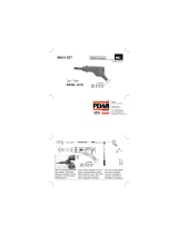
RMM2-DI
Trace-Heating Remote Monitoring Module For Digital Inputs
60 mm
42 mm
15
mm
75
mm
125 mm
DESCRIPTION
The Remote Monitoring Module for Digital Inputs
(nVent RAYCHEM RMM2-DI) provides the capability for the
nVent RAYCHEM NGC controller family to read the status of
devices remotely, like circuit breakers, and can link them back to
the electrical heat-tracing circuits.
The RMM2-DI has in total 15 digital inputs. Multiple RMM2-DI
units can communicate via a single RS485 cable with a single
User Interface, providing centralized monitoring capabilities.
Depending upon the control system selected the number of
RMM2-DI units per system can differ. For technical assistance,
call your local nVent representative or the nVent service center.
RMM2-DI module
Class I, Div2, Groups A, B, C and D Haz Loc
Class I, Zone 2, AEx nA IIC T5
Class I, Zone 2, Ex nA IIC T5 Gc
DEMKO 17 ATEX 1853X IECEx UL 17.0027X II 3 G Ex ec IIC T5 Gc
E490519
Proc. Cont Eq
APPROVALS
RMM2-DI UNIT
Specications
Part number 1244-018083
EAN 5414506018479
Supply voltage (nominal) 115/230 VAC, ±10%, jumper selectable, 50/60 Hz
Power consumption 2,5 VA
Ambient operating range: –40°C to +60°C
Relative humidity: 5 to 95%, noncondensing
Digital Input: 2-wire, 12V, 10 mA minimal output
Digital Input wire connections: 2 x 1.5 mm2 cable
RS-485 connections: Shielded, single twisted pair, max. 1,200 m (~3,900 feet)
Replaceable fuse: F 200 mA/250 V, Wickmann part number 19370-034-K (FAST BLOW)
CONDITIONS OF SAFE USE
The equipment shall only be used in an area of at least pollution degree 2, as defined in EN/IEC 60664-1.

2 | nVent.com
PARTS (SUPPLIED)
INSTALLATION AND CONFIGURATION PROCEDURE RMM2-DI
RMM2-DI LAYOUT
TOOLS REQUIRED
• 7 mm flat-blade screwdriver
• 3 mm flat-blade screwdriver for conductor screws: Torque: min 0.5 NM, max 0.6 NM
• Wire stripper / cutter
• 27 mm spanner (for M20 glands)
• RMM2-DI
• RMM2-DI Trace-heating Remote Monitoring Module for Digital Inputs
• Replacement fuses
• Jumper for voltage selection
This component is an electrical device. It must be installed correctly to ensure proper operation and to prevent frozen pipes,
shock or fire. Read and carefully follow all the installation instructions.
The equipment shall be installed in an enclosure that provides a minimum ingress protection of IP54 in accordance with
EN/IEC 60079-7.
MODBUS ADDRESS
The Modbus address is set via 2 hexadecimal rotary switches. ADDR H is setting the high address number;
ADDR L is for the low address number. See appendix A for conversion between hexadecimal and decimal address range.
WARNING:
WARNING:
XPLOSION HAZARD. DO NOT REMOVE OR REPLACE FUSE WHEN ENERGIZED
RMM2-DI front V1.3_print
DI-1 DI-2 DI-3 DI-4 DI-5 DI-6 DI-7 DI-8 DI-10 DI-11DI-9 DI-12
DI-13 DI-14 DI-15
RS 485
L L
N N
RS 485
ABAS-No: 30609, auf Basis Phoenix EMG 125-LG , Druckfarbe schwarz
Klarsichtdeckel bedruckt, ABAS-No: 30610, auf Basis Phoenix EMG 125-H 15mm klar,
Phoenix EMG 125-LG
Klemmenreihe oben
Druckfarbe: schwarz
Phoenix EMG 125-LG
Klemmenreihe unten
Druckfarbe: schwarz
Bedruckung auf Klarsichtdeckel
Phoenix EMG 125-H 15mm klar
Druckfarbe:
DI-1
- +
DI-2
- +
DI-7
- +
DI-3
- +
DI-4
- +
DI-5
- +
DI-6
- +
DI-8
- +
DI-9
- +
DI-10
- +
DI-11
- +
DI-12
- +
DI-13
- +
DI-14
- +
DI-15
- +
S + -
OUT
S + -
IN
115V:
230V:
Voltage Selector
~
50/60 Hz 1,5VA
E490519
Proc. Cont. Eq.
Class I, Div2, Groups A, B, C and D Haz Loc
Class I, Zone 2, AEx nA IIC T5
Class I, Zone 2, Ex nA IIC T5 Gc
T
amb
DEMKO 17 ATEX 1853X
IECEx UL 17.0027X
II 2 G Ex ec IIC T5 Gc
Fuse: F 200mA, L 250V

nVent.com | 3
INSTALLATION OF POWER SUPPLY AND EARTH WIRING
• Select the voltage operating range. Connect the supplied wire jumpers to the appropriate terminals to select input voltage.
The RMM2-DI is supplied jumpered for 230 volts.
• Connect wiring from power source to designated terminals on RMM2-DI. Use only copper conductors. Connect power cable wires
to the terminals marked L and N on the RMM2-DI. If power is being daisy chained, be sure to maintain polarity of L and N wiring for
incoming and outgoing wires. The terminals accept stranded wires from 0.2 – 2,5 mm2. (0,2 - 4 mm2 solid wire).
INSTALLATION DIGITAL INPUT WIRING
Connect Digital Input cables to the RMM2-DI
Remark: The RMM2-DI has two terminals per Digital input. The Minimum power per DI connection supplied by RMM2-DI module is
12V 10mA (Sink/source). The resistance of the sum of the closed contact plus the resistance of the wire to and
from the contact may not exceed 10 Ohm.
RECORD THE LOCATION/IDENTIFICATION FOR EACH DIGITAL INPUT
RMM2-DI
terminal number Device identication on drawing # Device Tag description
1
2
3
4
5
6
7
8
9
10
11
12
13
14
15
RS-485 MODBUS ADDRESS AND WIRING
SELECT RS-485 ADDRESS AND CONNECT THE RS-485 BUS CABLES
• Each RMM2-DI connected to a RAYCHEM NGC-control and monitoring system must have a unique address; if two RMM2-DIs are
assigned the same address, communication faults will result. To ensure that an unique address to each RMM2-DI unit has been
assigned, apply the following
–
Review the RAYCHEM NGC system layout; if a layout document does not exist, create one. If it has not already been done,
assign an RS-485 address to each RMM2-DI (up to 255)
–
If you are adding one or more RMM2-DI units to an existing RAYCHEM NGC network, confirm that the RS-485 addresses
for existing RMM2-DI units correspond to the system layout. See for details the programming guide of the RAYCHEM NGC
system. By checking the RS-485 addresses on an existing system, you can avoid potential conflicts that would be
confusing and time consuming to troubleshoot otherwise. Record the RS-485 address selected for the Remote Monitoring
Module you are currently installing, and label the exterior of the enclosure with the address assigned to the RMM2-DI.
See for address range and hexadecimal address switch appendix A.

4 | nVent.com
• Do not make connections to the RS-485 bus while it is connected to an operating RAYCHEM NGC network. Damage and/or alarms
could result. The RS-485 bus allows units with unique addresses to be connected together along a common bus. To add a new unit to
the network, simply connect the RS-485 bus from the last unit to the new one, or insert the new unit between two existing units on the
bus. The order in which units are attached to the RS-485 bus does not matter. There are just two constraints on the RS-485 network
–
Each RMM2-DI must be assigned a unique address
–
The RS-485 bus must be a continuous string from the first network device to the last
RMM2-DI in the system.
NOTE
The RS-485 bus operates at 5 V, and equipment connected to it
could be damaged by exposure to higher voltages.
Take precautions to avoid exposing the RS-485 wiring to discharge
of static electricity or other sources of high voltage potential; in particular,
avoid contact with the power supply wiring.
The RMM2-DI has two sets of terminals for connections to the RS-485 bus. One terminal block allows the RMM2-DI to connect to the
RS-485 bus, the second allows a continuation of the bus to other RMM2-DI units on the network. Obs
erve polarity, which is indicated on the RMM2-DI. Connect the incoming RS-485 bus to the set of terminals marked “IN”, observing the
polarity noted on the cover of the RMM2-DI; use the terminal marked “S” for the shielof the RS-485 cab
le. Connect the continuation of the RS-485 bus to the set of terminals marked “OUT” in the same manner (not required for the last RMM2-DI
in the network).
IMPORTANT: Do not connect the shield of the RS-485 cables to the general provided grounding terminal. Connect the shield only to the
RMM2-DI terminals provided. To avoid the potential for spurious ground loops, the RS-485 cable shield should be connected to ground
only in the RAYCHEM unit. For the last RMM2-DI in the network, terminate the RS-485 bus by removing the shorting block on jumper
location from 2–3 and placing it across pins 1–2 (See drawing).
Decimal
Hex
(High, Low) Decimal
Hex
(High, Low) Decimal
Hex
(High, Low) Decimal
Hex
(High, Low) Decimal
Hex
(High, Low)
1 0,1 36 2,4 71 4,7 106 6,A 141 8,D
2 0,2 37 2,5 72 4,8 107 6,B 142 8,E
3 0,3 38 2,6 73 4,9 108 6,C 143 8,F
4 0,4 39 2,7 74 4,A 109 6,D 144 9,0
5 0,5 40 2,8 75 4,B 110 6,E 145 9,1
6 0,6 41 2,9 76 4,C 111 6,F 146 9,2
7 0,7 42 2,A 77 4,D 112 7,0 147 9.3
8 0,8 43 2,B 78 4,E 113 7,1 148 9,4
9 0,9 44 2,C 79 4,F 114 7,2 149 9,5
10 0,A 45 2,D 80 5,0 115 7,3 150 9,6
11 0,B 46 2,E 81 5,1 116 7,4 151 9,7
12 0,C 47 2,F 82 5,2 117 7,5 152 9,8
13 0,D 48 3,0 83 5,3 118 7,6 153 9,9
14 0,E 49 3,1 84 5,4 119 7,7 154 9,A
15 0,F 50 3,2 85 5,5 120 7,8 155 9,B
16 1,0 51 3,3 86 5,6 121 7,9 156 9,C
17 1,1 52 3,4 87 5,7 122 7,A 157 9,D

nVent.com | 5
Decimal
Hex
(High, Low) Decimal
Hex
(High, Low) Decimal
Hex
(High, Low) Decimal
Hex
(High, Low) Decimal
Hex
(High, Low)
18 1,2 53 3,5 88 5,8 123 7,B 158 9.E
19 1,3 54 3,6 89 5,9 124 7,C 159 9,F
20 1,4 55 3,7 90 5,A 125 7,D 160 A,0
21 1,5 56 3,8 91 5,B 126 7,E 161 A,1
22 1,6 57 3,9 92 5,C 127 7,F 162 A,2
23 1,7 58 3,A 93 5,D 128 8,0 163 A,3
24 1,8 59 3,B 94 5,E 129 8,1 164 A,4
25 1,9 60 3,C 95 5,F 130 8,2 165 A,5
26 1,A 61 3,D 96 6,0 131 8,3 166 A,6
27 1,B 62 3,E 97 6,1 132 8,4 167 A,7
28 1,C 63 3,F 98 6,2 133 8,5 168 A,8
29 1,D 64 4,0 99 6,3 134 8,6 169 A,9
30 1,E 65 4,1 100 6,4 135 8,7 170 A,A
31 1,F 66 4,2 101 6,5 136 8,8 171 A,B
32 2,0 67 4,3 102 6,6 137 8,9 172 A,C
33 2,1 68 4,4 103 6,7 138 8,A 173 A,D
34 2,2 69 4,5 104 6,8 139 8,B 174 A,E
35 2,3 70 4,6 105 6,9 140 8,C 175 A,F
176 B,0 192 C,0 208 D,0 224 E,0 240 F,0
177 B,1 193 C,1 209 D,1 225 E,1 241 F,1
178 B,2 194 C,2 210 D,2 226 E,2 242 F,2
179 B,3 195 C,3 211 D,3 227 E,3 243 F,3
180 B,4 196 C,4 212 D,4 228 E,4 244 F,4
181 B,5 197 C,5 213 D,5 229 E,5 245 F,5
182 B,6 198 C,6 214 D,6 230 E,6 246 F,6
183 B,7 199 C,7 215 D,7 231 E,7 247 F,7
184 B,8 200 C,8 216 D,8 232 E,8 248 F,8
185 B,9 201 C,9 217 D,9 233 E,9 249 F,9
186 B,A 202 C,A 218 D,A 234 E,A 250 F, A
187 B,B 203 C,B 219 D,B 235 E,B 251 F,B
188 B,C 204 C,C 220 D,C 236 E,C 252 F,C
189 B,D 205 C,D 221 D,D 237 E,D 253 F,D
190 B,E 206 C,E 222 D,E 238 E,E 254 F,E
191 B,F 207 C,F 223 D,F 239 E,F 255 F, F


©2018 nVent. All nVent marks and logos are owned or licensed by nVent Services GmbH or its aliates. All other trademarks are the property of their respective owners.
nVent reserves the right to change specications without notice.
Raychem-IM-H60195-RMM2DI-EN-1805
nVent.com
North America
Tel +1.800.545.6258
Fax +1.800.527.5703
Europe, Middle East, Africa
Tel +32.16.213.511
Fax +32.16.213.604
Asia Pacific
Tel +86.21.2412.1688
Fax +86.21.5426.3167
Latin America
Tel +1.713.868.4800
Fax +1.713.868.2333
/