Page is loading ...

HANSA
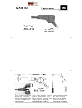
Gas burner HMG
G GB F ESP Art.-Nr.:
1Flammrohr Flame tube Tube de flamme Tube de liama 1329
2Stauscheibe Baffle plats Accroche flamme Deflector con 1331
3Gasdüse 2510
4Doppel-Zündelektrode Double ignition electrode Electrode d´allumage Deflector con 4174
5Gehäuse Box 2010
6Luftmengenregler Air regulator 1681
7Gasdüsenstock kpl. Gas combustion head compl. Ligne de gicleur gaz compléte Cabezal Mezclador de gas compl.
8Gasfeuerungsautomat Gas firing automat Boîte relais gaz automatique Cofre de Seguridad para Q-gas unit 3089
9Motor 230V/50Hz/70W Engine 230V/50Hz/70W Moteur 230V/50Hz/70W Motor 230V/50Hz/70W 3434
10 Luftrad Fanwheel Ventilateur Ventilador 1675
11 Zündtransformator Ignition transformer Transformateur d´allumage Transformador de encendido 3174
12 Luftabschlußklappe air choke Volet d´air Válvula de aire 1673
13 Pressungverstellschieber Pressure slide lever Régulateur de pression Regulador de aire 1674
14 Gas-Kompakteinheit 3722
15 Luftdruckwächter 3762
123
45
6
7
8
9
10
11
12
13
14
15
Seite 1 von 5

Operating Manual
for HMG gasburner
Hansa burners are quality products. Expert installation, regulation/adjustment and servicing/maintenance
provided, our burners will work safely, reliably and economically for many years.
Before the assembly of the burner
the following steps have to be carried out:
Installation and Commissioning
This burner has to be installed and commissioned only by an expert. Therefore locally valid rules and
guidelines are to be strictly observed. He will bear responsibility for the appropriate laying out.
Norms
The following norms have to be considered for safe, environment-friendly and energy-saving running: DIN
4756 gas firing units, DIN 4788 part 2 gas burner with fan ventilation, DIN 4789 connection of atomizing
oil- and gasburner with fan ventilation on heat generators, VDE 0116 elektrical equipment of firing plants.
- Check, whether the heat generator is impermeable on its smoke gas side.
- In case of second hand heat generators the heating surfaces have to be clean in order
to achieve a good degree of effectiveness.
- Gas pipes have to be laid professionally and must be absolutely impermeable.
Content of box:
1 Gasburner HMG 2 Fixing screws M8
1 Operating-Manual mit 2 underlay discs
1 Flange gasket 1 Gasvalve
1 Plug with 7 poles 1 Conic case fixing screw
Assembly:
First you take the burner out of its box and dismantle the burner's bonnet.
Then you loosen the 4 outer screws of the burner case and take the upper part out of the lower part.
Now you fix the lower part to the boiler by means of the flange gasket (pic.1). Fit the upper part to the
lower part again and tighten the four outer screws. Now you assemble the gas valve, the gasket of
which you will also find in the transparent pack. Finally
assemble the gas supply to the gas valve. If gas supply and
electrical connection (euro-plug with 7 poles) is established, the
burner is operational. Please pay attention to the remark relating
to the air blockade on page 5.
Picture1 flange gasket
LK=150
L = 81mm
F = 8,5
page 2 of 5

kW Mcal/h kW 7200 7400 7600 7800 8000 8250 8500 8750 9000 9300 9600 9900
8,37 8,60 8,83 9,06 9,30 9,59 9,88 10,20 10,50 10,90 11,20 11,50
10,0 8,6 11,1 1,3 1,3 1,3 1,2 1,2 1,2 1,1 1,1 1,1 1,0 1,0 1,0
12,0 10,3 13,3 1,6 1,5 1,5 1,5 1,4 1,4 1,3 1,3 1,3 1,2 1,2 1,2
14,0 12,,8 15,6 1,9 1,8 1,8 1,7 1,7 1,6 1,6 1,5 1,5 1,4 1,4 1,4
16,0 13,8 17,8 2,2 2,1 2,0 2,0 1,9 1,9 1,8 1,8 1,7 1,6 1,6 1,5
18,0 15,5 20,0 2,4 2,3 2,3 2,2 2,2 2,1 2,0 2,0 1,9 1,9 1,8 1,7
20,0 17,2 22,2 2,7 2,6 2,5 2,5 2,4 2,3 2,3 2,2 2,1 2,1 2,0 1,9
23,0 19,8 25,6 3,1 3,0 2,9 2,8 2,8 2,7 2,6 2,5 2,4 2,4 2,3 2,2
26,0 22,4 28,9 3,5 3,4 3,3 3,2 3,1 3,0 2,9 2,8 2,8 2,7 2,6 2,5
29,0 24,9 32,2 3,8 3,7 3,6 3,6 3,5 3,4 3,3 3,2 3,1 3,0 2,9 2,8
32,0 27,5 35,6 4,2 4,1 4,0 3,9 3,8 3,7 3,6 3,5 3,4 3,3 3,2 3,1
36,0 31,8 40,0 4,8 4,6 4,5 4,4 4,3 4,2 4,1 3,9 3,8 3,7 3,6 3,5
40,0 34,4 44,4 5,3 5,2 5,0 4,9 4,8 4,6 4,5 4,4 4,3 4,1 4,0 3,9
45,0 38,7 50,0 6,0 5,8 5,7 5,5 5,4 5,2 5,1 4,9 4,8 4,6 4,5 4,3
50,0 43,0 55,6 6,6 6,5 6,3 6,1 6,0 5,8 5,6 5,5 5,3 5,1 5,0 4,8
Gas flow table
page 3 of 5
IMPORTANT!!
Measured values relate to 36 seconds, not (as usual) to 60 seconds
Performance table
Type Performance Nozzle pressure Measurement X Air choke Air blockage
HMG kW mbar
HMG 12 2,8 0 1 yes
HMG 15 4 0 2 yes
HMG 20 5 0 3 yes
HMG 25 6,5 0 5 yes
HMG 30 8,5 1 6 yes
HMG 30 8,5 1 1 no
HMG 35 12 1 5 no
HMG 37 14 3 6 no
Important!!!
From a performance of 28 kW and more
or if the burner pulsates please remove
the air-blockade !!

Seite 4 von 5
Description and explanation of function of Dung's compact unit GB-(LEP) 055D01

The air amount regulator determines the position of
the air choke. For exact data on performance
have a look at performance table on page 3
Guarantee:
The type HMG is a trade mark fabricate. Guarantee for additional parts is 12 months after setting into
operation, with a maximum term of 15 months after the dispatch. The burner has to be installed,
assembled and metered professionally. In case of non compliance with the aforementioned conditions,
faulty handling or wrong connections, the guarantee expires.
Electrical Connection
Connecting of the 7(4) pole plug is done according to VDE 0116 and the electrical wiring
diagram on page 5.
Furthermore it is essential to take care of correct polarity of the Euro-plugs connecting boiler and
b
urner (check of phasing)
If this instruction is not heeded, this will automatically lead to abortion of the program of the
automatic gas firing unit after its safety time because no ionisation current is created.
Electrical circuit diagram:
Seite 5 von 5
Air amount regulator Field of operation
/