INSTALLATION
BEFORE INSTALLING THIS PRODUCT…
Read these instructions carefully. Failure to follow the instructions
could damage the product and void the warranty. Ensure that the
installer is a trained, experienced service technician. After completing
installation, use these instructions to check product operation.
LOCATION
INSTALLATION CONSIDERATIONS
Install Zone Dampers (ZDS) or (ZDB) into a squared air duct. Frame
misalignment may jam the damper blades. Do not weld dampers to air
ducts.
INSTALLING A ZONE DAMPER
Ensure the ZD is correctly sized to the air duct and select a ZD location
plenum and in the air duct takeoff to the zone. Always make sure the
dampers are accessible for wiring, checkout, duct cleaning and
replacement of damper or motor if ever needed.
DAMPER SIZE
To ensure proper operation, the ZD must be properly sized for the air
duct. To ensure proper fit, damper sizes are built slightly smaller. ¼”
less than the listed dimensions. If the damper is forced into an
undersized air duct, the excess pressure jams the damper blades and
causes improper operation.
.
1. Cut a 4-inch (102-millimeter) opening in one side (shorter dimension)
of the air duct at the location selected. Ensure the opening is cut fully to
the top and bottom air duct seams.
2. Slide the ZDS into the cut opening of the air duct. Ensure the electric
actuator is mounted toward the top of the air duct.
3. Secure the ZDS mounting plate to the air duct with the sheet metal zip
screws provided.
CAUTION
Do not install dampers in heating systems where spray or atomizing
type humidifiers are installed in the furnace plenum or air supply duct.
Excessive lime or mineral deposits accumulate on damper blades
and cause improper operation. For humidification, use evaporative
type humidifiers or return air type humidifiers.
and Checkout.
Never force dampers into undersized air ducts. Excess pressure will jam
damper blades.
Ensure high limit setting is 200qF(93qC) or lower. Higher settings can
damage electric actuator.
NEVER FORCE OR MOVE DAMPER BLADES MANUALLY. This can
strip the motor gears and void the warranty.
ALL WIRING MUST CONFORM TO NEC STANDARDS AND ALL
APPLICABLE LOCAL CODES.
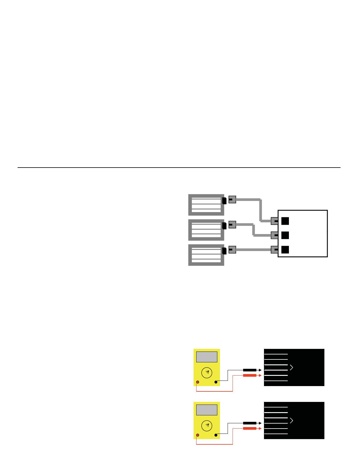
TheZDPdamperisthesimplestdamperintheworldtowire.Just
plug it in to the female receptacle on the control panel. The damper
comes complete with a 25’ Modular Cord with an RJ11 connector on
each end and a two-line splitter for slaving additional dampers from
the same zone. Up to 10 dampers can be controlled on one zone.
WIRING DIAGRAM
Plug-In Zone Panel
Plug-In Zone Dampers
ZONE 1
,
wire in one damper to the control panel and check its operation.
Once the first damper operation is checked, add one damper at a
time using the splitter supplied with each damper and check each
damper as it is added to the zone.
The Plug-In Motors operate on 12VDC and require very little current.
The modular cords supplied are standard telephone wire (four
conductor) with RJ11 jacks.
Upon plugging in the damper from the panel the damper the damper
ZONE 2
ZONE 3
To check the damper operation, place all thermostats to OFF or not calling.
All dampers should be open with their LEDs Green. Press and HOLD the
BOOT button on the zoning panel. All dampers will go closed and the LEDs
turn RED. Release the Boot button and all dam
ers will return to O
en.
,
the panel is telling the damper to Open. Check the zone on the panel
to see if the zone indicator is lit Green also. If the Zone indicator is
OFF, the damper will move to the Closed position and the damper
LED will turn RED, indicating the damper is Closed.
CHECKOUT
The ZDP damper is a very simple damper to checkout. The two (2)
If the damper is not operating properly, check the output jack
on the panel for 12VDC. See below. If the panel is providing
12VDC (+/-10%), check the plug on the end of the modular
cable for 12VDC to ensure the wire and modular plugs have
the same power.
co
o
on
emo
o
prov
es
n
ca
on o
e
ampe
pos
on.
When the LED is GREEN the Damper is Open. When the LED is
RED the damper is CLOSED. The motor is powered by 12VDC and
uses a four (4) conductor cord to provide the power.
REPLACEMENT MOTOR
To replace the motor, simply loosen and remove the screw holding
the motor onto the damper. Pull the motor straight off the damper
shaft. Please note this is a snug fit and pull straight up. Before
putting new motor back on, plug-in replacement to ensure the
MOTOR PLUG
+12VDC
NOT USED
NOT USED
POSITIVE (+)
POSITIVE (+)
NEGATIVE (-)
VDC
DAMPER OPEN
MOTOR PLUG
+12VDC+12VDC
NOT USED
NOT USED
POSITIVE (+)
POSITIVE (+)
NEGATIVE (-)
VDC
DAMPER OPEN
pos
on
emo
o
s
n,
pen o
ose
.
esure
oa
gn
e
damper to the same position as the motor before placing the new
motor back onto the damper shaft. Replace mounting screw.
Questions, Comments, Problems??? Call our Toll Free Answer
Line at:
1-800-422-4328 ext. 2
-12VDC
NOT USED
NOT USED
POSITIVE (+)
POSITIVE (+)
NEGATIVE (-)
VDC
DAMPER CLOSED
-12VDC-12VDC
NOT USED
NOT USED
POSITIVE (+)
POSITIVE (+)
NEGATIVE (-)
VDC
DAMPER CLOSED
2


