ATTENTION INSTALLER
Read this installation template before installing humidifier.
Warranty is void unless humidifier is installed by qualified
heating and air conditioning contractor due to possible
misapplication of product. This product must be installed in
compliance with all local, state, and federal codes. Proper
humidification and humidity control require that the home be
constructed with local codes and good building practices.
WARNING
ELECTRICAL SHOCK HAZARD. Disconnect power to the
furnace before installing humidifier.
CAUTION
SHARP EDGES. Use care when cutting and handling
ductwork.
HOT WATER CAN SCALD. Shut o hot water supply
before tapping into hot water supply.
NOTICE
FREEZING TEMPERATURES CAN BURST WATER PIPES.
• Do not install humidifier where freezing may occur.
CONDENSATION DAMAGE OR MOLD CAN OCCUR.
• Locate return duct mounted humidifier control at least
6" upstream of humidifier, bypass duct connection, or
fresh air intake for accurate humidity sensing.
• Locate wall mount humidifier control in areas
unaffected by drafts or heat sources for accurate
humidity sensing.
• Reduce the setting on the humidifier control if
condensation forms on windows or in unheated spaces.
EQUIPMENT DAMAGE MAY OCCUR.
• Do not install humidifier or bypass connection on the
furnace jacket.
• Do not connect the transformer to the blower motor
wiring.
• Do not install the humidifier or bypass connection on a
plenum face at the blanked end of the cooling coil.
• If water pressure exceeds 125 psi, reduce water pressure
with devices allowed by local codes.
• Do not use water with temperature greater than 140°F.
• Do not install humidifier on systems with differential
pressure greater than 0.4 w.g. between the supply and
return plenums.
• When installing the humidifier control on the return
duct of a downflow furnace, ensure the blower
continues to run after a heat call is satisfied.
SPECIFICATIONS
Humidifier Dimensions:
Width (including solenoid valve): 15-3/8"
Height (including drain spud): 15-3/4"
Depth: 10-1/4"
Bypass Duct Opening: 6" diameter
Plenum Opening: 10"W x 12-3/4"H
Water Feed Rate: 3 gph
Electrical Data: 24 VAC, 60 Hz, 0.5 Amp
Water Panel®: Model 35
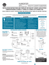
INSTALLATION OPTIONS (LEFT HAND DISCHARGE SHOWN)
Aprilaire® Model 600 and 600M can be installed on either the supply plenum or cold air return of a forced air handling system with right
hand or left hand bypass duct connections. The humidifier dimensions and serviceability must be considered when selecting the best
location for the humidifier.
Hot water is recommended (140°F max) to provide maximum evaporative capacity. It is also recommended when the Blower Activation
Feature is used with an Automatic Digital Humidifier Control, or on a heat pump system. The humidifier functions with cold, hot,
softened, or unsoftened water.
FURNISHED ITEMS
• Humidifier with built-in bypass damper
• 24 VAC transformer
• Automatic Digital Humidifier Control and
Outdoor Temperature Sensor (Model 600 only)
• Manual Humidifier Control (Model 600M only)
• Humidifier Control Installation Instructions
• Saddle valve
• Humidifier Installation Template
ITEMS NOT FURNISHED
• Mounting screws (sheet metal screws)
• Water supply line (1/4" O.D. copper)
• Drain line (1/2" I.D. hose)
• Low voltage wire
• Bypass ductwork
• Model 50 current sensing relay
(if required)
PARTS LIST
8
7
2
10
12
4
5
3
1
11
6
9
1. Front Cover
2. Base
3. Feed Tube
4. Water Distribution Tray
5. Water Panel®
6. Scale Control Insert
7. Integral Damper
8. Damper Handle
9. Drain Spud
10. Hole Plug
11. Nameplate
12. Solenoid Valve
Return
Floor Drain or
Condensate
Pump
Drain Line
Floor Drain or
Condensate
Pump
Return
Supply
Supply
Floor Drain or
Condensate
Pump
Drain Line
Condensate
Pump
HORIZONTALUPFLOW
90-1079
TEMPLATE MUST BE LEVEL
90-1250
Model 600 Series Humidifier Template