SMC ISE40G Series User manual

Category
Measuring, testing & control
Type
User manual

SMC ISE40G Series: Your Compact, Precise Digital Pressure Switch for a Wide Range of Applications

The SMC ISE40G Series is a compact, high-precision digital pressure switch designed for a variety of industrial applications. With its wide pressure range, flexible output options, and accuracy of up to ±0.5% F.S., it provides reliable pressure measurement and control. The intuitive 3-screen display, including a main display and two sub-displays, offers clear and detailed information on pressure measurements, set values, and error codes.

ISE7#G-TF2Z015EN
Page 1 of 2
Instruction Manual
High Precision Digital Pressure Switch
ISE70G / ISE75G / ISE76G / ISE77G
The intended use of the pressure switch is to measure the pressure of
fluid and to provide an output signal.
1 Safety Instructions
These safety instructions are intended to prevent hazardous situations
and/or equipment damage. These instructions indicate the level of
potential hazard with the labels of “Caution,” “Warning” or “Danger.”
They are all important notes for safety and must be followed in addition
to International Standards (ISO/IEC)
*1)
, and other safety regulations.
*1)
ISO 4414: Pneumatic fluid power - General rules relating to systems.
ISO 4413: Hydraulic fluid power - General rules relating to systems.
IEC 60204-1: Safety of machinery - Electrical equipment of machines.
(Part 1: General requirements)
ISO 10218-1: Manipulating industrial robots -Safety. etc.
Refer to product catalogue, Operation Manual and Handling
Precautions for SMC Products for additional information.
Keep this manual in a safe place for future reference.
Caution Caution indicates a hazard with a low level of risk which, if
not avoided, could result in minor or moderate injury.
Warning Warning indicates a hazard with a medium level of risk
which, if not avoided, could result in death or serious injury.
Danger Danger indicates a hazard with a high level of risk which, if
not avoided, will result in death or serious injury.
Warning
Always ensure compliance with relevant safety laws and
standards.
All work must be carried out in a safe manner by a qualified person in
compliance with applicable national regulations.
This product is class A equipment intended for use in an industrial
environment. There may be potential difficulties in ensuring
electromagnetic compatibility in other environments due to conducted
or radiated disturbances.
Do not disassemble, modify (including changing the printed
circuit board) or repair.
An injury or failure can result.
Do not operate the product outside of the specifications.
Do not use for flammable or harmful fluids.
Fire, malfunction or damage to the product can result.
Do not operate in an atmosphere containing flammable or
explosive gases.
Fire or an explosion can result.
This product is not designed to be explosion proof.
If using the product in an interlocking circuit:
Provide a double interlocking system, for example a mechanical
system.
Check the product for correct operation.
Otherwise malfunction can result, causing an accident.
Do not touch terminals and connectors while the power is on.
Otherwise electric shock, malfunction or product damage can result.
Refer to the operation manual on the SMC website (URL:
https://www.smcworld.com) for more safety instructions.
2 Specifications
2.1 General specifications
2.2 IO-Link specifications
IO-Link type Device
IO-Link version V1.1
Communication speed COM2 (38.4 kbps)
Min. cycle time 2.3 ms
Process data length Input Data: 2 byte, Output Data: 0 byte
On request data comms. Available
Data storage function Available
Event function Available
Vendor ID 131 (0x0083)
Device ID
ISE70G--L2- : 309 (0x0135)
ISE75G--L2- : 320 (0x0140)
ISE76G--L2- : 321 (0x0141)
ISE77G--L2- : 322 (0x0142)
Special products (-X) might have specifications different from those
shown in this section. Contact SMC for specific drawings.
3 Names of Individual parts
3.1 Product
3.2 Display
4 Installation
4.1 Installation
Warning
Do not install the product unless the safety instructions have been read
and understood.
4.2 Environment
Warning
Do not install in a location subject to vibration or impact in excess of
the product’s specifications.
Do not mount in a location exposed to radiant heat that would result in
temperatures in excess of the product specification.
4.3 Mounting with Bracket
Mount the bracket to the product using mounting screws supplied (M4x6
L (2 pcs)) then set the product in the required position.
Tighten the bracket mounting screws to a torque of 0.76 ±0.1 N•m.
Bracket A (Part No. ZS-50-A) Bracket B (Part No. ZS-50-B)
4 Installation (continued)
4.4 Mounting with Orifice
4.5 Piping
Caution
Before connecting piping make sure to clean up chips, cutting oil, dust
etc.
After hand tightening, tighten the fitting using a spanner on the flat
surfaces of the fitting (24 mm A/F).
When tightening, do not hold the upper part of the product (display)
with the spanner.
For Rc1/4 and NPT1/4 threads the tightening torque must be 8 to 12
N•m. For G1/4 thread the tightening torque must be 4 to 5 N•m.
4.6 Display Rotation
During installation, the upper part (display) of the product can be
rotated by 336°. Take care as rotating the display with excessive force
will damage the end stopper.
4.7 Wiring
Connections should be made with the power supply turned off.
Use a separate route for the product wiring and any power or high
voltage wiring. Otherwise, malfunction may result due to noise.
If a commercially available switching power supply is used, be sure to
ground the frame ground (FG) terminal. If a switching power supply is
connected, noise will be superimposed and will not meet the product
specifications.
Insert a noise filter such as a line noise filter/ferrite between the
switching power supplies or change the switching power supply to the
series power supply.
ORIGINAL INSTRUCTIONS
24 mm
across
flats
S
p
anne
Upper part of
product
M4x6L M4x6L
Bracket A Bracket B
Product No. ISE70G ISE75G ISE76G ISE77G
Applicable fluid Fluids and Gases (non corrosive)
Pressure
Rated pressure range 0 to 1.00
MPa
0 to 2.00
MPa
0 to 5.00
MPa
0 to 10.0
MPa
Display / set pressure
range
-0.105 to
1.050
MPa
-0.105 to
2.100
MPa
-0.25 to
5.25
MPa
-0.50 to
10.50
MPa
Minimum setting unit 0.001 MPa 0.01 MPa
Proof pressure 3.0 MPa 5.0 MPa
12.5 MPa
30 MPa
Electrical
Power supply as
switch output device
12 to 24 VDC ±10% with 10%
Voltage ripple or less (p-p)
Power supply as
IO-Link device
18 to 30 VDC, including 10%
voltage ripple (p-p)
Current consumption 35 mA or less
Protection Polarity protection
Accuracy
Display accuracy ±2% F.S.±1 digit (at ambient 25±3
o
C)
Repeatability ±0.5% F.S.
Temp. characteristics
(25
o
C standard) ±3% F.S. ±5% F.S.
Switch output
Output type NPN or PNP open collector output.
Output mode Hysteresis mode, window comparator
mode, error or switch output OFF.
Switch operation Normal or reversed output.
Max. Load current 80 mA
Max. Applied voltage 30 V (NPN output)
Internal voltage drop
(Residual voltage) 1.5 V or less (Load current 80 mA)
Delay time 2.0 ms or less (for anti-chatter function:
variable at 0 to 60 s / 0.01 step)
Hysteresis or Window
comparator mode Variable from 0
Short circuit
protection Provided
Display
Units MPa, kPa, kgf/cm
2
, bar, psi
Display type LCD
Number of displays 3-screen display (Main display,
sub display x 2)
Display colour Main display: Red/Green,
Sub display: Orange
Number of display
digits
Main display: 4 digits (7-segments)
Sub display: 4 digits (Upper 1 digit 11-
segments, 7-segments for other)
Operation light LED is ON when switch output is ON
(OUT1, OUT2: Orange)
Digital filter Variable from 0 to 30 s / 0.01 step
Orifice
(Part no. ZS-48-A)
Tighten the orifice to a
torque of 1.5 ±0.1 N•m.
Power supply / Output
connector
(
M12
p
lu
g)
Displa
y
Fitting
(
24 mm across flats
)
Part Description
Operation Light Displays the switch operating condition
Main display Displays pressure measurement values and
error codes (2 colour display).
Sub display (left) Displays items (Orange)
Sub display (right) Displays set values, peak and bottom values.
(Orange)
UP button Increases mode and ON/OFF set values.
DOWN button Decreases mode and ON/OFF set values.
SET button Changes the mode and confirms the settings.
IO-Link status
indicator light
Displays OUT1 output communication status
(SIO mode, start-up mode, operation mode) and
the presence of communication data.
ISE7#G-TF2Z015EN
Page 2 of 2
Product code is dis
p
la
y
ed for 3 seconds
[Measurement mode]
Detects the pressure and indicates the display and switch operating
status. This is the basic mode; other modes should be selected for
set-point changes and other function settings.
Measurement Mode display
Sub display
In measurement mode, the sub display can be temporarily changed
by pressing the UP or DOWN buttons.
: Arbitrary display mode can be added to the sub display by setting
the [F10] sub display. If the sub display is changed during arbitrary
display setting, the display will return to arbitrary display after 30 s.
(The default setting does not include arbitrary display).
4 Installation (continued)
How to use connector
Align the cable connector key groove with the product connector key
to insert and rotate the knurled part of the connector.
Connect the wires of the lead wire to the M12 connector as shown
below.
M12 Connector (code A)
1) When used as a switch output device
No. Name Colour Function
1 DC(+) Brown 12 to 24 VDC
2 OUT2 White Switch output 2
3 DC(-) Blue 0 V
4 OUT1 Black Switch output 1
2) When used as an IO-Link device
No. Name Colour Function
1 L+ Brown 18 to 30 VDC
2 DO White Switch output 2
3 L- Blue 0 V
4 C/Q Black
Communication
data (IO-Link) /
Switch output 1
(SIO)
5 Setting (Measurement mode)
Power is supplied
6 Pressure Setting
Default settings
When the pressure exceeds the set value, the switch will be turned ON.
When the pressure falls below the set value by the amount of hysteresis
or more, the switch will be turned OFF.
The default setting is to turn ON the pressure switch when the pressure
reaches the centre of the atmospheric pressure and upper limit of the
rated pressure range. If this condition is acceptable, then keep these
settings.
7 3 Step Setting mode
3 step setting mode (hysteresis mode)
In 3 step setting mode, the set value (P_1 or n_1) and hysteresis (H_1)
can be changed. Set the items on the sub display (set value or
hysteresis) using the UP and DOWN button. When changing the set
value, follow the operation below. The hysteresis setting can be
changed in the same way.
(1) Press the SET button once when
the item to be changed is shown
on the sub display. The set value
on the sub display will start
flashing.
(2) Press the UP or DOWN button to
change the set value.
When the UP and DOWN buttons are pressed and held
simultaneously for 1 second or longer, the set value is displayed as
[- - -], and the set value will be the same as the current pressure value
automatically (snap shot function).
Afterwards, it is possible to adjust the value by pressing the UP or
DOWN button.
(3) Press the SET button to complete the setting.
The Pressure switch turns on within a set pressure range (from P1L to
P1H) during window comparator mode. Set P1L, the lower limit of the
switch operation, and P1H, the upper limit of the switch operation and
WH1 (hysteresis) following the instructions given above.
(When reversed output is selected, the sub display (left) will indicate [n1L]
and [n1H].)
Set OUT2 in the same way.
Setting of the normal/reverse output switching and hysteresis/window
comparator mode switching are performed using the function selection
mode [F 1] OUT1 setting and [F 2] OUT2 setting.
8 Simple Setting mode
(1) Press and hold the SET button between 1 and 3 seconds in
measurement mode. [SEt] is displayed on the main display. When
the button is released while in the [SEt] display, the current pressure
value is displayed on the main display, [P_1] or [n_1] is displayed on
the sub display (left), and the set value is displayed on the sub display
(right) (Flashing).
(2) Change the set value using the UP and DOWN button,
and press the SET button to set the value. Then, the
setting moves to hysteresis setting. (The snap shot
function can be used).
(3) Change the set value with the UP or DOWN button,
and press the SET button to set the value. Then, the setting moves
to the delay time of the switch output. (The snap shot function can be
used).
(4) The delay time of the switch output can be selected by pressing the
UP or DOWN button at the ON and OFF point of the switch output.
Delay time setting can prevent the output from chattering.
The delay time can be set in the range 0.00 to 60.00 sec. in 0.01 sec.
increments.
8 Simple Setting mode (continued)
(5) Press the SET button for less than 2 seconds to complete the OUT1
setting. [P_2] or [n_2] is displayed on the sub screen (left). Continue
with setting OUT2.
Press and hold the SET button for 2 seconds or longer to complete
the setting. The product will return to measurement mode.
In window comparator mode, set P1L, the lower limit of the switch
operation, and P1H, the upper limit of the switch operation, WH1
(hysteresis) and dtH / dtL (delay time) following the instructions given
above. (when reversed output is selected, the sub display (left) will
indicate [n1L] and [n1H]).
Set OUT2 in the same way.
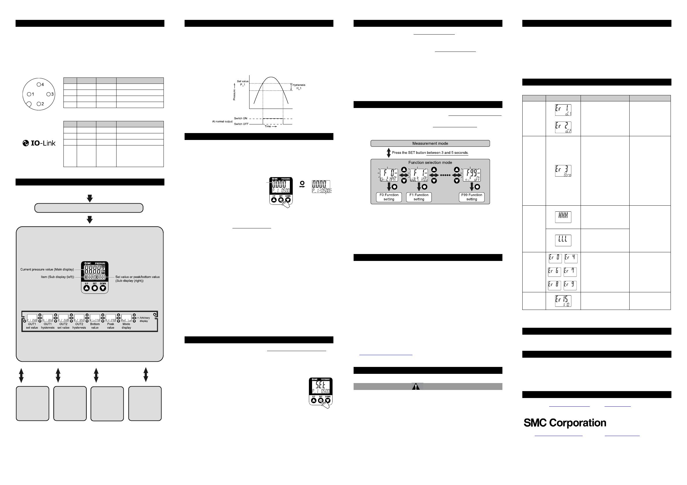
9 Function Selection mode
In measurement mode, press the SET button between 3 and 5 seconds
to display [F 0]. Select to display the function to be changed [F□□].
Press and hold the SET button for 2 seconds or longer in function
selection mode to return to measurement mode.
: Some products do not have all of the functions. If a function is not
available or selected due to configuration of other functions, [- - -] is
displayed on the sub display.
10 Other Settings
Peak / Bottom value display
The max. (min.) pressure from when power is supplied is detected and
monitored. The value can be displayed on the sub display by pressing
the UP or DOWN button in measurement mode.
Snap Shot function
The current pressure value can be stored to the switch output ON/OFF
set point. When the set value and hysteresis are set, press the UP and
DOWN button for 1 s or longer simultaneously. Then the set value of the
sub display (right) shows [---], and the values corresponding to the
current pressure values are automatically displayed.
Zero-clear function
In measurement mode, when the UP and DOWN buttons are pressed for
1 s or longer simultaneously, the main display shows [---] and then will
reset to zero. The display will return to measurement mode automatically.
Refer to the operation manual on the SMC website (URL:
https//www.smcworld.com) for further details of how to set these and
other functions.
11 Maintenance
11.1 General Maintenance
Caution
Not following proper maintenance procedures could cause the product
to malfunction and lead to equipment damage.
If handled improperly, compressed air can be dangerous.
Maintenance of pneumatic systems should be performed only by
qualified personnel.
Before performing maintenance, turn off the power supply and be sure
to cut off the supply pressure. Confirm that the air is released to
atmosphere.
After installation and maintenance, apply operating pressure and
power to the equipment and perform appropriate functional and
leakage tests to make sure the equipment is installed correctly.
11 Maintenance (continued)
How to reset the product after power cut or forcible de-energizing
The setting of the product will be retained as it was before a power cut or
de-energizing. The output condition is also basically recovered to that
before a power cut or de-energizing, but may change depending on the
operating environment.
Therefore, check the safety of the whole installation before operating the
product. If the installation is using accurate control, wait until the product
has warmed up (approximately 10 to 15 minutes).
12 Troubleshooting
12.1 Error Indication
If the error cannot be reset after the above measures are taken, or errors
other than the above are displayed, please contact SMC.
13 Limitations of Use
13.1 Limited warranty and Disclaimer/Compliance Requirements
Refer to Handling Precautions for SMC Products.
14 Product Disposal
This product shall not be disposed of as municipal waste. Check your
local regulations and guidelines to dispose this product correctly, in order
to reduce the impact on human health and the environment.
15 Contacts
Refer to www.smcworld.com or www.smc.eu for your local
distributor/importer.
URL : https://www.smcworld.com (Global) https://www.smc.eu (Europe)
SMC Corporation, 4-14-1, Sotokanda, Chiyoda-ku, Tokyo 101-0021, Japan
Specifications are subject to change without prior notice from the manufacturer.
© 2021 SMC Corporation All Rights Reserved.
Template DKP50047-F-085M
Error Error displayed Description Measures
Over
current
error
The load current
applied to the switch
output has exceeded
the maximum value.
Turn the power off
and remove the
cause of the over
current.
Then supply the
power again.
Residual
pressure
error
During zero clear
operation, pressure
greater than ±7% F.S.
is present. Note that
the mode is returned
to measurement mode
automatically
1 s later. The zero
clear range varies by
±1% F.S. due to
variation between
individual products.
Release the
applied pressure to
atmosphere, and
retry the zero clear
operation.
Pressurize
error
Pressure exceeding
the upper limit of the
set pressure range is
applied.
Reset applied
pressure to a level
within the set
pressure range.
Pressure exceeding
the lower limit of the
set pressure range is
applied.
System
error
Displayed if an internal
data error has
occurred.
Turn the power off
and on again.
If the failure cannot
be solved, contact
SMC.
Version
does not
match
Version of master and
IO-Link
does not match.
Align the master
IO-Link version to
the device.
Press the
SET button
once
Press the
SET button
for 1 to 3 s
Press the
SET button
for 3 to 5 s
[3 step
setting
mode]
Set value or
hysteresis
[Simple
setting
mode]
Set value,
hysteresis and
delay time
[Function
selection
mode]
Change the
function
settings
[Other
settings]
Zero clear
Snap lock
Key Lock
  • Page 1 1
  • Page 2 2

SMC ISE40G Series User manual

Category
Measuring, testing & control
Type
User manual

SMC ISE40G Series: Your Compact, Precise Digital Pressure Switch for a Wide Range of Applications

The SMC ISE40G Series is a compact, high-precision digital pressure switch designed for a variety of industrial applications. With its wide pressure range, flexible output options, and accuracy of up to ±0.5% F.S., it provides reliable pressure measurement and control. The intuitive 3-screen display, including a main display and two sub-displays, offers clear and detailed information on pressure measurements, set values, and error codes.

Ask a question and I''ll find the answer in the document

Finding information in a document is now easier with AI