Jenn-Air JUC2450ACX User manual
- Category
- Wine coolers
- Type
- User manual
This manual is also suitable for

Wine Cellar
Under Counter
Refrigerator
This Base Manual covers general information
Refer to individual Technical Sheet
for information on specific models
This manual includes, but is
not limited to the following:
Jenn-Air
JWC2450ARB
JWC2450ARW
JWC2450ARS
JWC2450ACX
JUC2450ARB
JUC2450ARW
JUC2450ARS
JUC2450ACX
Service
This manual is to be used by qualified appliance
technicians only. Maytag does not assume any
responsibility for property damage or personal
injury for improper service procedures done by
an unqualified person.
16022323
July 2003

2 16022323 Rev. 0 ©2003 Maytag Appliances Company
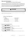
Important Notices for Servicers and Consumers
Maytag will not be responsible for personal injury or property damage from improper service procedures. Pride and
workmanship go into every product to provide our customers with quality products. It is possible, however, that
during its lifetime a product may require service. Products should be serviced only by a qualified service technician
who is familiar with the safety procedures required in the repair and who is equipped with the proper tools, parts,
testing instruments and the appropriate service information. IT IS THE TECHNICIAN’S RESPONSIBILITY TO
REVIEW ALL APPROPRIATE SERVICE INFORMATION BEFORE BEGINNING REPAIRS.
!WARNING
To avoid risk of severe personal injury or death, disconnect power before working/servicing on appliance to avoid
electrical shock.
To locate an authorized servicer, please consult your telephone book or the dealer from whom you purchased this
product. For further assistance, please contact:
Customer Service Support Center
CAIR Center
Web Site Telephone Number
WWW.AMANA.COM ............................................... 1-800-843-0304
WWW.JENNAIR.COM ............................................ 1-800-536-6247
WWW.MAYTAG.COM............................................. 1-800-688-9900
CAIR Center in Canada.......................................... 1-800-688-2002
Amana Canada Product .......................................... 1-866-587-2002
Recognize Safety Symbols, Words, and Labels
DANGER
!
DANGER—Immediate hazards which WILL result in severe personal injury or death.
WARNING
!
WARNING—Hazards or unsafe practices which COULD result in severe personal injury or death.
CAUTION
!
CAUTION—Hazards or unsafe practices which COULD result in minor personal injury, product or property
damage.
Important Information

©2003 Maytag Appliances Company 16022323 Rev. 0 3
Important Information ................................................... 2
Model Identification .................................................... 4
Component Testing
Compressor ............................................................. 5
Capacitor ................................................................. 6
Condenser ............................................................... 6
PTC Relay ............................................................... 7
(SSAC) Electronic Control ....................................... 7
Condenser Motor ..................................................... 7
Cabinet Light Switch ................................................ 7
Drier......................................................................... 7
Evaporator................................................................ 8
Thermistor................................................................ 8
Troubleshooting...................................................... 9-13
Disassembly Procedures
Replacing the Evaporator ....................................... 14
Compressor Removal ............................................. 14
Compressor Installation ......................................... 14
Condenser Removal ............................................... 15
Condenser Installation............................................ 15
Condenser Fan Removal ........................................ 15
Evaporator Thermistor Removal .............................. 15
Evaporator Thermistor Installation .......................... 15
Wiring Diagram ...................................................... 16
Appendix A
Wine Cellar Owners Guide ....................................A-1
Appendix B
Under Counter Refrigerator Owners Guide .............B-1
Table of Contents

4 16022323 Rev. 0 ©2003 Maytag Appliances Company
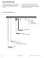
Model Identification
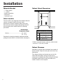
Wine Cellar / Under Counter models vary in trim and
accessories, but all models have the same basic
construction. "Operating Instructions" and "Service
Instructions" apply to all cabinets unless stated
otherwise.
For positive identifications of individual units, state
complete serial number, model, and type. This
information is found on the serial plate located on front
upper right hand corner of foodliner or on some models,
exterior back of the outer casing.
Jenn-Air Model Identification
J WC 2 4 5 0 AR W
Color
W White
B
Black
S
Stainless
X
Accepts Panel
Special Features
Dimensions
24
Inches Wide
Product
WC
Wine Cellar
UC Under Counter Refrigerator
Jenn-Air

Component Testing
!WARNING
To avoid risk of electrical shock, personal injury, or death, disconnect electrical power source to unit, unless test
procedures require power to be connected. Discharge capacitor through a resistor before attempting to service.
Ensure all ground wires are connected before certifying unit as repaired and/or operational.
©2003 Maytag Appliances Company 16022323 Rev. 0 5

Component Testing
!WARNING
To avoid risk of electrical shock, personal injury, or death, disconnect electrical power source to unit, unless test
procedures require power to be connected. Discharge capacitor through a resistor before attempting to service.
Ensure all ground wires are connected before certifying unit as repaired and/or operational.
6 16022323 Rev. 0 ©2003 Maytag Appliances Company
Component Description Test Procedures

Component Testing
!WARNING
To avoid risk of electrical shock, personal injury, or death, disconnect electrical power source to unit, unless test
procedures require power to be connected. Discharge capacitor through a resistor before attempting to service.
Ensure all ground wires are connected before certifying unit as repaired and/or operational.
©2003 Maytag Appliances Company 16022323 Rev. 0 7
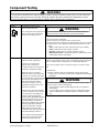
Compressor
When compressor electrical circuit is
energized, the start winding current
causes relay to heat. After an amount of
starting time, the start winding circuit
turns off. The relay will switch off the
start winding circuit even though
compressor has not started (for
example, when attempting to restart
after momentary power interruption).
With “open” relay, compressor will not
start because there is little or no current
to start windings. Overload protection
will open due to high locked rotor run
winding current.
With “shorted” relay or capacitor,
compressor will start and overload
protector will quickly open due to high
current of combined run and start
windings.
With open or weak capacitor,
compressor will start and run as normal
but will consume more energy.
Resistance test
1. Disconnect power to unit.
2. Discharge capacitor by shorting across terminals with a resistor for 1
minute.
NOTE: (Some compressors do not have a run capacitor.)
3. Remove leads from compressor terminals.
4. Set ohmmeter to lowest scale.
5. Check for resistance between
Terminals “S” and “C”, start winding
Terminals “R” and “C”, run winding
If either compressor winding reads open (infinite or very high resistance)
or dead short (0 ohms), replace compressor.
Ground test
1. Disconnect power to refrigerator.
2. Discharge capacitor, if present, by shorting terminals through a resistor.
3. Remove compressor leads and use an ohmmeter set on highest scale.
4. Touch one lead to compressor body (clean p
oint of contact) and other probe
to each compressor terminal.
• If reading is obtained, compressor is grounded and must be replaced.
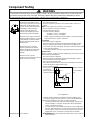
Operation test
If voltage, capacitor, overload, and motor winding tests do not show cause for
failure, perform the following test:
1. Disconnect power to refrigerator.
2. Discharge capacitor by shorting capacitor terminals through a resistor.
3. Remove leads from compressor terminals.
4. Wire a test cord to power switch.
5. Place time delayed fuse with UL rating equal to amp rating of motor in test
cord socket. (Refer to Technical Data Sheet)
6. Remove overload and relay.
7. Connect start, common and run leads of test cord on appropriate terminals
of compressor.
8. Attach capacitor leads of test cord together. If capacitor is used, attach
capacitor lead to a known good capacitor of same capacity.
Test configuration
9. Plug test cord into multimeter to determine start and run wattage and to
check for low voltage, which can also be a source of trouble indications.
10. With power to multimeter, press start cord switch and release.
• If compressor motor starts and draws normal wattage, compressor is
okay and trouble is in capacitor, relay/overload, freezer temperature
control, or elsewhere in system.
• If compressor does not start when direct wired, recover refrigerant at
high side. After refrigerant is recovered, repeat compressor direct wire
test. If compressor runs after recovery but would not run when direct
wired before recover, a restriction in sealed system is indicated.
• If compressor does not run when wired direct after recovery, replace
faulty compressor.
C
R
S
Fuses
Capacitor
Compressor
Switch
To AC supply

Component Testing
!WARNING
To avoid risk of electrical shock, personal injury, or death, disconnect electrical power source to unit, unless test
procedures require power to be connected. Discharge capacitor through a resistor before attempting to service.
Ensure all ground wires are connected before certifying unit as repaired and/or operational.
8 16022323 Rev. 0 ©2003 Maytag Appliances Company

Component Testing
!WARNING
To avoid risk of electrical shock, personal injury, or death, disconnect electrical power source to unit, unless test
procedures require power to be connected. Discharge capacitor through a resistor before attempting to service.
Ensure all ground wires are connected before certifying unit as repaired and/or operational.
©2003 Maytag Appliances Company 16022323 Rev. 0 9
Component Description Test Procedures
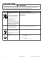
Capacitor
Run capacitor connects to relay
terminal 3 and N side of line.
Some compressors do not require a run
capacitor; refer to the Technical Data
Sheet for the unit being serviced.
1. Disconnect power to refrigerator.
2. Remove capacitor cover and disconnect capacitor wires.
3. Discharge capacitor by shorting across terminals with a resistor for 1 minute.
4. Check resistance across capacitor terminals with ohmmeter set on “X1K”
scale.
• Good—needle swings to 0 ohms and slowly moves back to infinity.
• Open—needle does not move. Replace capacitor.
• Shorted—needle moves to 0 and stays. Replace capacitor.
• High resistance leak—needle jumps toward 0 and then moves back to
constant high resistance (not infinity).
Condenser
Condenser is a tube and fin construction
located in machine compartment.
Condenser is on high pressure
discharge side of compressor.
Condenser function is to transfer heat
absorbed by refrigerant to ambient.
Higher pressure gas is routed to
condenser where, as gas temperature
is reduced, gas condenses into a high
pressure liquid state. Heat transfer takes
place because discharged gas is at a
higher temperature than air that is
passing over condenser. It is very
important that adequate air flow over
condenser is maintained.
Condenser is air cooled by condenser
fan motor. If efficiency of heat transfer
from condenser to surrounding air is
impaired, condensing temperature
becomes higher. High liquid temperature
means liquid will not remove as much
heat during boiling in evaporator as
under normal conditions. This would be
indicated by high than normal head
pressures, long run time, and high
wattage. Remove any lint or other
accumulation, that would restrict normal
air movement through condenser.
From condenser the refrigerant flows
into the drier to evaporator and into
compressor through suction line.
Leaks in condenser can usually be detected by using an electronic leak
detector or soap solution. Look for signs of compressor oil when checking for
leaks. A certain amount of compressor oil is circulated with refrigerant.
Leaks in post condenser loop are rare because loop is a one-piece copper
tube.
For minute leaks:
1. Separate condenser from rest of refrigeration system and pressurize
condenser up to a maximum of 235 PSI with a refrigerant and dry nitrogen
combination.
2. Recheck for leaks.
WARNING
!
To avoid severe personal injury or death from sudden eruption of high
pressures gases, observe the following:
Protect against a sudden eruption if high pressures are required for
leak checking.
Do not use high pressure compressed gases in refrigeration systems
without a reliable pressure regulator and pressure relief valve in the
lines.
WARNING!
To avoid electrical shock which can cause severe personal injury or
death, discharge capacitor through a resistor before handling.

Component Testing
!WARNING
To avoid risk of electrical shock, personal injury, or death, disconnect electrical power source to unit, unless test
procedures require power to be connected. Discharge capacitor through a resistor before attempting to service.
Ensure all ground wires are connected before certifying unit as repaired and/or operational.
10 16022323 Rev. 0 ©2003 Maytag Appliances Company
Component Description Test Procedures
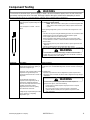
PTC Relay
When voltage is connected and relay is
cool, current passes through relay to
start winding.
After a short time, current heats the
resistor in relay and resistance will rise
blocking current flow through relay.
Start winding remains in the circuit
through run capacitor.
Solid state relay plugs directly on
compressor start and run terminals. Relay
terminals 2 and 3 are connected within
relay. Run capacitor is connected to relay
terminal 3. L2 side of 120 VAC power is
connected to relay terminal 2.
1. Disconnect power to the refrigerator.
2. Remove relay cover and disconnect leads.
3. Check resistance across terminals 2 and 3 with an ohmmeter:
Normal = 3 to 12 ohms
Shorted = 0 ohms
Open = infinite ohms
(SSAC) Electronic
control
Electronic control that uses a thermistor to
sense temperature of cabinet and
rheostat to adjust temperature.
1. Check resistance of thermistor before replacing Electronic control.
2. If resistance of thermistor is good replace Electronic control
Condenser motor
Condenser fan moves cooling air across
condenser coil and compressor body.
Condenser fan motor is in parallel circuit
with compressor.
Check resistance across coil.
Cabinet light
switch
Single pole, single throw switch
completes circuit for light when door is
open.
Check resistant across terminals.
Switch arm depressed
“NO” terminals Open
Switch arm up
“NO” terminals Closed

Component Testing
!WARNING
To avoid risk of electrical shock, personal injury, or death, disconnect electrical power source to unit, unless test
procedures require power to be connected. Discharge capacitor through a resistor before attempting to service.
Ensure all ground wires are connected before certifying unit as repaired and/or operational.
©2003 Maytag Appliances Company 16022323 Rev. 0 11
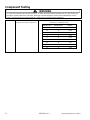
Drier
Drier is placed at post condenser loop
outlet and passes liquefied refrigerant to
capillary.
Desiccant (20) 8 x 12 4AXH - 7 M>S> -
Grams
Drier must be changed every time the system is opened for testing
or compressor replacement.
NOTE: Drier used in R12 sealed system is not interchangeable with
drier used in R134a sealed system. Always replace drier in R134a
system.
Before opening refrigeration system, recover HFC134a refrigerant for safe
disposal.
1. Cut drier out of system using the following procedure. Do not unbraze drier.
2. Applying heat to remove drier will drive moisture into the system.
3. Score capillary tube close to drier and break.
4. Reform inlet tube to drier allowing enough space for large tube cutter.
5. Cut circumference of drier 1 ¼" below condenser inlet tube joint to drier.
6. Remove drier.
7. Apply heat trap paste on post condenser tubes to protect grommets from
high heat.
8. Unbraze remaining part of drier. Remove drier from system.
9. Discard drier in safe place. Do not leave drier with customer. If refrigerator
is under warranty, old drier must accompany warranty claim.
Component Description Test Procedures
Evaporator Inner volume of evaporator allows liquid
refrigerant discharged from capillary to
expand into refrigerant gas.
Expansion cools evaporator tube and fin
temperature to approximately -20°F
transferring heat from freezer section to
refrigerant.
Passing through suction line to
compressor, the refrigerant picks up
superheat (a relationship between
pressure and temperature that assures
complete vaporization of liquid
refrigerant) as the result of capillary
tube soldered to suction line.
Refrigerant gas is pulled through suction
line by compressor, completing
refrigeration cycle.
Test for leaks in evaporator with electronic leak detector or with soap solution.
Compressor oil is circulated with refrigerant; check for oil when checking for
leaks.
For minute leaks:
1. Separate evaporator from rest of refrigeration system and pressurize
evaporator up to a maximum of 140 PSI with a refrigerant and dry nitrogen
combination.
2. Recheck for leaks.
WARNING!
To avoid death or severe personal injury, cut drier at correct location.
Cutting drier at incorrect location will allow desiccant beads to scatter. If
spilled, completely clean area of beads.
WARNING!
To avoid severe personal injury or death from sudden erruption of
high pressurres gases, observe the following:
•Protect against a sudden eruption if high pressures are required
for leak checking.
•Do not use high pressure compressed gases in refrigeration
systems without a reliable pressure regulator and pressure relief
valve in the lines.

Component Testing
!WARNING
To avoid risk of electrical shock, personal injury, or death, disconnect electrical power source to unit, unless test
procedures require power to be connected. Discharge capacitor through a resistor before attempting to service.
Ensure all ground wires are connected before certifying unit as repaired and/or operational.
12 16022323 Rev. 0 ©2003 Maytag Appliances Company
Thermistor Temperature sensing bulb changes
resistance with change of temperature. Check resistance vs. temperature. See chart:
Resistance vs. Temperature Chart
TEMPERATURE C
TEMPERATURE F
RESISTANCE
(KOHMS)
-15
5
11.350
-10
14
8.918
-5
23
6.700
0
32
5.630
5
41
4.520
10
50
3.652
15
59
2.970
20
68
2.430
25
77
2.000

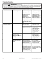
Troubleshooting To avoid risk electrical shock, personal injury, or death,
always disconnect electrical power source to the freezer
before attempting to service, unless test procedures require
power to be connected. When removing any wiring from terminals they must be replaced on the same terminals.
Ensure all ground wires are connected before certifying unit as repaired and/or operational.
WARNING
!
©2003 Maytag Appliances Company 16022323 Rev. 0 9
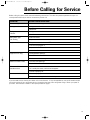
PROBLEM CHECK POSSIBLE CAUSE REMEDY
Interior too cold or
contents freezing. Thermostat setting Thermostat set to too cold
of a setting for ambient
conditions.
Adjust thermostat warmer
setting (lower number on
knob).
The evaporator for the
presence of a uniform
frost pattern. Is the frost
confined to left wing and
the left side of the back?
Note: Compressor should
be operating for least 5
minutes with door open to
perform this check.
Refrigerant leak or low
refrigerant charge in the
sealed system.
Refrigerant volume in
evaporator is not sufficient
to cool the region of the
plate where the
evaporator plate sensing
thermostat’s thermo bulb
mounts. Therefore the
control thermostat never
reaches its cutout
temperature and the
compressor operates
100% of the time. The
remaining evaporator
volume is sufficient to cool
the air temperature below
freezing.
Locate and correct cause
of refrigerant leak.
Replace drier, evacuate
and recharge sealed
refrigerant system with the
proper amount of charge
as listed on the unit’s data
plate.
Thermostat (compressor
control) thermo bulb
mounting or routing.
Mounting location
incorrect. Model should be
on the right wing of the
evaporator plate. All other
models mount at the rear
top center of the
evaporator.
Relocate thermo bulb to
proper location.
Thermostat sensing tube
(capillary tube) resting on
or above compressor
dome in mechanical
compartment causing
false sensing.
Reroute sensing tube
clear of compressor dome
area.
Thermostat thermo bulb
mounting bracket not
secure, causing false
sensing.
Securely tighten thermo
bulb mounting bracket.
Insufficient thermo bulb
contact area on
evaporator U-shaped loop
with 3-inch long legs
required. Bracket should
be located at mid point of
each 3-inch leg. Both legs
secured under bracket.
Adjust thermo bulb contact
area to achieve sufficient
contact. A U-shaped loop
with 3-inch long legs is
required. The mounting
bracket should be located
at the mid-point of each 3-
inch leg. Both legs
secured under bracket.

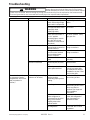
Troubleshooting To avoid risk electrical shock, personal injury, or death,
always disconnect electrical power source to the freezer
before attempting to service, unless test procedures require
power to be connected. When removing any wiring from terminals they must be replaced on the same terminals.
Ensure all ground wires are connected before certifying unit as repaired and/or operational.
WARNING
!
10 16022323 Rev. 0 ©2003 Maytag Appliances Company
PROBLEM CHECK POSSIBLE CAUSE REMEDY
Placement of glass
shelves in cabinet interior. Do not space the glass
shelf out away from the
molded in liner shelf
supports on the back of
the cabinet interior the
cold air from the
evaporator can be
“trapped” above the shelf
resulting in the area
above the shelf becoming
too cold and below too
warm (This applies to
models with glass shelves
only).
Properly place the glass
shelves in the unit. White
rubber “shelf bumper”
must be placed so as to
create a air space gap
between the rear edge of
the glass shelf and the
molded shelf supports on
the back of the cabinet
interior.
Interior too warm
(compressor operates). Thermostat Thermostat set to too low
(warm) of a setting. Adjust thermostat to a
colder setting (higher
number on knob).
Thermostat failed, cutting
compressor off too soon. Replace thermostat. Leak
check the sealed.
Refrigeration system.
Locate and correct the
source of the leak.
Replace the drier and
recharge to proper
amount.
The evaporator for the
presence of a frost
pattern. If frost not present
with compressor
operating.
Refrigerant leak. Leak check the sealed
refrigeration system.
Locate and correct the
source of the leak.
Replace the drier and
recharge to proper
amount.
High and low side
pressures in the sealed
system.
Compressor valve failure,
preventing compressor
from developing required
refrigerant pressures for
system operation.
Replace compressor and
drier, evacuate and
recharge with refrigerant
to the proper amount.
Restriction in the sealed
refrigerant system causing
high compressor
discharge pressures and
low pressures or vacuum
conditions on the suction
side. Pressure does not
equalize quickly when the
compressor is turned off.
Locate the restriction and
correct the cause.
Evacuate, replace drier
and recharge the sealed
refrigeration system to the
proper level.

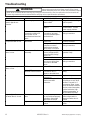
Troubleshooting To avoid risk electrical shock, personal injury, or death,
always disconnect electrical power source to the freezer
before attempting to service, unless test procedures require
power to be connected. When removing any wiring from terminals they must be replaced on the same terminals.
Ensure all ground wires are connected before certifying unit as repaired and/or operational.
WARNING
!
©2003 Maytag Appliances Company 16022323 Rev. 0 11
PROBLEM CHECK POSSIBLE CAUSE REMEDY
Failed light activation
switch not turning off light
when switch is depressed.
Replace light activation
switch.
Wiring connection to or
from light activation switch
improperly wired
bypassing switch.
Correct improper wiring
connection.
Door light activation
switch over-ride switch in
the “on” position
permitting light to remain
“on” with door closed.
(Present on some but not
all models).
Place over-ride switch in
the “door” position. Verify
light goes out.
Condenser fan operation. Condenser fan blade
jammed against shroud or
otherwise bound.
Correct loose or incorrect
wiring connections.
Wiring connection to and
from fan motor, terminal
block and thermostat
loose or incorrect
Correct loose or incorrect
wiring connections.
Condenser fan motor
failed Replace condenser fan
assembly.
Condenser airflow
blocked or restricted. Condenser air flow
blocked by dirt, lint, trash,
etc.
Clean condenser to
restore airflow.
Airflow in or out of toe
space grille restricted. Clear restriction to airflow
through toe space grille.
No obstruction to air flow
permitted in an area 3 feet
out from the grille.
Excessive frost build-up
on evaporator (interior
temperatures are normal
and frost pattern is
uniform).
Cabinet for proper sealing
(absence of air leaks). Exterior door of unit not
hanging straight
preventing proper gasket
sealing.
Install door shim kit to
correct hang of door.
Door hinges bent Install new hinge kit to
correct hang of door. Door
shims may also be
required. See hinge and
shim installation
instructions.
Air leaks at locations
where refrigerant or
thermostat line electrical
wiring or thermostat
capillary tubes enter
cabinet interior.
Seal around these entry
points with refrigeration
putty (permagum) to
eliminate air leaks.
Door gasket torn or has
lost magnetism. Replace gasket if stiff, torn
or has stiff, torn or weak
magnetism.

Troubleshooting To avoid risk electrical shock, personal injury, or death,
always disconnect electrical power source to the freezer
before attempting to service, unless test procedures require
power to be connected. When removing any wiring from terminals they must be replaced on the same terminals.
Ensure all ground wires are connected before certifying unit as repaired and/or operational.
WARNING
!
12 16022323 Rev. 0 ©2003 Maytag Appliances Company
PROBLEM CHECK POSSIBLE CAUSE REMEDY
Compressor, fan and
interior light do not
function.
Power supply Unit not plugged into
power outlet. Plug unit into power Plug
unit into power.
Fuse or circuit breaker
tripped. Replace fuse. Reset
circuit breaker. Correct
power supply problem.
Power cord and wiring
connections within unit
from power cord to
thermostat and terminal
block.
Loose or incorrect wiring
connections at power
cord, thermostat input or
terminal block.
Correct loose or incorrect
wiring connections.
Interior light functions but
compressor will not run. Compressor control
thermostat. Compressor control
thermostat. Replace compressor
control thermostat.
Wiring connections from
compressor control
thermostat to terminal
block loose or incorrect.
Correct loose or incorrect
wiring connections.
Compressor runs; fan
does not run. Fan motor and blade
assembly. Fan blade jammed by
shroud, refrigerant line,
mount bracket, foreign
object, etc.
Free fan blade so fan
operates freely.
Fan motor failed Replace fan motor.
Connection loose or
incorrect on wiring from
fan motor to terminal
block.
Correct loose or incorrect
wiring connections.
Fan runs, but compressor
does not run. PTC starter Failed PTC starter. Replace PTC starter.
Wiring PTC start to
terminal start to terminal. Loose or incorrect wiring
connections at PTC
starter to terminal block.
Correct loose or incorrect
wiring.
Compressor Failed motor in
compressor Replace compressor
Compressor cycled off on
thermal overload
protection.
Unplug unit. Allow
compressor to cool 30-45
minutes. Plug unit in. If
compressor starts, locate
cause of thermal overload.
May be power interruption,
system restriction, high
ambient temperature, or
fan/condenser blocked.
Interior light will not turn
off when door is closed. Striker plate on bottom of
door. Striker plate not present
or not positioned properly
to depress light switch
when door is closed.
Replace or install striker
plate so light switch is
depressed when door is
closed.
Light activation switch. Failed light activation
switch. Replace light activation
switch.

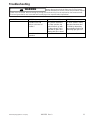
Troubleshooting To avoid risk electrical shock, personal injury, or death,
always disconnect electrical power source to the freezer
before attempting to service, unless test procedures require
power to be connected. When removing any wiring from terminals they must be replaced on the same terminals.
Ensure all ground wires are connected before certifying unit as repaired and/or operational.
WARNING
!
©2003 Maytag Appliances Company 16022323 Rev. 0 13
PROBLEM CHECK POSSIBLE CAUSE REMEDY
Position of door light
activation over-ride
switch. Is it in the “on”
position?
If over-ride switch is in the
“on” position instead of
the “door” position, the
light will remain on with
the door closed. This is
intended for glass door
viewing with door closed.
Place over-ride switch in
the “door” position. Verify
light goes out when door
is closed by depressing
light activation switch and
confirming light goes out.
Over-ride switch
operation. Failed over-ride switch. Replace over-ride switch

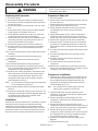
Disassembly Procedures To avoid risk of electrical shock, personal injury or
death; disconnect power to unit before following any
disassembly procedures.
WARNING
!
14 16022323 Rev. 0 ©2003 Maytag Appliances Company
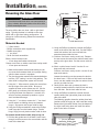
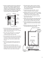
Replacing the Evaporator:
1. Disconnect power,
2. Remove the screws securing the evaporator plate.
3. Remove the machine compartment and rear panel at
the rear of the unit.
4. Remove the putty from the opening in the rear of the
liner.
5. Remove the three screws that secure the baseplate
to the cabinet on the bottom of the unit.
6. Gently slide the mechanical out the rear of the unit
just enough to gain access to the assembly.
7. Install the access valve and recover refrigerant. After
recovering, be sure to cap off the access valve to
prevent contamination of the system.
8. Remove the cap from the rear of the compressor.
9. Disconnect the PTC starter relay at the compressor
by pulling off. You will not need to disconnect the
three wires.
10.Un-braze and remove the capillary tube from the drier
assembly.
11.Un-braze and remove the drier assembly at the
condenser.
12.Un-braze and remove the suction line at the
compressor.
13.Un-braze the discharge line at the compressor.
14.Remove the compressor by removing the two lock-
nuts on the mounting plate of the compressor. Lift the
compressor off of the carriage bolts.
15.Install the four rubber grommets in the bottom of the
new compressor and install the two sleeves where
the carriage bolts will be located. Mount the new
compressor and install the two washers and lock-
nuts and tighten to 45 in-lb.
Note: Do not remove the rubber plugs at the tube stubs
on the compressor at this time.
16.Remove the insulation tube on the evaporator tubing
harness.
17.Remove the evaporator from the front of the unit. The
evaporator will need to be tilted 90 degrees down and
the tubing harness with the accumulator will fit
through the opening in the liner.
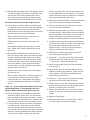
Installation:
Reverse the removal instructions for installation. Remove
the plugs from the compressor right before brazing.
Make certain that the suction line and tubing harness
insulation tube are installed and sealed. Also, check the
thermistor to make sure it has full contact and is secure.
Be sure to check for leaks and evacuate to 50 microns.
Compressor Removal:
1. Disconnect power.
2. Remove the machine compartment and rear panel at
the rear of the unit.
3. Remove the three screws that secure the baseplate
to the cabinet on the bottom of the unit.
4. Gently slide the mechanical out the rear of the unit
just enough to gain access to the compressor
assembly.
5. Install sealed system access valve(s) and recover
refrigerant. After recovering, be sure to cap off the
access valve to prevent contamination of the system.
6. Remove the cap from the rear of the compressor.
7. Disconnect the PTC starter relay at the compressor
by pulling off. You will need to disconnect the three
wires from the old PTC starter and then connect the
new one.
8. Un-braze and remove the capillary tube from the drier
assembly.
9. Un-braze discharge tube from compressor at the
compressor.
10.Un-braze and remove the drier assembly from
condenser out tube.
11.Un-braze and remove the suction line at the
compressor.
12.Remove the compressor by removing the two lock-
nuts on the mounting plate of the compressor. Lift the
compressor off of the carriage bolts.
Compressor Installation:
1. Install the four rubber grommets in the bottom of the
new compressor and install the two sleeves where
the carriage bolts will be located. Mount the new
compressor and install the two washers and lock-
nuts and tighten to 45 in-lb.
Note: Do not remove the rubber plugs at the tube
stubs on the compressor at this time.
2. Install and braze the new drier assembly to the
condenser. Then install and braze the capillary tube
and the discharge out.
3. Remove the plug for the discharge line at the
compressor. Install and braze the discharge line to
the compressor.
4. Remove the plug for the process tube on the
compressor. Install and braze in the process tube. Be
sure to cap off the end to prevent any contamination.
5. Remove the plug for the suction line on the
compressor. Install and braze in the suction line from
the evaporator. Be sure to also reinstall the suction
line and tubing harness insulation tubes.
6. Reinstall PTC starter and wire according to wire
diagram.
7. Reinstall compressor cap.

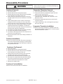
Disassembly Procedures To avoid risk of electrical shock, personal injury or
death; disconnect power to unit before following any
disassembly procedures.
WARNING
!
©2003 Maytag Appliances Company 16022323 Rev. 0 15
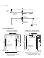
Condenser Removal:
1. Disconnect power.
2. Remove the machine compartment panel.
3. Remove the three screws that secure the baseplate
to the cabinet on the bottom of the unit.
4. Gently slide the mechanical out the rear of the unit
enough to gain access to the condenser coil and fan
shroud.
5. Install sealed system access valve(s) and recover
refrigerant. After recovering, be sure to cap off the
access valve to prevent contamination of the system.
6. Remove the fan by removing the screws on the fan
mounting bracket at the baseplate. The fan wire
leads can be left connected. Set the fan assembly to
the side of the machine compartment.
7. Un-braze the capillary tube from the drier assembly.
8. Un-braze and remove the drier assembly.
9. Un-braze the discharge line from the compressor at
the top of the condenser coil.
10. Remove with electric drill rivets holding condenser to
baseplate.
Condenser Installation:
Reverse the removal procedure. Be sure to evacuate to
50 microns before weight charging. If contamination
was found or determined, the evaporator should also
be replaced at this time.
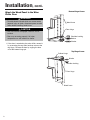
Condenser Fan Removal:
1. Disconnect power.
2. Remove the machine compartment panel.
3. Remove the three screws that secure the baseplate
to the cabinet on the bottom of the unit.
4. Gently slide the mechanical out the rear of the unit
enough to gain access to the condenser fan.
5. Remove the screws that secure the condenser fan.
6. Disconnect the neutral white wire lead (black ribbed
wire) at the terminal block and the hot wire lead
(black smooth wire) at the electronic control.
7. Remove the condenser fan.
Condenser Fan Installation:
Reverse the removal procedure for installation.
Evaporator Thermistor Removal:
1. Disconnect power, water line, and drain line.
2. Remove the machine compartment panel and rear
panel from the rear of the unit.
3. Disconnect the red and black wires to the
“EVAPORATOR THERMISTOR” terminals on the
electronic control.
4. Remove the evaporator thermistor by removing the
screw securing it.
5. Feed the thermistor’s wire out through the opening in
the rear of the unit.
Evaporator Thermistor Installation:
Reverse the removal procedure for installation. Be sure
to thoroughly tighten the thermistor’s screw for proper
bracket to thermistor contact.

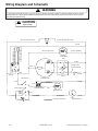
To avoid risk of electrical shock, personal injury, or death, disconnect power to freezer before servicing, unless
testing requires it. Wires removed during disassembly must be replaced on proper terminals to insure correct
grounding and polarization.
CAUTION
!High Voltage
!WARNING
Wiring Diagram and Schematic
16 16022323 Rev. 0 ©2003 Maytag Appliances Company
WHITE
OPTIONAL FEATURE
FAN
CONDENSER
RELAY
P.T.C.
RED
RED
LIGHT SWITCH
BLACK SWITCH
ON/OFF BLUE
BLACK
RED
BLUE
TRANSFORMER INTERIOR FAN
BLACK
4
8
2
57
ON
3
1
21
64
FAN SWITCH
RED
RED
THERMISTOR (GREY
(BLACK, NONPOLARIZED)
POTENTIOMETER
SLEEVE, NONPOLARIZED)
COMPRESSOR
OV'LD
8C
11
R
S
5
BLACK (SMOOTH)
5
136
WHITE
41006543 REV. E
WHITE
LIGHT
WHITE
YELLOW STRIPE
CAP.
3
WHITE WITH
BLACK (RIBBED)
2WHITE
BLACK, RIBBED (NEUTRAL)
BLACK, SMOOTH (HOT)
DIMMER SWITCH
Page is loading ...
Page is loading ...
Page is loading ...
Page is loading ...
Page is loading ...
Page is loading ...
Page is loading ...
Page is loading ...
Page is loading ...
Page is loading ...
Page is loading ...
Page is loading ...
Page is loading ...
Page is loading ...
Page is loading ...
Page is loading ...
Page is loading ...
Page is loading ...
Page is loading ...
Page is loading ...
Page is loading ...
Page is loading ...
Page is loading ...
Page is loading ...
Page is loading ...
Page is loading ...
Page is loading ...
Page is loading ...
Page is loading ...
Page is loading ...
Page is loading ...
Page is loading ...
-
 1
1
-
 2
2
-
 3
3
-
 4
4
-
 5
5
-
 6
6
-
 7
7
-
 8
8
-
 9
9
-
 10
10
-
 11
11
-
 12
12
-
 13
13
-
 14
14
-
 15
15
-
 16
16
-
 17
17
-
 18
18
-
 19
19
-
 20
20
-
 21
21
-
 22
22
-
 23
23
-
 24
24
-
 25
25
-
 26
26
-
 27
27
-
 28
28
-
 29
29
-
 30
30
-
 31
31
-
 32
32
-
 33
33
-
 34
34
-
 35
35
-
 36
36
-
 37
37
-
 38
38
-
 39
39
-
 40
40
-
 41
41
-
 42
42
-
 43
43
-
 44
44
-
 45
45
-
 46
46
-
 47
47
-
 48
48
-
 49
49
-
 50
50
-
 51
51
-
 52
52


Jenn-Air JUC2450ACX User manual
- Category
- Wine coolers
- Type
- User manual
- This manual is also suitable for
Ask a question and I''ll find the answer in the document
Finding information in a document is now easier with AI
Related papers
Other documents
-
BLACK DECKER BCRK32 Operating instructions
-
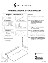 SMITH SYSTEM 179802 Assembly Instructions
-
Maytag JCD2295KE Series Owner's manual
-
Maytag MFI2067AE Series Owner's manual
-
Maytag ATB2136AR series Operating instructions
-
-
Emerson CR0016W Owner's manual
-
-
Grisham 90009 Installation guide
-
Kogan KASTDGLSBLA User guide
