Page is loading ...

Figure 2
Datacom
Wiring Jacks
and Connectors
1 Do not use this or any electrical product
near water (unless specifically
designated for use in wet locations).
2 To avoid electrical shock or equipment
damage, never push foreign objects into
the openings of this device.
3 Do not install telephone wiring during
thunder and lightning storms.
4 Disconnect the telephone line at the
network interface (where telephone wiring
enters your home) before touching
uninsulated telephone wire or terminals.
5 Fill all unused wall plate outlets with
blanks to prevent access to energized
wires or parts.
6 Use caution when handling or installing
any telephone, computer, video, or
electrical devices.
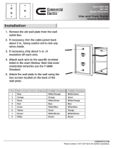
1 Pull your coaxial cable through the
opening in the wall plate.
2 Mount the wall plate to the electrical box
or low-voltage bracket.
3 Following the instructions provided by
the manufacturer, attach an appropriate
connector to your coaxial cable.
4 Attach the MNM2 F Connector (see
Figure 1):
• Place the threads of the coaxial cable
connector against the threaded barrel
on the back of the MNM2.
• Hold the coaxial cable connector
stationary and rotate the MNM2
clockwise until it is fully seated.
5 Insert the MNM2 into the wall plate (see
Figure 2). Apply light pressure until it
snaps into place.
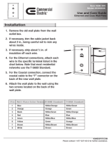
1 Feed the speaker cable through the
opening in the wall plate.
2 Mount the wall plate to the electrical box
or low-voltage bracket.
3 Strip about 3/8" of insulation from each
conductor.
Back the hex nut on the back of the
binding post completely out by turning
counterclockwise.
4 Insert the conductor directly through the
hole in the rear shaft of the binding post.
5 Tighten the hex nut on the back of the
binding post by turning the nut
clockwise. Make sure the nut is
sufficiently tight to ensure a good
connection.
6 Insert the binding post into the wall plate
(see Figure 1). Apply light pressure until
it snaps into place.
7 If necessary, repeat steps 1-6 for the
second binding post.
Making Connections to the Front of the
Binding Post
1 If you are using a male banana
connector, plug the connector directly into
the opening on the front side of the
binding post.
2 If you are making a wire connection:
• Strip off approximately 3/8" of
insulation using a cable-stripping tool.
• Back out the nut on the front of the
binding post by turning it
counterclockwise.
• Insert the conductor through the hole
in the binding post shaft.
• Tighten the nut by turning it clockwise.
Make sure the nut is sufficiently tight to
ensure a good connection.
TIPS – Be Careful to Ensure Consistent
Polarity – and to Avoid Speaker Wire
Short Circuits.
Speaker wire and connections are
commonly designated positive and
negative. This is called polarity. When
installing speaker wiring and making
connections, ensure that positive and
negative connections are not reversed. If a
speaker is connected with polarity reversed
compared to other speakers, it will operate
out of phase with other speakers and
cause reduced audio performance.
Speaker wire short circuits can damage an
amplifier or receiver. Be careful whenever
making speaker wire connections to ensure
that positive and negative speaker
conductors cannot contact one another at
any point.
Santa Clara, CA 95050
800.879.8585
™
MNM4: Binding Post Installation
MNM2: F Connector Installation
Safety Tips
Figure 1
Figure 1

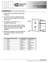
1 Feed the 4-pair, unshielded twisted-pair
cable through the opening in the wall
plate.
2 Mount the wall plate to the electrical box
or low-voltage bracket.
3 Strip off approximately 2" of cable jacket
with an appropriate cable stripping tool
such as Pass & Semour Cat.# PSSTV.
4 Separate the cable pairs by color
(Blue/Blue-White, Orange/Orange-
White, Green/Green-White, and
Brown/Brown-White).
5
IMPORTANT: Each wire pair must be
connected (terminated) to the correct
insulation-displacement contacts (see
Figure 1). Match the applicable color
code shown on the jack (either 568A or
568B, see Note 1).
6 Place each wire pair into the insulation-
displacement contacts on the back of
the jack.
7 Set the face of the jack module into the
track of the wall plate, frame (if using 2-
piece decorator plates), or against any
other stable surface (see Note 2).
8a If using a 110-type punchdown tool (for
example, Pass & Semour Cat.#
PSIHTV), terminate the Blue cable pair:
• Place the tool over each individual
wire. The cutting edge of the blade
must face the outside of the
insulation-displacement contacts (see
Figure 2).
• Punch each wire into place on the
contacts.
• Repeat for Orange, Green, and
Brown cable pairs.
8b Alternative Termination (For USOC/Cat
5e): Proceed through Step 6. Place
stuffer cap over contacts. Using
channel-type pliers, firmly seat cap onto
contact block. Using diagonal cutters,
trim excess wire. Proceed with Step 10
(see Figure 3).
9 When the terminations are completed,
push the provided stuffer caps over the
insulation-displacement contacts.
10 Turn the jack over and insert it into the
wall plate (see Figure 4). Apply light
pressure until it snaps into place.
Note 1: For residential applications, follow
the 568A or “A” color-code shown on the
back of the jack.
Note 2: When terminating a jack module in
either 4-, or 6-outlet wall plates, we
recommend that a jack be installed in
the adjacent corner to provide support
during the punchdown operation.
TIP – For Best Performance, Handle
Network Wiring Cable Carefully!
In twisted-pair network cabling (such as
category rated cable), the wire pairs are
twisted together because this helps prevent
a type of interference called near-end
crosstalk (NEXT). Anything that disrupts the
twisting can reduce network performance.
When installing network cable, don’t bend it
sharply (a bending radius of 1 inch or more
is recommended). Don’t use too much
force to pull cable (no more than 25
pounds of pulling force). Don’t strip more
jacket than is necessary to make
connections (terminations) — and don’t
untwist cable pairs more than 1/2" from the
termination point.
MNM5: Cat 5 or 5e Jack Installation
Figure 2
Figure 1
Figure 3
Figure 4
Warranty Information
Watt Stopper/Legrand warranties its products to be
free of defects in materials and workmanship for a
period of five years. There are no obligations or
liabilities on the part of Watt Stopper/Legrand for
consequential damages arising out of or in
connection with the use or performance of this
product or other indirect damages with respect to
loss of property, revenue, or profit, or cost of
removal, installation or reinstallation.
2800 De La Cruz Boulevard
Santa Clara CA 95050
Technical Support: 800.879.8585
www.wattstopper.com
04369r2 3/2005
ORDERING INFORMATION
MNM2-G Cable Jack F Connector, pack-
MNM2-W age of 5
MNM2-A
MNM4-G Speaker Post Jacks, color-
MNM4-W coded for left and right”
MNM4-A
MNM5-G Data/Phone CAT 5e Jacks,
MNM5-W package of 5
MNM5-A
MNA4-G Datacom Adaptor,
MNA4-W fits Miro MP series
MNA4-A Cover Plates,
accomodates four
Miro MNM
Datacom wiring
jacks
-G designates Miro Charcoal Gray
-W designates Miro Warm White
-A designates Light Almond
/