
68-2224-01 Rev. D
09 20
SF 3C LP and SF 3CT LP
User Guide
Speakers
SoundField XD 3" Full-Range Ceiling Speakers
with 4" Low Profile Composite Back Can

Copyright
© 2016-2020 Extron. All rights reserved. www.extron.com
All trademarks mentioned are the property of their respective owners..
Trademarks
All trademarks mentioned in this guide are the properties of their respective owners.
The following registered trademarks (
®
), registered service marks (
SM
), and trademarks (
TM
) are the property of RGBSystems, Inc. or Extron
(see the current list of trademarks on the Terms of Use page at www.extron.com):
Registered Trademarks
(
®
)
Extron, Cable Cubby, ControlScript, CrossPoint, DTP, eBUS, EDID Manager, EDID Minder, eLink, Flat Field, FlexOS, Glitch Free, Global
Configurator, Global Scripter, GlobalViewer, Hideaway, HyperLane, IP Intercom, IP Link, Key Minder, LinkLicense, LockIt, MediaLink,
MediaPort, NAV, NetPA, PlenumVault, PoleVault, PowerCage, PURE3, Quantum, ShareLink, Show Me, SoundField, SpeedMount,
SpeedSwitch, StudioStation, System INTEGRATOR, TeamWork, TouchLink, VideoLounge, V-Lock, VN-Matrix, VoiceLift, WallVault, WindoWall,
XPA, XTP, XTP Systems, and ZipClip
Registered Service Mark
(SM)
: S3 Service Support Solutions
Trademarks
(
™
)
AAP, AFL (Accu-RATE Frame Lock), ADSP (Advanced Digital Sync Processing), Auto-Image, AVEdge, CableCover, CDRS (Class D Ripple
Suppression), Codec Connect, DDSP (Digital Display Sync Processing), DMI (Dynamic Motion Interpolation), Driver Configurator, DSP
Configurator, DSVP (Digital Sync Validation Processing), EQIP, Everlast, FastBite, Flex55, FOX, FOXBOX, IP Intercom HelpDesk, MAAP,
MicroDigital, Opti-Torque, PendantConnect, ProDSP, QS-FPC - QuickSwitch Front Panel Controller, Room Agent, Scope-Trigger, SIS -
Simple Instruction Set, Skew-Free, SpeedNav, Triple-Action Switching, True4K, True8K, Vector™ 4K, WebShare, XTRA, and ZipCaddy

FCC Class A Notice
This equipment has been tested and found to comply with the limits for a Class A digital device, pursuant to
part15 of the FCC rules. The ClassA limits provide reasonable protection against harmful interference when
the equipment is operated in a commercial environment. This equipment generates, uses, and can radiate
radio frequency energy and, if not installed and used in accordance with the instruction manual, may cause
harmful interference to radio communications. Operation of this equipment in a residential area is likely to cause
interference; the user must correct the interference at his own expense.
NOTE: For more information on safety guidelines, regulatory compliances, EMI/EMF compatibility,
accessibility, and related topics, go to
https://www.extron.com/68-290-01 on the Extron
website.
Conventions Used in this Guide
Notifications
The following notifications are used in this guide:
WARNING: Potential risk of severe injury or death.
AVERTISSEMENT : Risque potentiel de blessure grave ou de mort.
ATTENTION:
• Risk of property damage.
• Risque de dommages matériels.
NOTE: A note draws attention to important information.
Specifications Availability
Product specifications are available on the Extron website, www.extron.com.
Extron Glossary of Terms
A glossary of terms is available at https://www.extron.com/technology/glossary.aspx.

Contents
Introduction............................................................ 1
About this Guide ................................................. 1
Overview ............................................................ 1
Features ............................................................. 1
Application Example ........................................... 3
Installation .............................................................. 4
Installation Considerations .................................. 4
Installation Configurations ................................... 4
Installing the Speaker System in a Suspended
Ceiling — Single Installer ................................... 5
Installing the Speaker System in a Suspended
Ceiling —
Division of Labor .............................................. 16
Installing the Speaker System in a Hard
Ceiling ............................................................. 30
Painting the Speaker Grille ................................ 39
Troubleshooting: Signal Test Points ................... 40
Testing Source Signal (All Configurations) ...... 40
Testing the Impedance (Loop-Through
Configuration Only) ...................................... 40
SF 3C LP and SF 3CT LP User Guide • Contents ix

SF 3C LP and SF 3CT LP User Guide • Contents x

Introduction
This section gives an overview of the Extron SF 3C LP and SF 3CT LP Full Range 3-inch
SoundField Ceiling Speakers with 4-inch Low-Profile Back Can. It also provides a list of
system features and an application diagram. Topics include:
• About this Guide
• Overview
• Features
• Application Example
About this Guide
This guide describes the SF 3C LP and SF 3CT LP speakers and provides instructions for
installing all components of the system in different types of ceilings.
NOTE: Observe all applicable building codes and local ordinances when installing the
speaker.
Overview
The SF 3C LP and SF 3CT LP meet stringent UL 2043 requirements for smoke and heat
release in plenum air spaces. The 3-inch (76 mm) full-range driver features a frequency
range of 65 Hz to 20 kHz and a conical dispersion of 165 degrees. The SF 3C LP and
SF 3CT LP feature a thin-edged bezel and a magnetically attached grille.
The SF 3C LP supports 8 ohm operation. The SF 3CT LP supports 70 V, 100 V, and 8 ohm
direct operation. The SF 3CT LP has a 6-position rotary switch for selecting the various
power taps for 70V, 100V, or 8 ohms. The two models are physically similar, with slight
variations in weight and front baffle appearance.
The Extron SoundField SF 3C LP and SF 3CT LP are full-range ceiling speakers with 4-inch
(102 mm) low profile composite back cans for use in plenum rated ceiling environments with
limited vertical clearance above the ceiling.
Features
• 3-inch (76 mm) full-range driver with a tuned port
• 4-inch (102 mm) — deep low profile composite back can for plenum environments
• Frequency range — 65 Hz to 20 kHz
• 165-degree conical dispersion
• 16 watts continuous pink noise, 32 watts continuous program
• SF 3C LP — 8 ohm direct
SF 3C LP and SF 3CT LP User Guide • Introduction 1

• SF 3CT LP — 8 ohm direct or 70/100 volt operation on a 6 position, behind-the-grille
selector
• 8 ohm direct
• 70 volt: 16, 8, 4, 2, and 1 watt selectable
• 100 volt: 16, 8, 4, and 2 watt selectable
• White grille and bezel are paintable to match the installation environment
• Separable back can and baffle supports single-trade and division-of-labor
installations
• Modular V-rail and folding C-ring kit
• Cable/conduit access plate can be oriented for side or top connections
• Opti-Torque indicator rings prevent overtightening of locking arm screws
• Three locking arms for quick ceiling installation
• Thin bezel and magnetically attached grille
• UL 2043 plenum-rated enclosure
• UL 1480 listed for safety
• Dimensional and weight savings — reduces overall storage and shipping costs
SF 3C LP and SF 3CT LP User Guide • Introduction 2

Application Example
The illustration below is one example of configuring a system using the SF 3CT LP.
100-240V X.XA MAX, 50-60Hz
XPA 1002-70V
1
2
LIMITER/PROTECT
SIGNAL
HPF
80 Hz
OFF
ATTENUATION
REMOTE
70V OUTPUTSINPUTS
0
2
4
6
8
10
12
18
14
26
∞
0
2
4
6
8
10
12
14
∞
21
1
2
G
STANDBY
CLASS 2 WIRING
1
2
HDMI HDMI3
HDMI4
21 CONFIGURABLE
100-240V ~ --A MAX
50-60 Hz
AUDIO OUTPUT
TALLY OUT
CONTACT IN
L
1 2
R
L R
Tx Rx G
321 4 +V
1 2 3 4 G
RS-232
OUT
IN
HDMI
INPUT REMOTE
Extron
XPA 1002-70V
Power Amplier
Extron
SF 3CT LP
Ceiling Speakers
Audio
Audio
Audio
Tuner
Laptop
Extron
IN1604 HD
Four Input Scaler
POWER
12V
--A MAX
G
Tx Rx RTS CTS
COM 1
G
Tx Rx
COM 2
V C G
VOL
RELAYS
1 2 C
1 2 3 4 G
DIGITAL I/O
PWR OUT = 6W
eBUS
+V +S
-S
G
LAN
IPCP PRO 250
IR/S
S G
Projector
HDMI
HDMI
Extron
IPCP Pro 250
IP Link Pro
Control Processor
eBUS
RS-232
RS-232
Extron
EBP 100
eBUS Button Panel
2-Gang
PUSH PUSH
POWER GUIDE MENU RES 480 480p 720p 1080i 1080p
DIRECTV HD
SELECT
DIRECTV
DISPLAY
VOLUME
Extron
ON OFF
LAPTOP
TUNER
MUTE
HDMI
Figure 1. Typical SF 3CT LP Application
SF 3C LP and SF 3CT LP User Guide • Introduction 2

Installation
This section provides instructions for installing the SF 3C LP and SF 3CT LP speakers.
Topics include:
• Installation Considerations
• Installation Configurations
• Installing the Speaker System in a Suspended Ceiling — Single Installer
• Installing the Speaker System in a Suspended Ceiling — Division of Labor
• Installing the Speaker System in a Hard Ceiling
• Painting the Speaker Grille
• Troubleshooting: Signal Test Points
Installation Considerations
WARNING: Potential risk of severe injury. Installation and service must be performed
by authorized personnel only.
AVERTISSEMENT : Risque potentiel de blessure grave ou de mort. L’installation
et l’entretien doivent être effectués par le personnel autorisé uniquement.
• All wiring and electrical connections must conform to all applicable building codes and
local ordinances.
• Installation in a plenum-rated environment requires plenum rated cable or conduit.
• If using secondary support cables, the installer provides the cables.
Installation Configurations
The SF 3C LP and SF 3CT LP can be configured for the following ceiling types:
• Suspended ceiling: The following sections describe speaker installation procedures for
suspended ceilings.
• Hard ceiling: For hard ceiling installations, see Installing the Speaker System in a
Hard Ceiling on page 30.
SF 3C LP and SF 3CT LP User Guide • Installation 4

Installing the Speaker System in a Suspended Ceiling — Single Installer
If a single installer is installing the speaker system, follow this procedure for the entire system:
1. Disconnect power — Power down all attached devices before proceeding.
2. Verify the space where the system will be installed — Ensure that there is sufficient
clearance above the ceiling tile for the unit to be installed.
3. Cut a hole for the speaker — Use the provided cutout template to outline the hole to
be cut in the ceiling tile as described below.
a. Remove the ceiling tile.
b. To find the center of the tile, use a tape measure to measure the space between
two opposite corners, and mark the half-way point.
c. Position the center hole of the cutout template directly over the center of the tile
that you marked in step3b.
d. Using the provided cutout template, trace a circle around the
cutout template.
e. Cut out the circle traced on the ceiling tile.
f. Replace the tile in the ceiling.
4. Attach two V-rails and one C-ring across the tile above the hole
cut in step 3, as described below.
a. Assemble two V-rail half sections so that they become one single piece:
i. Fit the tab of one end into the slot of the other end.
ii. Open the V-rail until it locks together.
iii. Repeat this procedure for the other V-rail.
Figure 2. Assembling the V-rails
SF 3C LP and SF 3CT LP User Guide • Installation 5

b. Remove a ceiling tile adjacent to the tile with the hole.
c. Place both assembled V-rails on the cut ceiling tile and position them equally on
either side of the hole. The ends of the V-rails go over the ceiling grid.
d. Position the C-ring assembly on the two V-rails so that the C-ring is centered over
the hole, as shown below.
V
-rail
C-ring
Figure 3. Positioning the C-ring assembly on the V-rails
e. Secure the C-ring to the V-rails using two screws.
5. Route the speaker wires through the ceiling tile hole.
SF 3C LP and SF 3CT LP User Guide • Installation 6

6. Configure the locking arms for thicker ceilings (optional).
Three speaker locking arms are used to secure the speaker to ceiling tiles up to
2.25 inches (57.1 mm) thick. The locking arms are equipped with removable inserts that
accommodate ceiling tiles of up to 1.5 inches (38.1 mm) in thickness. For ceiling tiles
thicker than 1.5 inches, the locking arm inserts must be removed.
To remove the inserts:
Using a screwdriver, rotate the locking arm so that the insert can be accessed.
Figure 4. Accessing the locking arm insert
SF 3C LP and SF 3CT LP User Guide • Installation 7

f. Use a small screwdriver to pry and separate the insert from the locking arm, as
shown below.
Figure 5. Prying off the locking arm insert
g. Repeat this process for the remaining two locking arms.
h. Rotate all three locking arms back into the speaker.
7. Configure the cable conduit access plate and captive screw connector.
a. If two conduits are being used, knock out the alternate knockout.
i. Place the head of the screw driver on the notch of the knockout.
ii. Tap the back of the screwdriver until the knockout pops out.
b. Loosen the two side cable conduit access plate screws and remove the plate
before wiring the speaker.
Alternate
Knockout
Cable/Conduit
Access Plate
Screws (2)
Cable
Clamp
Figure 6. Removing the Cable Conduit Access Plate
SF 3C LP and SF 3CT LP User Guide • Installation 8

c. Configure the cable conduit access plate:
When not using conduit: Route the speaker wires through the cable clamp.
When using conduit: Remove the cable clamp and install the conduit into the
plate opening. Secure the conduit to the plate with the locking nut and pull the
speaker wires from the conduit.
NOTE: The plate has an alternate hole available by removing the knockout. See
step 7a on the previous page to remove the knockout.
d. Strip 0.2 inches (5 mm) from the wire ends.
e. Attach the speaker wires to the captive screw connector depending on the
configuration, as illustrated by the following three methods.
Wiring Multiple Speakers in Parallel
When a chain of speakers is wired this way, disconnecting
one speaker does not remove power from the remaining
speakers in the chain.
Number of Wires per
Connection Point
Maximum
Wire Gauge
1 12 AWG
2 16 AWG
4 18 AWG
Wire Gauge Table
Speaker 1
Speaker 2
IN
–
–
LOOP
–
–
IN
+
+
LOOP
+
+
(Black)
(Red)
(Red)
(Red)
(Black)
(Black)
Power Amplifier
Speaker 1
Speaker 2
(Black)
(Red)
(Red)
(Black)
Power Amplifier
(Black)
(Red)
Speaker 1
(Red)
(Black)
Power Amplifier
IN
–
–
LOOP
–
–
IN
+
+
LOOP
+
+
IN
–
–
LOOP
–
–
IN
+
+
LOOP
+
+
IN
–
–
LOOP
–
–
IN
+
+
LOOP
+
+
IN
–
–
LOOP
–
–
IN
+
+
LOOP
+
+
Wiring Multiple Speakers Using Loop-through
When a chain of speakers is wired this way, disconnecting
one speaker removes power from all downstream speakers.
Wiring a Single Speaker
1
2
3
Figure 7. Attaching the Speaker Wires to the Connector
SF 3C LP and SF 3CT LP User Guide • Installation 9

ATTENTION:
• Do not tin the wire leads before installing into the connector. Tinned wires
are not as secure in the connector and could be pulled out.
• Ne pas étamer les conducteurs avant de les insérer dans le connecteur.
Les câbles étamés ne sont pas aussi bien fixés dans le connecteur et
pourraient être retirés.
• When connecting multiple speakers in 8-ohm mode, be sure that the
combined rated impedance does not equal a value less than the minimum
rated impedance of the amplifier.
• Lors de la connexion de plusieurs enceintes en mode 8ohm, assurez vous
que le niveau d’impédance combinée ne soit pas équivalent à une valeur
inférieure à l’impédance minimum de l’amplificateur.
f. Insert the captive screw plug into the four-pole receptacle of the speaker.
Using a cable clamp on the cable conduit access plate:
Figure 8. Using a Cable Clamp
SF 3C LP and SF 3CT LP User Guide • Installation 10

Using a conduit adapter on the cable conduit access plate:
Flexible Conduit Adapter
F
lexible
C
onduit A
d
d
apter
Figure 9. Using a Conduit Adapter
g. Replace the cable conduit access plate and tighten the two retaining screws.
NOTE: The cable conduit access plate can be positioned in one of two ways
depending on installer preference. Flip the plate to the desired position with
the wire openings either on the side or on the top of the speaker enclosure
before tightening the screws.
As examples:
• The side access wire opening can be useful in low profile installations.
• The top access wire opening can be more convenient to use.
OR
h. Tighten the cable clamp if it was used.
SF 3C LP and SF 3CT LP User Guide • Installation 11

8. Mounting the speaker.
a. Insert the speaker through the bottom of the hole in the ceiling tile that was cut in
step 3 on page 5 with the wires out of the way.
b. Clamp the speaker to the C-ring by using a Phillips screwdriver to tighten the three
locking arms to the C-ring.
8W
1
6W
100 V
70 V
4W
2W
4
W
2
W
1
W
8
W
8
Ω
8
Ω
1
6W
8W
16W
100 V
4W
2W
8Ω
8Ω
Figure 10. Clamping the Speaker to the C-ring
Tightening the locking arms into rigid material:
Each of the three locking arm screws use an Opti-Torque indicator ring that snaps
and separates from its plastic ring when the screw is tightened to the correct
torque. The indicator ring falls down the screwdriver shaft. When this occurs, stop
tightening the screw to avoid overtightening the locking arms to the C-ring.
8W
16W
100 V
70 V
4W
2W
4W
2W
1W
8W
8Ω
8Ω
16W
8W
16W
100 V
4W
2W
8Ω
8Ω
Figure 11. Stop Tightening when the Opti-Torque Indictor Ring Falls
ATTENTION:
• To avoid damaging the speaker, do not overtighten the three screws.
• Pour éviter d’endommager l’enceinte, ne serrez pas trop les trois vis.
SF 3C LP and SF 3CT LP User Guide • Installation 12

Tightening the locking arms into soft material:
Because fiberglass ceilings and other soft materials are not as rigid as mineral tiles
and other hard materials, the Opti-Torque indicator rings must not be used as a
tightening guide due to the risk of overtightening.
ATTENTION:
• To avoid damaging or deforming soft ceiling material, tighten the locking
arms to secure the speaker, but short of causing the speaker to deform
the flat mounting surface of the ceiling, as seen from below.
• Afin de ne pas endommager ni d’altérer un plafond souple, serrez les bras
de verrouillage pour sécuriser l’enceinte, en veillant cependant à ce que
l’unité ne cause l’altération de la surface de montage plane du plafond,
comme illustré ci-dessous.
X
9. If required, attach a secondary support line.
a. Connect a secondary support line to the support loop on the back of the speaker
enclosure, as shown here.
Anchor end to suitable
secure points within the
solid and permanent
building structure.
Figure 12. Connecting a Secondary Support Line
ATTENTION:
• Do not allow any slack in the secondary support line.
• Ne laissez pas de mou au niveau du filin de sécurité secondaire.
b. Replace the adjacent ceiling tile that was removed in step 4b on page 6.
SF 3C LP and SF 3CT LP User Guide • Installation 13

10. For the SF 3CT LP only, set the rotary tap selector switch to the appropriate setting
using a small screwdriver.
ATTENTION:
• When setting the taps for a distributed (high impedance) system, do not tap
the system above the rated power of the amplifier.
• Lors de la mise en place des capteurs pour un système distribué (haute
impédance), n’exploitez pas le système au delà du niveau d’alimentation de
l’amplificateur.
• When connecting multiple speakers in 8-ohm mode, be sure that the combined
rated impedance does not equal a value less than the minimum rated
impedance of the amplifier.
• Lors de la connexion de plusieurs enceintes en mode 8ohm, assurez vous que
le niveau d’impédance combinée ne soit pas équivalent à une valeur inférieure
à l’impédance minimum de l’amplificateur.
8
W
16
W
1
00 V
70 V
4
W
2
W
4W
2W
1W
8W
8Ω
8
Ω
16W
Adjust the Tap Selector
8W
16W
100 V
70 V
4W
2W
4W
2W
1W
8W
8Ω
8Ω
16W
Figure 13. Setting the Rotary Tap Selector Switch
SF 3C LP and SF 3CT LP User Guide • Installation 14
Page is loading ...
Page is loading ...
Page is loading ...
Page is loading ...
Page is loading ...
Page is loading ...
Page is loading ...
Page is loading ...
Page is loading ...
Page is loading ...
Page is loading ...
Page is loading ...
Page is loading ...
Page is loading ...
Page is loading ...
Page is loading ...
Page is loading ...
Page is loading ...
Page is loading ...
Page is loading ...
Page is loading ...
Page is loading ...
Page is loading ...
Page is loading ...
Page is loading ...
Page is loading ...
Page is loading ...
-
 1
1
-
 2
2
-
 3
3
-
 4
4
-
 5
5
-
 6
6
-
 7
7
-
 8
8
-
 9
9
-
 10
10
-
 11
11
-
 12
12
-
 13
13
-
 14
14
-
 15
15
-
 16
16
-
 17
17
-
 18
18
-
 19
19
-
 20
20
-
 21
21
-
 22
22
-
 23
23
-
 24
24
-
 25
25
-
 26
26
-
 27
27
-
 28
28
-
 29
29
-
 30
30
-
 31
31
-
 32
32
-
 33
33
-
 34
34
-
 35
35
-
 36
36
-
 37
37
-
 38
38
-
 39
39
-
 40
40
-
 41
41
-
 42
42
-
 43
43
-
 44
44
-
 45
45
-
 46
46
-
 47
47
Extron SF 3CT LP User manual
- Type
- User manual
- This manual is also suitable for
Ask a question and I''ll find the answer in the document
Finding information in a document is now easier with AI
in other languages
- français: Extron SF 3CT LP Manuel utilisateur
Related papers
-
Extron SF 3C LP User manual
-
Extron SF 3C LP User manual
-
Extron CS 26T Plus Template
-
Extron CS 1226T Template
-
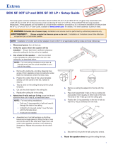 Extron electronics SF 3C LP User manual
-
Extron Cable Cubby 100 Template
-
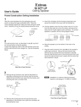 Extron electronics SI 3 User manual
-
Extron subwoofer User manual
-
Extron electronics SM 28 User manual
-
Extron SM 28 User manual
Other documents
-
NYQUIST NQ-SMS1810-SCG User manual
-
 Vinson Acoustics VAC6P Installation guide
-
RBH Sound MRB-70 Owner's manual
-
 Amperes CS606 User manual
-
Extron electronic XPA 1002 User manual
-
Bogen 150W 8 Ohm High-Performance Loudspeaker Operating instructions
-
 Amperes CS515 User manual
-
RBH Sound MTB-65 Owner's manual
-
 Extron electronics MPA 401-100V User manual
-
Extron electronic XPA 2002 User manual


