Page is loading ...

Instruction Manual
LED AREA LIGHTS
WARNING
APPLICATION NOTICE
WARNING — THE INSTALLATION MUST BE CARRIED OUT BY A QUALIFIED ELECTRICIAN.
SB150-3CCT+W | SB300-3CCT+W
• DO NOT use an electric generator to test this LED fixture
• Please abide by any related country, regional and local laws and
regulations when installing this fixture
• To avoid any electrical shock or damage, please do not install on
rainy days
• Please wear gloves to avoid injury before installing lamps
• During or aer installation, if there are situations such as smoke, fire in
the fixture, please turn o the power immediately
• This light can be used for outdoor installation.
STEP 1: Take o the waterproof cover. STEP 2: Select the Wattage or CCT by using the
slide switch.
STEP 3: Put back the waterproof cover or screw
the sensor and the rubber pad.
CAUTION
PLEASE READ INSTRUCTION BEFORE COMMENCING INSTALLATION AND RETAIN FOR FUTURE REFERENCES.
Electrical products can cause death or injury, or damage to property. If in any doubt about the installation or use of this product, consult a
competent electrician.
CCT OR WATTS SELECTED OPERATION MANUAL
WIRING DIAGRAM
www.ortechindustries.ca 604.543.6473
1.888.543.6473 13376 Comber Way,
Surrey, BC V3W 5V9
205 Summerlea Road,
Brampton, Ontario
WARNING — THE INSTALLATION MUST BE CARRIED OUT BY A QUALIFIED ELECTRICIAN.
Air Tight
70W/100W/150W
200W/240W/300W
Black / BrownACL
ACN
Green / Yellow
White / Blue
DIM-
PURRLEDIM+

Instruction Manual
LED AREA LIGHTS
OPTIONAL BRACKETS AND INSTALLATION INSTRUCTIONS
DUSK TO DAWN BEST PRACTICES
DUSK TO DAWN SENSOR INSTALLATION
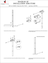
There are 5 optional brackets for this fixture.
SB150-3CCT+W | SB300-3CCT+W
This light fixture includes a Dusk to Dawn photocell sensor which controls light operation based on ambient light levels. The sensor turns the light
on in the absence of light and turns it o again when light is detected. Please note:
• The fixture must be powered on continuously for the photocell sensor to function properly
• Ensure the fixture is not obstructed by a tree or building so the sensor can properly detect available light levels
• Do not place the fixture near other light sources or reflective surfaces. If a bright light is detected in the area, the sensor will not turn the fixture on.
www.ortechindustries.ca 604.543.6473
1.888.543.6473 13376 Comber Way,
Surrey, BC V3W 5V9
205 Summerlea Road,
Brampton, Ontario
STEP 1: Remove the shorting cap. STEP 2: Insert blue Dusk to Dawn sensor into (3)
curved slots on lamp top.
STEP 3: Twist unit clockwise to lock into place.
SB-SLIP FITTER
SB-POLE-M1
SB-POLE-M2
SB-TRUNNION-1
SB-YOKE-1 / SB-YOKE-2

Instruction Manual
LED AREA LIGHTS
TYPE A: SB-SLIP FITTER
TYPE B: SB-POLE-M1
SB150-3CCT+W | SB300-3CCT+W
www.ortechindustries.ca 604.543.6473
1.888.543.6473 13376 Comber Way,
Surrey, BC V3W 5V9
205 Summerlea Road,
Brampton, Ontario
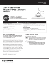
STEP 1: Disassemble the SB-SLIP FITTER
with a wrench.
STEP 4: Loosen the 4 locking bolts in
the SB-SLIP FITTER brakcet by a wrench.
STEP 2: Pass the fixture’s AC input wires through
the fixing base, then tighten screws to assemble
fixing base to fixture body.
STEP 3: Pass the fixture’s input wires through the
lamp holder and lock it.
STEP 1: Disassemble the bracket with a wrench, open the cover on
the lamp holder.
STEP 2: Pass the fixture’s iAC nput wires through fixing base, tighten
screws to assemble fixing base to fixture body.
STEP 5: Connect the ficture’s AC input wires to pole-wires with connectors,
L to L (black), N to N (white), PE to PE (green); if need to connect
dimming wires from the pole to fixture, please also use the connector to
connect “Dim+”(purple) to “Dim+”(purple), “Dim-”(pink) to “Dim-”(pink).
STEP 6: Loosen the 4 locking bolts in
the SB-SLIP FITTER brakcet by a wrench.
STEP 7: Loosen the locking bolt in the SB-SLIP FITTER by a wrench to adjust
fixture to a appropriate angle, adjustable angle range 90 then this
locking bolt.
Lamp holder
Locking bolt
Locking bolt
Fixed base
Lamp holder
Locking bolt
Fixed base

Instruction Manual
LED AREA LIGHTS
TYPE B: SB-POLE-M1
SB150-3CCT+W | SB300-3CCT+W
www.ortechindustries.ca 604.543.6473
1.888.543.6473 13376 Comber Way,
Surrey, BC V3W 5V9
205 Summerlea Road,
Brampton, Ontario
STEP 3: Pass the fixture’s input wires through the lamp holder and
lock it.
ATTENTION: When install round pole, please remove the rubber gasket.
STEP 5: When install to square/round pole, align the holes of SB-POLE-M1 bracket and pole, pass the fixing screws throughout both holes, then put
iron bar inside of pole to attach screws.
STEP 6: Pass the fixture’s AC input wires through pole, pull them out together the pole-wires for connection.
Pass the pole-wires into SB-POLE-M1 bracket, pull them out together with fixture’s AC wire from junction box, connect the fixture’s AC input wires to
pole-wires with connectors, L to L (black), N to N (white), PE to PE (green); if need to connect dimming wires from the pole to fixture, please also
use the connector to connect “Dim+”(purple) to “Dim+”(purple), “Dim -”(pink) to “Dim -”(pink).
STEP 4: Remove the screws with screwdriver, well set the installed
iron bar, remove the screws to open the junction box cover, then
pass fixture’s AC input wires through junction box as shown in step 3.
Screw
Iron bar
Rubber gasket
Iron bar
Fixing screws
Junction box
AC input wires

Instruction Manual
LED AREA LIGHTS
TYPE B: SB-POLE-M1
SB150-3CCT+W | SB300-3CCT+W
www.ortechindustries.ca 604.543.6473
1.888.543.6473 13376 Comber Way,
Surrey, BC V3W 5V9
205 Summerlea Road,
Brampton, Ontario
STEP 7: (i) Push the connected wires into the pole, close the pole’s top cover, then close the junction box cover by tightening the screws.
TYPE C: SB-POLE-M2
STEP 1: Loosen the screws from the SB-POLE-M2 bracket, open
junction box cover, pass fixture’s AC input wires through SB-POLE-M2
bracket.
STEP 2: Assemble SB-POLE-M2 bracket to fixture body by tightening
screws with a wrench.
STEP 7: (ii) Push the connected wires into bracket junction box close the box cover by tightening the screws, then close the pole’s top cover.
STEP 8: Loosen the locking bolt by a wrench to adjust the fixture to a appropriate angle, adjustment range 15º, then tighten this locking bolt.
Locking bolt
Locking bolt

Instruction Manual
LED AREA LIGHTS
TYPE C: SB-POLE-M2
SB150-3CCT+W | SB300-3CCT+W
www.ortechindustries.ca 604.543.6473
1.888.543.6473 13376 Comber Way,
Surrey, BC V3W 5V9
205 Summerlea Road,
Brampton, Ontario
STEP 3: Remove the screws with screwdriver, well set the iron bar, remove the screws to open the junction box cover, then pass fixture’s AC input
wires through junction box as shown below:
STEP 4: When install to square/round pole, align the holes of SB-POLE-M2 bracket and pole, pass the screws throughout both holes, then put iron
bar into pole to attach to screws.
STEP 5: Pass the fixture’s AC input wires through the pole, pull them out together through the pole for wire connection, Or pass the pole-wires into
SB-POLE-M2 bracket, pull them out together with fixture’s AC wire from junction box, connect the fixture’s AC input wires to pole-wires with connec-
tors, L to L (black), N to N (white), PE to PE (green).
ATTENTION: When install to round pole, please remove the rubber gasket.
AC wire
Junction box
Fixed screw
Iron bar
Screw
Iron bar
Rubber gasket
30°

Instruction Manual
LED AREA LIGHTS
TYPE C: SB-POLE-M2
SB150-3CCT+W | SB300-3CCT+W
www.ortechindustries.ca 604.543.6473
1.888.543.6473 13376 Comber Way,
Surrey, BC V3W 5V9
205 Summerlea Road,
Brampton, Ontario
STEP 6: (i) Push the connected wires into the pole, close the pole’s top cover, then close the junction box cover by tightening the screws.
TYPE D: SB-TRUNNION-1
STEP 1: Mark the fixing holes locations on the wall with
SB-TRUNNION-1 bracket, then drill the hole in 10mm diameter with
an electric drill.
STEP 2: Knock the two expansion bolts into wall with a hammer.
STEP 3: Fix the SB-TRUNNION-1 bracket on the mounting-surface by
tightening screws with a wrench.
STEP 4: Pass the fixture's AC input wires through the SB-TRUNNION-1
bracket, then hang the fixture into the SB-TRUNNION-1 bracket,
tighten screws to lock it to SB-TRUNNION-1 bracket with a wrench.
STEP 6: (ii) Push the connected wires into bracket junction box, close the box cover by tightening the fixing screws, then close the pole’s top
cover.
Electrical drill Wall Hammer
Expansion bolt
Ø10
76-96

Instruction Manual
LED AREA LIGHTS
TYPE D: SB-TRUNNION-1
SB150-3CCT+W | SB300-3CCT+W
www.ortechindustries.ca 604.543.6473
1.888.543.6473 13376 Comber Way,
Surrey, BC V3W 5V9
205 Summerlea Road,
Brampton, Ontario
STEP 5: Loosen the angle adjustable screws on both sides of SB-TRUNNION-1 bracket, rotate fixture to an appropriate angle required and
tighten the two screws, then connect the fixture's
Note: The adjustable angel range is 0-90°
TYPE E: SB-YOKE-1 | SB-YOKE-2
STEP 1: Loosen the screws on both sides of the bracket with a
wrench, adjust SB-YOKE-1/SB-YOKE-2 bracket’s angle to keep
parallel with its installation surface.
TYPE F: SB-ARRESTER
Installation Instructions:
•SB-ARRESTER should be installed near the AC side of LED power driver.
•Black-phase line(L); White-neautral line(N); Green-ground line(G).
•Fixed with pne M4 screw.
STEP 2: Mark the installing hole locations on the wall with
SB-YOKE-1/SB-YOKE-2 bracket, then drill the holes in 10mm diameter
with an electric drill.
STEP 3: Knock the one expansion bolt into each wall-hole with a
hammer.
STEP 4: Put SB-YOKE-1/SB-YOKE-2 bracket to expansion screw for
wall-installing by tightening the nut with a wrench, connect fixture’s
AC input wire to L N PE, then make waterproof processing to joints,
put wires back into junction box.
NOTE: The adjustable angle range is 0-900.
90°
Electrical drill Wall
Ø10
76-96/(64-104)
installation
surface
90°
Hammer
Expansion bolt
SB-ARRESTER
/