Page is loading ...

I/O module (Expansion module) 02.02.2015
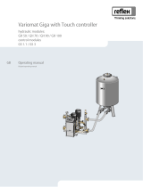
Variomat
Variomat Giga
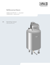
Reflexomat
Servitec V2.00
GB
Operating manual
Original operating manual


Contents
I/O module (Expansion module) — 02.02.2015 English — 3
English
I/O module (Expansion module)
02.02.2015
Contents
1Notes on the operating manual .................................................................................................................................................... 5
2Models .............................................................................................................................................................................................. 5
3Technical data ................................................................................................................................................................................. 6
4Connection ...................................................................................................................................................................................... 7
4.1Electrical connection ............................................................................................................................................................................ 8
4.2Connecting the RS-485 with the I/O module .................................................................................................................................. 12
4.3Connecting the RS-485 with the Control Basic controller ............................................................................................................ 13
4.4Connecting the RS-485 with the Control Touch controller .......................................................................................................... 14
5Settings .......................................................................................................................................................................................... 15
5.1Setting the terminators in RS-485 networks .................................................................................................................................. 15
5.2Setting the analogue outputs ........................................................................................................................................................... 18
5.3Setting the module address .............................................................................................................................................................. 19
5.4Standard setting of the I/O module ................................................................................................................................................. 20
6Replacing the fuses ....................................................................................................................................................................... 25
7Annex ............................................................................................................................................................................................. 26
7.1Reflex Customer Service .................................................................................................................................................................... 26

Notes on the operating manual
4 — English I/O module (Expansion module) — 02.02.2015

Notes on the operating manual
I/O module (Expansion module) — 02.02.2015 English — 5
1 Notes on the operating manual
The electric connections and the wiring of the device must be executed by a specialist in accordance with all applicable national and
local regulations.
Note!
Every person installing this equipment or performing any other work at the equipment is required to carefully read this
operating manual prior to commencing work and to comply with its instructions. The manual is to be provided to the
device operator and must be stored near the device for access at any time.
2 Models
The I/O modules are used to expand the inputs and outputs of the controllers for pressure-maintaining and degassing stations.
The following device groups with control units are suitable for an expansion with I/O modules:
• Reflexomat
• Variomat
• Servitec
The I/O modules support the following controllers:
• Control Basic
• Control Touch
The I/O modules are fitted with two isolating amplifiers for analogue signals:
• Pressure measurement
• Level sensor
Six digital inputs and six digital outputs are used to process messages and alarms:
• Inputs:
– 3 inputs, N.C. with 24 V self potential for standard settings.
• External temperature monitoring
• Minimum pressure signal
• Manual make-up with water.
– 3 inputs, N.O. with 230 V self potential for standard settings.
• Emergency-Off
• Manual operation (of pump or compressor, for example)
• Manual operation of the overflow valve
• Outputs:
– Potential-free as changeover contacts. Standard settings for messages:
• Make-up fault
• Below minimum pressure
• Above maximum pressure
• Manual or Stop operation
Note!
• The I/O module is connected to the control unit by the user.
• For the standard settings of the I/O modules, see chapter 5.4 "Standard setting of the I/O module" on page 20 .
• All digital inputs and outputs can be set freely as option. Settings to be made by the Reflex Customer Service, see
chapter 7.1 "Reflex Customer Service" on page 26 .

Technical data
6 — English I/O module (Expansion module) — 02.02.2015
3 Technical data
700022 _001_R001
B
H
T
Housing Plastic housing
Width (W) 340 mm
Height (H) 233.6 mm
Depth (D) 77 mm
Weight 2.0 kg
Permissible operating temperature -5° C – 55° C
Permissible storage temperature -40° C – 70° C
Degree of protection IP IP 64
Voltage supply 230 V AC, 50 – 60 Hz (IEC 38)
Fusing
• primary 0.16 A time-lag
Inputs, outputs • 6 floating relay outputs (changeover)
• 3 digital inputs 230 V AC
• 3 digital inputs 24V AC
• 2 analogue outputs, to be set with jumper
– 0V – 1 V or 2V – 10V
– 0mA – 20mA or 4mA – 20mA
Interface to the controller • RS – 485
• 19.2 kbit/s
• Floating
• connection with plug or screw terminals
• RSI-specific protocol

Connection
I/O module (Expansion module) — 02.02.2015 English — 7
4 Connection
Danger – electric shock!
• Risk of serious injury or death due to electric shock.
– Ensure that the system is voltage-free before installing the device.
– Ensure that the system is secured and cannot be reactivated by other persons.
– Ensure that installation work for the electric connection of the device is carried out by an electrician, and in
compliance with electrical engineering regulations.
Danger – electric shock!
• Risk of serious injury or death due to electric shock. Some parts of the main board may still carry 230 V voltage even
with the device physically isolated from the 230 V power supply.
– Before you remove the covers, completely isolate the device controller from the power supply.
– Verify that the main circuit board is voltage-free.

Connection
8 — English I/O module (Expansion module) — 02.02.2015
4.1 Electrical connection
The I/O modules are shipped with a power cable including earthed plug. If required, you may use a different power cable.
Proceed as follows:
1. Pull the mains plugs of the I/O module.
2. Open the housing cover.
The terminals are located on the main circuit board of the I/O module in the open housing.
I/O module main circuit board.
000256_001_R001
456
COM NC NO
19 20 21
COM NC NO
10
COM NC NO
11 12 16 17 18
COM NC NO
22 23 24 25
IN 6 IN 5 IN 4 N
13 14 15
COM
789
COM NC NO NC NO
22 23
IN 6
26 27 28 29
IN 3 IN 2 IN 1 24 V
30 31 32 33
OUT* GND GND
34 35 36 37
OUT* GND A(+)
B(-)
J5 J6
J10
J11
F1
123
LNPE
7
6
5
2
4
123 456 78
ON
1
3
1 Terminals for main connection 5 Jumper for setting the analogue signal 1
2 Feeble current fuse 250 V / 016 A time-lag 6 Jumper for setting the analogue signal 2
3 Transformer 7 Jumper for activating the terminators
4 DIP switch for setting the module address

Connection
I/O module (Expansion module) — 02.02.2015 English — 9
Terminal
number
Signal Function
1 L
Mains supply
2 N
3 PE
4 COM
Relay output 1
5 N.C.
6 N.O.
7 COM
Relay output 2
8 N.C.
9 N.O.
10 COM
Relay output 3
11 N.C.
12 N.O.
13 COM
Relay output 4
14 N.C.
15 N.O.
16 COM
Relay output 5
17 N.C.
18 N.O.
19 COM
Relay output 6
20 N.C.
21 N.O.
22 Digital input 6
Digital inputs 230V AC
23 Digital input 5
24 Digital input 4
25 Common neutral conductor for inputs 4 to 6
26 Digital input 3
Digital inputs 24V DC
27 Digital input 2
28 Digital input 1
29 24V DC supply voltage for inputs 1 to 3
30 Function earthing Cable screening for analogue outputs and RS–485 interface
31 Analogue output 2 Analogue output 2
• For pressure measurement
– No connection in Servitec with "Levelcontol" operating
mode
32 Connection to earth for analogue output 2
33 RS-485 earth RS-485 interface
34 Analogue output 1 Analogue output 1
• For level measurement
– No connection for Servitec
35 Connection to earth for analogue output 1
36 RS-485 signal B (-) RS-485 interface
37 RS-485 signal A (+)

Connection
10 — English I/O module (Expansion module) — 02.02.2015
Schematic connections of the digital inputs of the I/O module.
000246_001_R001
456
COM NC NO
19 20 21
COM NC NO
10
COM NC NO
11 12 16 17 18
COM NC NO 22 23 24 25
IN 6IN 5IN 4N
13 14 15
COM
789
COM NC NO NC NO
22 23
IN 6
26 27 28 29
IN 3IN 2IN 124 V
30 31 32 33
OUT* GND GND
34 35 36 37
OUT* GND A(+)B(-)
J5 J6
J10
J11
F1
123
LNPE
22 23 24 25
IN 6IN 5IN 4 N
22 23
IN 6
L
N
26 27 28 29
IN 3IN 2IN 1 24 V
3
1
2
123 456 78
ON
1 External connection with 230 V AC 3 Internal connection with 24 V AC
2 I/O module main circuit board

Connection
I/O module (Expansion module) — 02.02.2015 English — 11
Schematic connections of the analogue signals and the RS–485 interfaces.
000247_001_R001
456
COM NC NO
19 20 21
COM NC NO
10
COM NC NO
11 12 16 17 18
COM NC NO
22 23 24 25
IN 6 IN 5 IN 4 N
13 14 15
COM
789
COM NC NO NC NO
22 23
IN 6
26 27 28 29
IN 3 IN 2 IN 1 24 V
30 31 32 33
OUT* GND GND
34 35 36 37
OUT* GND A(+)
B(-)
J5 J6
J10
J11
F1
123
LNPE
30 31 32 33
OUT GND GND
GND
A(+)
B(-)
GND
A(+)
B(-)
OUT*
GND
34 35 36 37
OUT* GND B(-) A(+)
RS-485
OUT*
GND
1
123 456 78
ON
2
4
3
1 Analogue output 1 3 RS-485-conductor from the controller
• Control Basic
• Control Touch
2 Analogue output 2 4 RS-485 conductor for an additional I/O module
Note!
• Cable screens of the conductors must be connected separately.
• For each RS-485 conductor, the cable screen must be connected at one side.

Connection
12 — English I/O module (Expansion module) — 02.02.2015
4.2 Connecting the RS-485 with the I/O module
I/O module main circuit board.
000250_001_R001
456
COM NC NO
19 20 21
COM NC NO
10
COM NC NO
11 12 16 17 18
COM NC NO
22 23 24 25
IN 6IN 5IN 4N
13 14 15
COM
789
COM NC NO NC NO
22 23
IN 6
26 27 28 29
IN 3IN 2IN 124 V
30 31 32 33
OUT* GND GND
34 35 36 37
OUT* GND A(+)B(-)
J5 J6
J10
J11
F1
123
LNPE
J10
J11
1
2
123 456 78
ON
1 Jumper 10 in active position
• Terminator is active
2 Jumper 11 in active position
• Terminator is active
Proceed as follows:
1. Open the housing cover of the I/O module.
2. Use a screened cable to connect the RS-485 interface on the main circuit board.
• Use a three-wire connector. The connection is floating.
• Connection at the terminals 33, 36, 37 of the main circuit board.
3. Connect the cable screen at one side.
• Use terminal 30 of the I/O module.
• Optionally use terminal 22 of Control Basic.
4. Activate the terminators on the main circuit board.
• Use jumpers J 10 and J 11.
Note!
• Activate the terminators when the I/O module is at the beginning or the end of an RS-485 network.
• Connect the cable screen at one side only. Either in the I/O module or in the controller.

Connection
I/O module (Expansion module) — 02.02.2015 English — 13
4.3 Connecting the RS-485 with the Control Basic controller
Main circuit board of the Control Basic controller.
000248_001_R001
12
ON
2
1
1 DIP switches 1 and 2 in active position
• The terminator is activated
2 Connection terminals for RS-485 connection
Proceed as follows:
1. Open the housing cover of the Control Basic controller.
2. Use the screened cable fro, I/O module to connect the RS–485 with the main circuit board.
• Connection at the terminals 29, 30, 31.
3. Connect the cable screen at one side.
• Use terminal 30 of the I/O module.
• Optionally use terminal 22 of Control Basic.
4. On the main circuit board of the Control Basic controller, activate the terminators.
• Use the DP switches 1 and 2.
• Optionally, you may use the jumpers J3, 1 – 2 and 3 – 4.
Note!
• Activate the terminators when the device is at the beginning or the end of an RS-485 network.
• The main circuit board of the controller provides either the DIP switches 1 and 2 or the jumper J3.
• Connect the cable screen at one side only. Either in the I/O module or in the controller.

Connection
14 — English I/O module (Expansion module) — 02.02.2015
4.4 Connecting the RS-485 with the Control Touch controller
Main circuit board of the Control Touch controller.
000249_001_R001
12
ON
12
ON
2
1
1 Connection terminals for RS-485 connection 2 DIP switches 1 and 2 in active position
– The terminators are activated.
Proceed as follows:
1. Use a screened cable to connect the RS-485 interface on the main circuit board.
• Connection at the terminals 4, 5, 6.
2. Connect the cable screen at one side.
• Use terminal 30 of the I/O module's main circuit board.
3. Activate the terminators on the main circuit board of the Control Touch controller.
• Use the DP switches 1 and 2.
Note!
Activate the terminators when the device is at the beginning or the end of an RS-485 network.

Settings
I/O module (Expansion module) — 02.02.2015 English — 15
5 Settings
Danger – electric shock!
• Risk of serious injury or death due to electric shock. Some parts of the main board may still carry 230 V voltage even
with the device physically isolated from the 230 V power supply.
– Before you remove the covers, completely isolate the device controller from the power supply.
– Verify that the main circuit board is voltage-free.
5.1 Setting the terminators in RS-485 networks
Examples for the activation and deactivation of terminators in RS–495 networks.
• The main circuit board of the Control Basic provides either the DIP switches 1 and 2 or the jumper J3.
• Maximum length for an RS–485 connection is 1000 metres
Device controllers with I/O module.
000245_001_R001
1
33
3
1
5
2
2
4
6
7
6
7
Control Touch controller with I/O module Control Basic controller with I/O module
1 Relay outputs of the I/O module
• 6 digital outputs
• 2 analogue outputs
5 "Control Basic" controller
2 I/O module 6 RS-485 connection
3 Connections of the I/O conductors 7 Optional RS–485 connection
• Master – Slave
• Fieldbus
4 "Control Touch" controller
Terminator settings
Jumper / Switch Jumpers J10 and J11 DIP switches 1 and 2 Jumper J3
1 and 2 and 3 and 4
Settings Activated Deactivated Activated Deactivated Activated Deactivated
I/O module X
Contol Touch X
Control Basic X X

Settings
16 — English I/O module (Expansion module) — 02.02.2015
Device controllers with I/O module and bus module.
000254_001_R001
1
2
3
2
3
4
1 "Control Touch" controller 3 Bus module
2 I/O module 4 "Control Basic" controller
Terminator settings
Jumper / Switch Jumpers J10 and J11 DIP switches 1 and 2 Jumper J3
1 and 2 and 3 and 4
Setting Activated Deactivated Activated Deactivated Activated Deactivated
I/O module X
Contol Touch X
Control Basic X X
Bus module
• Lon Works
• Profibus DP
• Ethernet
X

Settings
I/O module (Expansion module) — 02.02.2015 English — 17
Device controllers and I/O modules in Master – Slave functions.
1 Control Touch controller in Master function 6 Control Basic controller in Master function
2 I/O module for the Master function 7 I/O module for the Master function
3 Control Touch controller in Slave function 8 Control Basic controller in Slave function
4 I/O module for the Slave function 9 I/O module for the Slave function
5 I/0 module for expansion
Terminator settings
Jumper / Switch Jumpers J10 and J11 DIP switches 1 and 2 Jumper J3
1 and 2 and 3 and 4
Setting Activated Deactivated Activated Deactivated Activated Deactivated
Master function:
I/O module X
Contol Touch X
Control Basic X X
Slave function:
I/O module X
I/0 module for
expansion
X
Contol Touch X
Control Basic X X
000255_00 _R0012
1
7
9
6
2
3
8
45

Settings
18 — English I/O module (Expansion module) — 02.02.2015
5.2 Setting the analogue outputs
Set the analogue outputs on the I/O module's main circuit board.
000251_001_R001
456
COM NC NO
19 20 21
COM NC NO
10
COM NC NO
11 12 16 17 18
COM NC NO
22 23 24 25
IN 6IN 5IN 4N
13 14 15
COM
789
COM NC NO NC NO
22 23
IN 6
26 27 28 29
IN 3IN 2IN 124 V
30 31 32 33
OUT* GND GND
34 35 36 37
OUT* GND A(+)B(-)
J5
J11
F1
123
LNPE
123 456 78
ON
J6
J10
J5
J5J5 J6
1
2
1 Jumper J5 2 Jumper J6
Use the jumpers J5 and J6 to set both analogue outputs as current or as voltage outputs.
Proceed as follows:
1. Pull the mains plugs of the I/O module.
2. Open the housing cover.
3. Plug the jumpers in the required position.
Analogue outputs Setting the jumpers Current output*
0 – 20 mA or 4 – 20 mA
Voltage output*
0 – 10 V or 2 – 10 V
Analogue output 1
J5 is plugged X
J5 is not plugged X
Analogue output 2
J6 is plugged X
J6 is not plugged X
* Depending on the relevant setting in the device controllers

Settings
I/O module (Expansion module) — 02.02.2015 English — 19
5.3 Setting the module address
Set the module address on the I/O module's main circuit board.
000252_001_R001
456
COM NC NO
19 20 21
COM NC NO
10
COM NC NO
11 12 16 17 18
COM NC NO
22 23 24 25
IN 6IN 5IN 4N
13 14 15
COM
789
COM NC NO NC NO
22 23
IN 6
26 27 28 29
IN 3IN 2IN 124 V
30 31 32 33
OUT* GND GND
34 35 36 37
OUT* GND A(+)B(-)
J5
J11
F1
123
LNPE
123 456 78
ON
J6
J10
J5
12345678
ON
1
1 DIP switch
DIP switch position:
• DIP switch 1 – 4
– For setting the module address
– Variable setting ON or OFF
• DIP switch 5
– Permanently on position ON.
• DIP switch 6 – 8
– For internal testing.
– On position OFF during operation.
Use DIP switches 1 – 4 to set the module address.
Proceed as follows:
1. Pull the mains plugs of the I/O module.
2. Open the housing cover.
3. Set the DIP switches 1 – 4 to position ON or OFF.
Module address
DIP switch
Used for the modules
1 2 3 4 5 6 7 8
1 1 0 0 0 1 0 0 0 1
2 0 1 0 0 1 0 0 0 2
3 1 1 0 0 1 0 0 0 3
4 0 0 1 0 1 0 0 0 4
5 1 0 1 0 1 0 0 0 5
6 0 1 1 0 1 0 0 0 6
7 1 1 1 0 1 0 0 0 7
8 0 0 0 1 1 0 0 0 8
9 1 0 0 1 1 0 0 0 9
10 0 1 0 1 1 0 0 0 10

Settings
20 — English I/O module (Expansion module) — 02.02.2015
5.4 Standard setting of the I/O module
The inputs and outputs of the I/O modules are given a default setting for every device group.
• Variomat
• Variomat Giga
• Reflexomat
• Servitec
These default settings can be changed, if required, and adjusted to local conditions.
Responses by the inputs 1 - 6 of the I/O module are recorded and displayed in the corresponding device controller's fault memory.
Note!
• Default settings apply to software version V1.10 and higher.
• All digital inputs and outputs can be set freely as option. Settings to be made by the Reflex Customer Service, see
chapter 7.1 "Reflex Customer Service" on page 26 .
/