
USER MANUAL
µChiller
+0300053EN - ENG
Up to date version available on
www.carel.com
µChiller
Controller for Chiller / Heat Pump
ENG
LEGGI E CONSERVA
Q
UESTE ISTRUZIONI
READ AND SAVE
THESE INSTRUCTIONS


ENG
GENERAL WARNINGS
!
CAREL bases the development of its products on decades of
experience in HVAC/R, on continuous investments in technological
innovations to products, procedures and strict quality processes
with in-circuit and functional testing on 100% of its products, and
on the most innovative production technology available on the
market. CAREL and its subsidiaries/affiliates nonetheless cannot
guarantee that all the aspects of the product and the software
included with the product respond to the requirements of the
final application, despite the product being developed according
to start- of- the- art techniques. The customer (manufacturer,
developer or installer of the final equipment) accepts all liability
and risk relating to the configuration of the product in order to
reach the expected results in relation to the specific final
installation and/or equipment. CAREL may, based on specific
agreements, act as a consultant for the successful commissioning of
the final unit/application, however in no case does it accept
liability for the correct operation of the final equipment/system.
The CAREL product is a state-of-the-art product, whose operation
is specified in the technical documentation supplied with the
product or can be downloaded, even prior to purchase, from the
website www.carel.com. Each CAREL product, in relation to its
advanced level of technology, requires
setup/configuration/programming/commissioning to be able to
operate in the best possible way for the specific application.
Failure to complete such operations, which are
required/indicated in the user manual, may cause the final
product to malfunction; CAREL accepts no liability in such cases.
Only qualified personnel may install or carry out technical service
on the product. The customer must only use the product in the
manner described in the documentation relating to the product.
In addition to observing any further warnings described in this
manual, the following warnings must be heeded for all CAREL
products:
l prevent the electronic circuits from getting wet. Rain,
humidity and all types of liquids or condensate contain
corrosive minerals that may damage the electronic circuits. In
any case, the product should be used or stored in
environments that comply with the temperature and humidity
limits specified in the manual;
l do not install the device in particularly hot environments. Too
high temperatures may reduce the life of electronic devices,
damage them and deform or melt the plastic parts. In any case,
the product should be used or stored in environments that
comply with the temperature and humidity limits specified in
the manual;
l do not attempt to open the device in any way other than
described in the manual.
l do not drop, hit or shake the device, as the internal circuits and
mechanisms may be irreparably damaged.
l do not use corrosive chemicals, solvents or aggressive
detergents to clean the device.
l do not use the product for applications other than those
specified in the technical manual.
All of the above suggestions likewise apply to the controllers,
serial cards, programming keys or any other accessory in the
CAREL product portfolio.
CAREL adopts a policy of continual development. Consequently,
CAREL reserves the right to make changes and improvements to
any product described in this document without prior warning.
The technical specifications shown in the manual may be changed
without prior warning. The liability of CAREL in relation to its
products is specified in the CAREL general contract conditions,
available on the website www.carel.com and/or by specific
agreements with customers; specifically, to the extent where
allowed by applicable legislation, in no case will CAREL, its
employees or subsidiaries/affiliates be liable for any lost earnings
or sales, losses of data and information, costs of replacement goods
or services, damage to things or people, downtime or any direct,
indirect, incidental, actual, punitive, exemplary, special or
consequential damage of any kind whatsoever, whether
contractual, extra-contractual or due to negligence, or any other
liabilities deriving from the installation, use or impossibility to use
the product, even if CAREL or its subsidiaries/affiliates are warned
of the possibility of such damage.
DISPOSAL
INFORMATION FOR USERS ON THE CORRECT HANDLING
OF WASTE ELECTRICAL AND ELECTRONIC EQUIPMENT
(WEEE)
The product is made up of metal parts and plastic parts. In
reference to European Union directive 2002/96/EC issued on 27
January 2003 and related national legislation, please note that:
l WEEE cannot be disposed of as municipal waste and such
waste must be collected and disposed of separately;
l the public or private waste collection systems defined by local
legislation must be used. In addition, the equipment can be
returned to the distributor at the end of its working life when
buying new equipment;
l the equipment may contain hazardous substances: the
improper use or incorrect disposal of such may have negative
effects on human health and on the environment;
l the symbol (crossed-out wheeled bin) shown on the product
or on the packaging and on the instruction sheet indicates that
the equipment has been introduced onto the market after 13
August 2005 and that it must be disposed of separately;
l in the event of illegal disposal of electrical and electronic
waste, the penalties are specified by local waste disposal
legislation.
Warranty on materials: 2 years (from production date, excluding
consumables).
Approval: the quality and safety of CAREL S.p.A. products are
guaranteed by the ISO 9001 certified design and production
system.
µChiller +0300053EN rel. 1.0– 23.07.2018
|3

ENG
IMPORTANT
NO POWER
& SIGNAL
C
ABLES
TOGETHER
READ CAREFULLY IN THE TEXT!
Separate as much as possible the probe and digital input cables
from cables to inductive loads and power cables, so as to avoid
possible electromagnetic disturbance. Never run power cables
(including the electrical panel cables) and signal cables in the
same conduits.
Key to the symbols:
Important: to bring critical issues to the attention of those
using the product.
Note: to focus attention on important topics; in particular the
practical application of the various product functions.
Important: This product is to be integrated and/or
incorporated into the final apparatus or equipment.
Verification of conformity to the laws and technical standards
in force in the country where the final apparatus or equipment
will be operated is the manufacturer’s responsibility. Before
delivering the product, Carel has already completed the
checks and tests required by the relevant European directives
and harmonised standards, using a typical test setup, which
however cannot be considered as representing all possible
conditions of the final installation.
4|
µChiller +0300053EN rel. 1.0– 23.07.2018

ENG
Index
1. INTRODUCTION 7
1.1 Main functions 7
1.2 Models 8
1.3 Accessories 8
2. INSTALLATION 12
2.1 Warnings 12
2.2 Panel version 12
2.3 DIN rail version 13
2.4 Electrical installation 13
2.5 Probe connection 15
2.6 Positioning inside the panel 16
2.7 Electrical installation 16
2.8 Connecting serial ports with two circuits 16
2.9 Connection to Power+ (for BLDC) 17
2.10 Positioning of probes/components 18
2.11 Functional diagrams 19
3. COMMISSIONING 35
3.1 APPLICA app 35
3.2 Applica Desktop 38
4. USER INTERFACE 41
4.1 Introduction 41
4.2 User terminal 41
4.3 Standard display 42
5. FUNCTIONS 46
5.1 Temperature control 46
5.2 User pumps 49
5.3 Frost protection control 50
5.4 Compressor rotation 53
5.5 Compressor management 54
5.6 BLDC compressor protectors 56
5.7 BLDC comp. alarm prevention 58
5.8 Compressor alarms 61
5.9 Power+ Speed drive 61
5.10 Expansion valve driver 61
5.11 Control of the expansion valve 62
5.12 Source pump 62
5.13 Source fans 62
5.14 Free cooling 66
5.15 Types of free cooling 66
5.16 Free cooling functions 69
5.17 Defrost 70
5.18 4-way valve management 76
5.19 Manual device management 76
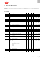
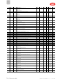
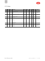
6. PARAMETER TABLE 77
6.1 System 77
6.2 Compressor 79
6.3 BLDC and Inverter 81
6.4 Valve 81
6.5 Source 82
6.6 I/O settings 84
6.7 BMS port 86
6.8 Password 86
6.9 Dashboard values 86
6.10 Settings 88
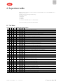
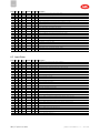
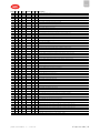
6. SUPERVISOR TABLE 89
6.1 Coil Status 89
6.2 Input Status 90
6.3 Holding Register 92
6.4 Input Register 96
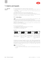
7. ALARMS AND SIGNALS 98
7.1 Types of alarms 98
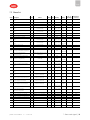
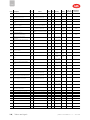
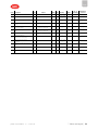
7.2 Alarm list 99
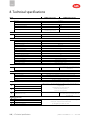
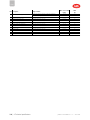
8. TECHNICAL SPECIFICATIONS 102
8.1 Connector/cable table 103
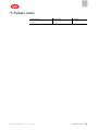
9. RELEASE NOTES 105
µChiller +0300053EN rel. 1.0– 23.07.2018
|5


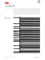
1. Introduction
μChiller is the Carel solution for complete management of air/water and water/water chillers and heat
pumps. The maximum configuration manages 2 compressors per circuit (On/Off or BLDC), up to a
maximum of 2 circuits (using an expansion card for circuit 2). The distinctive element of μChiller is
complete control of high-efficiency units through integrated management of electronic expansion valves
and brushless BLDC compressors, thus ensuring greater compressor protection and reliability and a high-
efficiency unit. The user terminal allows wireless connectivity with mobile devices and is built-in on the
panel mounted models, or sold separately on DIN rail mounted models. CAREL’s "APPLICA" app, available
on Google Play for the Android operating system, makes it easier to configure parameters and
commission the unit in the field.
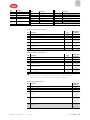
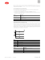
1.1
Main functions
Ref. Description
Main features Up to two circuits and 2 + 2 compressors
Compressors in tandem configuration with possible BLDC compressor
Air/water chiller or heat pump (A/W)
Water/water chiller or heat pump (W/W)
1 evaporator per unit
Air-cooled condenser with separate/shared air circuit for A/W units
Water-cooled condenser with single circuit for W/W units
Hardware Panel mounted model: management of ON-OFF compressors
DIN rail mounted model: management of ON-OFF compressors
DIN rail mounted model, enhanced: management of ON-OFF compressors
DIN rail mounted model, high efficiency: management of BLDC compressors
User interface
7-segment, 2-row LED display, optional pGDx graphic display, communication via APPLICA
app (compatible with NFC and BTLE) for mobile devices
Temperature control PID at start-up
PID in operation
Set point compensation on outdoor temperature
Compressorrotation FIFO or timed
Compressor
management
Specific BLDC compressors (see list on KSA - μChiller section)
Generic scroll compressors
Oil management with
BLDC
Oil recovery function (extended operation at part load)
Oil equalisation (tandem with BLDC compressor)
Circuit destabilisation Forced compressor rotation (extended operation at part load)
ExVdriver Built-in valve driver on enhanced and high efficiency models
External driver management via FieldBus port (all versions)
Programming with time
bands
Unit ON-OFF or 2nd set point (1 time band per day)
"Noise reduction" function for condenser fans (1 time band per day)
User pumps 1/2 pumps (2 pumps only with 2 circuits)
Rotation by time or with pump overload alarm
Water-cooled condenser 1 common pump for both circuits
Air-cooled condenser Independent fans on each circuit or common to both circuits
Fan modulation based on condensing temperature (On/Off fan control via CAREL
CONVONOFF0 module)
Optimised start-up to quickly bring the compressor(s) to steady operation
Fan anti-block protection (harsh climate)
Defrost Simultaneous
Separate
Independent
Defrost interval managed based on outside temperature ("sliding defrost")
Prevent Prevention of scroll compressor operating limits in relation to condensing and evaporation
temperature
Evaporator frost prevention
Total management of the BLDC compressor envelope limits
Alarms Management of automatic and manual reset according to alarm severity (see the chapter on
ENG
µChiller +0300053EN rel. 1.0– 23.07.2018
1. Introduction|7

ENG
Ref. Description
Alarms)
Alarm log (up to 20 events): alarm and reset date and time recorded
Connectivity/supervision RS485 serial port
Modbus RTU
Baud rate up to 115200 bit/s
Frame configurable by Parity (None, Even, Odd) and StopBits (1 or 2); Databits fixed at 8 bits.
Tab.1.a
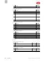
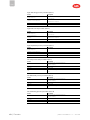
1.2
Models
P/N Mounting Connectivity
Compressor
management:
Notes
Electronic expansion
valve management
UCHBP00000090 panel NFC On/Off
bipolar: with EVD
Evolution driver
UCHBP00000100 panel
NFC, Bluetooth
(BLE)
On/Off
bipolar: with EVD
Evolution driver
UCHBD00001130 DIN rail - On/Off
bipolar: with EVD
Evolution driver
UCHBDE0001140 DIN rail - On/Off
enhanced
version
unipolar: built-in; bipolar:
with external EVD
Evolution driver
UCHBDH0001140 DIN rail - On-Off and BLDC
high
efficiency
version
unipolar: built-in; bipolar:
with external EVD
Evolution driver
UCHBE00001130: 2nd
circuit expansion
DIN rail - On/Off
bipolar: with external EVD
Evolution driver
UCHBE00001140: 2nd
circuit expansion
DIN rail - On/Off
enhanced
version
unipolar: built-in; bipolar:
with external EVD
Evolution driver
Tab.1.b
1.3
Accessories
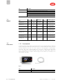
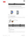
1.3.1 User terminal
For DIN rail mounted models (built-in on the panel model). The user terminal includes the display and
keypad, comprising four buttons that, when pressed alone or combined with other buttons, access the
operations available for the “User” and “Service” profiles (see the paragraph on “Commissioning”).
Connectivity - NFC or NFC + Bluetooth (BLE) based on the model - allows interaction with mobile
devices and simplifies unit commissioning (after having installed the CAREL “Applica” APP for the
Android operating system, see chapters "Commissioning" and "User interface"). For assembly, see the
technical leaflet +0500146IE.
Fig.1.a
P/N Description
AX5000PD20A20 User terminal (NFC)
AX5000PD20A30 User terminal (NFC, Bluetooth BLE)
8|1. Introduction
µChiller +0300053EN rel. 1.0– 23.07.2018

P/N Description
ACS00CB000020 Connection cable L=1.5 m
ACS00CB000010 Connection cable L=3 m
Tab.1.c
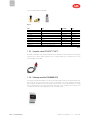
1.3.2 EVD Evolution/EVD Evolution twin valve driver
The Enhanced and High Efficiency models have the driver built-into the controller, able to drive unipolar
valves (up to Carel model E3V, with a cooling capacity less than 90-100kW); all versions can be connected
to the external EVD Evolution driver to drive bipolar valves (with a higher cooling capacity).
Fig.1.b
1.3.3 Temperature sensors
NTC sensors for measuring the temperatures in the user circuit, the outdoor air or source, and the
refrigeration circuit. NTC**HT sensors are recommended for discharge temperature measurement (with
BLDC compressors in heat pump mode).
Fig.1.c
P/N Type Range
NTC060HF01 10 kΩ ±1% @25°C, IP67 -50 to 90°C strap-on
NTC060HP00 10 kΩ ±1% @25°C, IP67 -50 to 50 °C (105°C in air)
NTC060HT00 50 kΩ ±1% @25°C, IP67
-30 to 100°C RH95% in air (150°C in a
dry environment)
Tab.1.d
Note: see manual +040010025 (ITA- ENG) /+040010026 (FRE-GER) for guidelines on installing the
sensors on the unit.
1.3.4 Pressure sensors
These measure:
1. evaporation pressure in the circuit, used to control superheat, manage the evaporator frost protection
function and the operating limits;
2. condensing pressure in the circuit, to control the condensing stage and manage the operating limits.
ENG
µChiller +0300053EN rel. 1.0– 23.07.2018
1. Introduction|9

ENG
See the technical leaflets +050000488.
Fig.1.d
P/N Type Application Range
SPKT0*13P* 0-5V LP R407C, R290 -1 to 9.3 bars
SPKT0*43P* 0-5V LP R410A, R32 0 to 17.3 bars
SPKT0*33P* 0-5V HP R407C, R290 0 to 34.5 bars
SPKT0*B6P* 0-5V HP R410A, R32 0 to 45 bars
SPKT0011C* 4-20mA LP R407C, R290 0 to 10 bars
SPKT0041C* 4-20mA LP R410A, R32 0 to 18.2 bars
SPKT0031C* 4-20mA HP R407C, R290 0 to 30 bars
SPKT00B1C* 4-20mA HP R410A, R32 0 to 44.8 bars
SPKC00*310 IP67 connection cable L=2 to 12 m
SPKC00*311 IP67 connection cable - 50 pcs L=0.65 to 1.3 m
Tab.1.e
1.3.5 Unipolar valve (P/N E2V**FSAC*)
Used with a compatible stator from the E2VSTA03**series. Unipolar electronic expansion valve, managed
directly by the controller, which guarantees precise refrigerant flow even at low flow-rates. See the
technical leaflets +050001680.
Fig.1.e
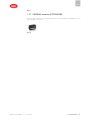
1.3.6 Ultracap module (EVD0000UC0)
The Ultracap module EVD0000UC0 is an optional external backup module for the EVD Evolution driver
that ensures the valves are closed in the event of a power failure. The module guarantees temporary
power supply to one EVD Evolution driver (single or twin) only in the event of a power failure, for enough
time to immediately close the connected electronic valves (one or two). It therefore also avoids the need
to install a solenoid valve in the refrigeration circuit, or a backup coil kit.
10|1. Introduction
µChiller +0300053EN rel. 1.0– 23.07.2018

Fig.1.f
1.3.7 USB/RS485 converter (CVSTDUMOR0)
Electronic device used to interface an RS485 network to a personal computer via the USB port. See the
technical leaflets +050000590.
Fig.1.g
ENG
µChiller +0300053EN rel. 1.0– 23.07.2018
1. Introduction|11

ENG
2. Installation
2.1
Warnings
Important: avoid installing the controller in environments with the following characteristics:
l temperature and humidity that do not comply with the ambient operating conditions (see
"Technical specifications");
l strong vibrations or knocks;
l exposure to water sprays or condensate;
l exposure to aggressive and polluting atmospheres (e.g.: sulphur and ammonia gases, saline mist,
smoke) which may cause corrosion and/or oxidation;
l strong magnetic and/or radio frequency interference (thus avoid installation near transmitting
antennae);
l exposure to direct sunlight and the elements in general;
l wide and rapid fluctuations in ambient temperature;
l exposure to dust (formation of corrosive patina with possible oxidation and reduction of insulation).
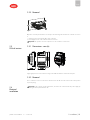
2.2
Panel version
2.2.1 Dimensions - mm (in)
Fig.2.a
2.2.2 Mounting
Important: before carrying out any maintenance, disconnect the controller from the power supply by
moving the main system switch to “off”.
Fig.2.b
1. Place the controller in the opening, pressing lightly on the side anchoring tabs.
2. Then press on the front until fully inserted (the side tabs will bend, and the catches will attach the
controller to the panel).
Important: IP65 front protection is guaranteed only if the following conditions are met:
l maximum deviation of the rectangular opening from flat surface: ≤ 0.5 mm;
l thickness of the electrical panel sheet metal: 0.8-2 mm;
l maximum roughness of the surface where the gasket is applied: ≤ 120 μm.
Note: the thickness of the sheet metal (or material) used to make the electrical panel must be
adequate to ensure safe and stable mounting of the product..
12|2. Installation
µChiller +0300053EN rel. 1.0– 23.07.2018

2.2.3 Removal
Fig.2.c
Open the electrical panel from the rear and press the anchoring tabs and then the controller to remove
it.
1. Gently press the side anchoring tabs on the controller;
2. Exert slight pressure on the controller until it is removed.
Important: the operation does not require the use of a screwdriver or other tools.
2.3
DIN rail version
2.3.1 Dimensions - mm (in)
Fig.2.d
Apply slight pressure to the controller resting on the DIN rail until the rear tab clicks into place.
2.3.2 Removal
Use a screwdriver as a lever in the hole to lift and release the tab. The tab is held in the locked position
by return springs.
2.4
Electrical
installation
Important: before carrying out any maintenance, disconnect the controller from the power supply by
moving the main system switch to “off”.
ENG
µChiller +0300053EN rel. 1.0– 23.07.2018
2. Installation|13

ENG
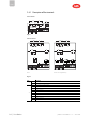
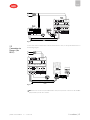
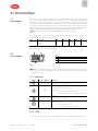
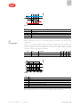
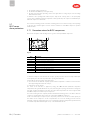
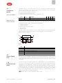
2.4.1 Description of the terminals
Panel model
J1
J7
G0 G
J6
C
C
NO1
NO2
NO3
NO4
NO5
J2
J3
J4 BMSJ5 FBus
S1 S3 5V
S2Y2
Y1ID1
ID2
ID3ID5
ID4S4
S6 +V
VL
S5
Fig.2.e
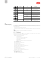
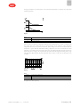
DIN rail model
J1
J7
G0 G
J6
C
C
NO1
NO2
NO3
NO4
NO5
J2
J3
J4 BMSJ5 FBus
S1 S3 5V
S2Y2
Y1ID1
ID2
ID3ID5
ID4S4
S6 +V
VL
S5
J11
C NO6
J9
J8
S7
ID6
J1
J7
G0 G
J6
C
C
NO1
NO2
NO3
NO4
NO5
J2
J3
J4 BMSJ5 FBus
S1 S3 5V
S2Y2
Y1ID1
ID2
ID3ID5
ID4S4
S6 +V
VL
S5
J11
C NO6
J10
J9
J14
J8
S7
ID6
Basic Enhanced / High Efficiency
Fig.2.f
Ref. Description
J1
G Power supply
G0 Power supply: reference
J2
5V Ratiometric probe power supply
S3 Analogue input 3
S1 Analogue input 1
Y1 Analogue output 1
ID1 Digital input 1
O GND: reference for probes, digital inputs and analogue outputs
S5 Analogue input 5
S2 Analogue input 2
Y2 Analogue output 2
ID2 Digital input 2
14|2. Installation
µChiller +0300053EN rel. 1.0– 23.07.2018

Ref. Description
J3
ID3 Digital input 3
ID5 Digital input 5
+V Power supply to 4-20 mA active probes
S6 Analogue input 6
VL Not used
ID4 Digital input 4
O GND: reference for analogue and digital inputs
S4 Analogue input 4
J4
- BMS serial port (RS485): Rx/Tx-
+ BMS serial port (RS485): Rx/Tx+
O BMS serial port (RS485): GND
J5
- Fieldbus serial port (RS485): Rx/Tx -
+ Fieldbus serial port (RS485): Rx/Tx +
O Fieldbus serial port (RS485): GND
J6
C Common for relays 1, 2, 3, 4
NO1 Digital output (relay) 1
NO2 Digital output (relay) 2
NO3 Digital output (relay) 3
NO4 Digital output (relay) 4
J7
C Common for relay 5
NO5 Digital output (relay) 5
J8 - Remote terminal connector
J9
O Input reference
ID6 Digital input 6
O Input reference
S7 Analogue input 7
J10(*)
G
Ultracap module power supply (future use)
G0
Vbat Emergency power supply from Ultracap module (future use)
J11
- (not used)
C Common for relay 6
NO6 Digital output (relay) 6
J14(*) Carel ExV unipolar valve connector
Tab.2.a
(*) for DIN Enhanced / High Efficiency models only
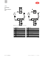
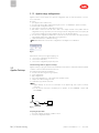
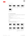
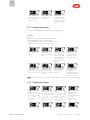
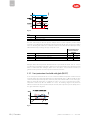
2.5
Probe
connection
NTC probes 4-20 mA probes
Fig.2.g
Fig.2.h
0-10 Vdc probes 0-5 V ratiometric pressure probes
Fig.2.i
Fig.2.j
ENG
µChiller +0300053EN rel. 1.0– 23.07.2018
2. Installation|15

ENG
Note: O = GND
2.6
Positioning
inside the panel
The position of the controller in the electrical cabinet must be chosen so as to guarantee correct physical
separation from the power components (solenoids, contactors, actuators, inverters, ...) and the connected
cables. Proximity to such devices/cables may create random malfunctions that are not immediately
evident. The structure of the panel must allow the correct flow of cooling air.
2.7
Electrical
installation
Attenzione:
When laying the wiring, "physically" separate the power part from the control part. The proximity of
these two sets of wires will, in most cases, cause problems of induced disturbance or, over time,
malfunctions or damage to the components. The ideal solution is to house these two circuits in two
separate cabinets. Sometimes this is not possible, and therefore the power part and the control part must
be installed in two separate areas inside the same panel.
For the control signals, it is recommended to use shielded cables with twisted wires. If the control cables
have to cross over the power cables, the intersections must be as near as possible to 90 degrees, always
avoiding running the control cables parallel to the power cables.
Pay attention to the following warnings:
l use cable ends suitable for the corresponding terminals. Loosen each screw and insert the cable ends,
then tighten the screws. When the operation is completed, slightly tug the cables to check they are
sufficiently tight;
l separate as much as possible the probe signal, digital input and serial line cables from the cables
carrying inductive loads and power cables to avoid possible electromagnetic disturbance. Never run
power cables (including the electrical cables) and probe signal cables in the same conduits. Do not
install the probe cables in the immediate vicinity of power devices (contactors, circuit breakers or
similar);
l reduce the path of the probe cables as much as possible, and avoid spiral paths that enclose power
devices;
l avoid touching or nearly touching the electronic components fitted on the boards to avoid
electrostatic discharges (extremely damaging) from the operator to the components;
l do not secure the cables to the terminals by pressing the screwdriver with excessive force, to avoid
damaging the controller: maximum tightening torque 0.22-0.25 N•m;
l for applications subject to considerable vibrations (1.5 mm pk- pk 10/55 Hz), secure the cables
connected to the controller around 3 cm from the connectors using clamps;
l all the extra low voltage connections (analogue and digital inputs, analogue outputs, serial bus
connections, power supplies) must have reinforced or double insulation from the mains network.
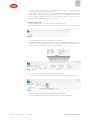
2.8 Connecting
serial ports with
two circuits
For serial connections (FBus and BMS ports), the cables used must be suitable for the RS485 standard
(shielded twisted pair, see the specifications in the following table). The earth connection of the shield
must be made using the shortest connection possible on the metal plate at the bottom of the electrical
panel.
Master
device
Serial
port
Lmax
(m)
Wire/wire
capacitance
(pF/m)
Resistance on first
and last device
Max no. of slave
devices on bus
Data rate
(bit/s)
μChiller FBus 10 <90 120 Ω 16 19200
PC
(supervision)
BMS 500 <90 120 Ω 16 115200
Note: 120 Ω 1/4W terminating resistors on the first and last devices in the network must be used
when the length exceeds 100 m.
For two-circuit units, the power supply connections must be in phase between the two controllers (G0 on
the master controller and G0 on the slave controller connected to the same power supply wire); the serial
connection between the two controllers (J5 FBus on the master and J4 BMS on the slave) must be made
as shown in the figure (+ with + and - with -).
16|2. Installation
µChiller +0300053EN rel. 1.0– 23.07.2018

Fig.2.k
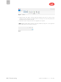
2.9
Connection to
Power+ (for
BLDC)
For the serial connection between the controller and the Power+ driver, see the specific manual. Also see
the following diagram.
Fig.2.l
Note: in the two-circuit version, the EVD Evolution driver, if used, must be connected to the FieldBus
port (terminal J5) on the slave controller.
ENG
µChiller +0300053EN rel. 1.0– 23.07.2018
2. Installation|17

ENG
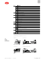
2.10
Positioning
of
probes/compon
ents
Fig.2.m: water-cooled unit (left) and air-cooled unit (right)
Ref. Description
S Source
U User
E Evaporator
F Filter-drier
L Liquid receiver
CP Compressor
C Condenser
SL Liquid sightglass
P1 Condensing pressure probe
V Solenoid valve
V1 Thermostatic expansion valve
Ref. Description
PU User pump
PS Source pump
P2 Evaporation pressure probe
T1 Discharge temperature probe
T2 Suction temperature probe
P3 High pressure switch
T3 Return temperature sensor (from) source/outside
F1 User pump flow switch
T4 Water delivery temperature (to) user
T5 Water return temperature (from) user
Tab.2.b
18|2. Installation
µChiller +0300053EN rel. 1.0– 23.07.2018

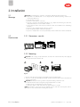
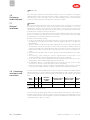
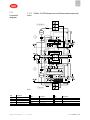
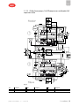
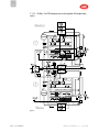
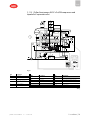
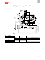
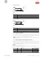
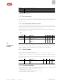
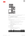
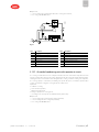
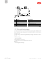
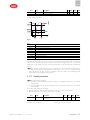
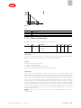
2.11
Functional
diagrams
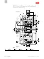
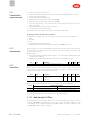
2.11.1 Chillers, On/Off compressors and thermostatic expansion
valve
Fig.2.n
Ref. Description
C1/C2 Condenser 1/2
E1/E2 Evaporator 1/2
V1_C1 Solenoid valve circuit 1
V1_C2 Solenoid valve circuit 2
V2_C1
Thermostatic expansion
Ref. Description
SL1/2 Liquid sightglass 1/2
F1/2 Filter-drier 1/2
FL Flow switch
CP1/2 Compressor 1/2
Ref. Description
R1/2 Frost protection heater 1/2
P Pressure probe/pressure switch
T Temperature probe/thermostat
AL Alarm
ENG
µChiller +0300053EN rel. 1.0– 23.07.2018
2. Installation|19

ENG
Ref. Description
valve circuit 1
V2_C2
Thermostatic expansion
valve circuit 2
Ref. Description
PU1/2 User pump 1/2
L1/2 Liquid receiver 1/2
Ref. Description
AL1_C1/2 Remote alarm circuit 1/2
Tab.2.c
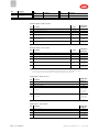
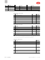
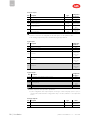
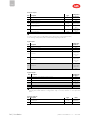
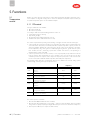
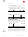
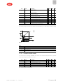
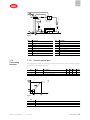
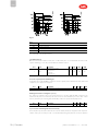
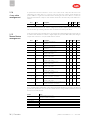
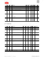
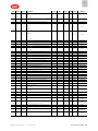
Analogue inputs - Master circuit 1
Ref. Description Type
Configuration
parameters
S1 Return temperature from user NTC --
S2 Delivery temperature to user NTC --
S3 Not present - Hc00
S4 Condensing pressure 0-5V
Hc01; Hc02;
C040; C041; C042
S5 Evaporation pressure 0-5V
Hc01; C037; C038;
C039
S6 Not present -
Hc03; U025;
U026; U027
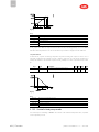
Analogue inputs - Slave circuit 2
Ref. Description Type
Configuration
parameters
S1 Not present - --
S2 Not present - --
S3 Not present - Hc00
S4 Condensing pressure 0-5V
Hc01; Hc02;
C040; C041; C042
S5 Evaporation pressure 0-5V
Hc01; C037;
C038; C039
S6 Not present -
Hc05; U025;
U026; U027
Note:
l probes S1 and S2 are not configurable, for the other probes, see the parameter table;
l the discharge temperature probe is automatically assigned type NTC-HT.
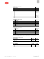
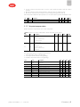
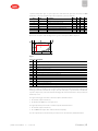
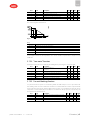
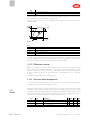
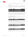
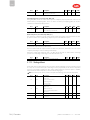
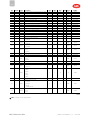
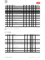
Digital inputs - Master circuit 1
Ref. Description
Configuration
parameters
ID1 User pump flow switch U060
ID2 Compressor 1 overload C035
ID3 High pressure switch C034
ID4 Not present
Hc06; C035;
U059; U058;
U062; U057;
U061
ID5 Remote alarm
Hc07; C035;
U059; U058;
U062; U057;
U061
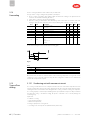
Digital inputs - Slave circuit 2
Ref. Description
Configuration
parameters
ID1 Pump 2 overload U061
ID2 Compressor 1 overload C035
ID3 High pressure switch C034
ID4 Not present
Hc09; C035;
U059; U058;
20|2. Installation
µChiller +0300053EN rel. 1.0– 23.07.2018
Page is loading ...
Page is loading ...
Page is loading ...
Page is loading ...
Page is loading ...
Page is loading ...
Page is loading ...
Page is loading ...
Page is loading ...
Page is loading ...
Page is loading ...
Page is loading ...
Page is loading ...
Page is loading ...
Page is loading ...
Page is loading ...
Page is loading ...
Page is loading ...
Page is loading ...
Page is loading ...
Page is loading ...
Page is loading ...
Page is loading ...
Page is loading ...
Page is loading ...
Page is loading ...
Page is loading ...
Page is loading ...
Page is loading ...
Page is loading ...
Page is loading ...
Page is loading ...
Page is loading ...
Page is loading ...
Page is loading ...
Page is loading ...
Page is loading ...
Page is loading ...
Page is loading ...
Page is loading ...
Page is loading ...
Page is loading ...
Page is loading ...
Page is loading ...
Page is loading ...
Page is loading ...
Page is loading ...
Page is loading ...
Page is loading ...
Page is loading ...
Page is loading ...
Page is loading ...
Page is loading ...
Page is loading ...
Page is loading ...
Page is loading ...
Page is loading ...
Page is loading ...
Page is loading ...
Page is loading ...
Page is loading ...
Page is loading ...
Page is loading ...
Page is loading ...
Page is loading ...
Page is loading ...
Page is loading ...
Page is loading ...
Page is loading ...
Page is loading ...
Page is loading ...
Page is loading ...
Page is loading ...
Page is loading ...
Page is loading ...
Page is loading ...
Page is loading ...
Page is loading ...
Page is loading ...
Page is loading ...
Page is loading ...
Page is loading ...
Page is loading ...
Page is loading ...
Page is loading ...
Page is loading ...
Page is loading ...
Page is loading ...
-
 1
1
-
 2
2
-
 3
3
-
 4
4
-
 5
5
-
 6
6
-
 7
7
-
 8
8
-
 9
9
-
 10
10
-
 11
11
-
 12
12
-
 13
13
-
 14
14
-
 15
15
-
 16
16
-
 17
17
-
 18
18
-
 19
19
-
 20
20
-
 21
21
-
 22
22
-
 23
23
-
 24
24
-
 25
25
-
 26
26
-
 27
27
-
 28
28
-
 29
29
-
 30
30
-
 31
31
-
 32
32
-
 33
33
-
 34
34
-
 35
35
-
 36
36
-
 37
37
-
 38
38
-
 39
39
-
 40
40
-
 41
41
-
 42
42
-
 43
43
-
 44
44
-
 45
45
-
 46
46
-
 47
47
-
 48
48
-
 49
49
-
 50
50
-
 51
51
-
 52
52
-
 53
53
-
 54
54
-
 55
55
-
 56
56
-
 57
57
-
 58
58
-
 59
59
-
 60
60
-
 61
61
-
 62
62
-
 63
63
-
 64
64
-
 65
65
-
 66
66
-
 67
67
-
 68
68
-
 69
69
-
 70
70
-
 71
71
-
 72
72
-
 73
73
-
 74
74
-
 75
75
-
 76
76
-
 77
77
-
 78
78
-
 79
79
-
 80
80
-
 81
81
-
 82
82
-
 83
83
-
 84
84
-
 85
85
-
 86
86
-
 87
87
-
 88
88
-
 89
89
-
 90
90
-
 91
91
-
 92
92
-
 93
93
-
 94
94
-
 95
95
-
 96
96
-
 97
97
-
 98
98
-
 99
99
-
 100
100
-
 101
101
-
 102
102
-
 103
103
-
 104
104
-
 105
105
-
 106
106
-
 107
107
-
 108
108


Carel MuChiller UCHBE00001130 User manual
- Type
- User manual
- This manual is also suitable for
Ask a question and I''ll find the answer in the document
Finding information in a document is now easier with AI
Related papers
Other documents
-
VIAIR 93940 User guide
-
 Atex D4 Installation guide
-
BENDIX TCH-003-039 User manual
-
Premier PHP HWC-150 User manual
-
 STORK TRONIC ST121-KD1KAR.112 Product information
-
 Master-Bilt Master Controller-Legacy 1.0 Systems User manual
-
Tefcold NOC60CC-P Owner's manual
-
Danfoss Electronic Unit for BD350GH Compressor, 101N0710, 24V DC Installation guide
-
MULTISPAN CC-552 Owner's manual
-
 Evco EV3B73N9 Instructions Sheet


