Page is loading ...

1
IMPORTANT:
Refer to www.extron.com for the
complete user guide, installation
instructions, and specifications.
SMB 100 Series • Installation Guide
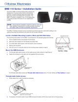
The Extron SMB Series Surface Mount Boxes are designed for mounting various Extron architectural products, including wall
plates, Architectural Adapter Plates (AAP), AAP Mounting Frames, and MediaLink® Controllers. Each box can be surface
mounted on a tabletop or wall for convenient access to connectors and controls.
The back and bottom of the boxes feature AAP openings. Blank AAP panels are included to ll unused openings.
This guide provides information for a qualied, experienced installer to install an SMB surface mount box.
SMB 104
Four-gang
Surface Mount Box
SMB 105
Five-gang
Surface Mount Box
SMB 103
Three-gang
Surface Mount Box
SMB 102
Two-gang
Surface Mount Box
SMB 101
Single-gang
Surface Mount Box
SMB 107
Seven-gang
Surface Mount Box
Recommended Fasteners
Choose the appropriate type of screw or bolt for the mounting surface (see the table below). The mounting holes in the bottom
panel of the SMB accommodate #6 or 1/4 inch screws.
Wall Type Fasteners Min. Size Fastener
Quantity
Drill Bit Size Notes
Drywall Toggle bolts 3/16 inch At least 3 1/2 inch Min. 3/8 inch wall thickness
Solid wood Wood screws #6 with a washer At least 3 3/32 inch Min. 3/8 inch wall thickness
Masonry Masonry screws 1/4 inch At least 3 3/16 inch masonry bit Do not mount to masonry joints.
Grounding
The bottom plate includes a #6‑32 stud insert for grounding; a grounding nut is included with each SMB.
Mounting the SMB
NOTES:
• This unit must be installed in accordance with the National Electrical Code and with all local codes.
• Ensure that the installation meets the local and state regulatory requirements, including building, electrical,
and safety codes, and ADA accessibility requirements.
• Ensure that there are no utility cables or pipes at the intended location that might be damaged or cause injury
when installing the box.
The SMB can be mounted on any interior wall type or on a tabletop. Knockouts allow for raceways to be run from the top or
rear of the box. Install the cables into the wall or raceway before mounting the box or installing any devices in the SMB. The
installation instructions apply to all models.

SMB Series Surface Mount Boxes • Installation Guide (Continued)
ExtronHeadquarters
+800.633.9876 Inside USA/Canada Only
ExtronUSA-West ExtronUSA-East
+1.714.491.1500 +1.919.850.1000
+1.714.491.1517 FAX +1.919.850.1001 FAX
ExtronEurope
+800.3987.6673
Inside Europe Only
+31.33.453.4040
+31.33.453.4050 FAX
ExtronAsia
+800.7339.8766
Inside Asia Only
+65.6383.4400
+65.6383.4664 FAX
ExtronJapan
+81.3.3511.7655
+81.3.3511.7656 FAX
ExtronChina
+4000.EXTRON
+4000.398766
Inside China Only
+86.21.3760.1568
+86.21.3760.1566 FAX
ExtronMiddleEast
+971.4.2991800
+971.4.2991880 FAX
ExtronKorea
+82.2.3444.1571
+82.2.3444.1575 FAX
ExtronIndia
1800.3070.3777
Inside India Only
+91.80.3055.3777
+91.80.3055.3737
FAX
© 2012 Extron Electronics All rights reserved. All trademarks mentioned are the property of their respective owners. www.extron.com
68-2302-01
Rev.A
08 12
Mounting the SMB to a Surface
1. Find a suitable location and use a non‑permanent marker or tape to outline
at least one corner of the SMB perimeter on the surface.
To access the rear keyhole slots or other mounting holes, it may be
necessary to remove the enclosure cover. To remove the cover, rst remove
three screws on each side (six total), then lift the cover off.
Cable Routing
Cables may access the SMB through the AAP openings and through raceway knockouts.
1. If cables enter the SMB through the rear panel, use the rear panel AAP openings. AAP modules are sold separately.
2. With the SMB fastened to the mounting surface, run all necessary cables through the pass‑through opening before installing
any device(s) into the SMB.
NOTE: A nut is provided for grounding installed devices.
3. Once the SMB is secured, cable the connections, then install the AAPs or other devices.
SMB 103
Three-gang SMB
(shown)
Mark location
of bottom plate.
1
2. Using the bottom plate, mark the pilot hole
locations for the:
a. three keyhole slots, or
b. two mounting holes.
NOTE: Alternately, 1/4 inch bolts can be
used in the larger portion of the keyhole
slot. Mark the pilot holes accordingly.
3. If required, mark the location for the cable
access hole.
4. Drill 3/32 inch pilot holes for the keyhole slots
marked in step 2aor the mounting holes
marked in step 2b.
z Cut cable access hole marked in step 3.
z If using the smaller portion of the keyhole
slots, insert screws into the pilot holes, but
do not tighten until the bottom plate is slid into position.
5. Mount the SMB bottom plate with the fasteners.
6. If the cover was removed, replace it.
Grounding
Stud
Keyhole
Slots (3)
2a
(Optional)
Mark Cable
Access Location
3
Mounting
Holes (2)
2b
Bottom
Plate
/


