Page is loading ...

SPRAAV7B—October 2009 TMS320TCI6484 and TMS320C6457 DSPs Hardware Design Guide Page 1 of 50
Submit Documentation Feedback
SPRAAV7B—October 2009
Please be aware that an important notice concerning availability, standard warranty, and use in critical applications
of Texas Instruments semiconductor products and disclaimers thereto appears at the end of this document.
Application Report
TMS320TCI6484 and TMS320C6457 DSPs
Hardware Design Guide
High-Performance and Multicore Processors
Randy Rosales
Abstract
This application note describes hardware system design considerations for the
TMS320TCI6484 and TMS320C6457 DSPs.
Contents
1 Introduction . . . . . . . . . . . . . . . . . . . . . . . . . . . . . . . . . . . . . . . . . . . . . . . . . . . . . . . . . . . . . . . . . . . . . . . . . . . . . . . . 3
1.1 Purpose & Scope . . . . . . . . . . . . . . . . . . . . . . . . . . . . . . . . . . . . . . . . . . . . . . . . . . . . . . . . . . . . . . . . . . . . . . . . 3
1.2 Terms & Abbreviations . . . . . . . . . . . . . . . . . . . . . . . . . . . . . . . . . . . . . . . . . . . . . . . . . . . . . . . . . . . . . . . . . . 3
2 Mechanical. . . . . . . . . . . . . . . . . . . . . . . . . . . . . . . . . . . . . . . . . . . . . . . . . . . . . . . . . . . . . . . . . . . . . . . . . . . . . . . . . . 4
2.1 BGA Layout Guidelines . . . . . . . . . . . . . . . . . . . . . . . . . . . . . . . . . . . . . . . . . . . . . . . . . . . . . . . . . . . . . . . . . . 4
2.2 Thermal Issues . . . . . . . . . . . . . . . . . . . . . . . . . . . . . . . . . . . . . . . . . . . . . . . . . . . . . . . . . . . . . . . . . . . . . . . . . . 4
3 Device Configurations and Initialization . . . . . . . . . . . . . . . . . . . . . . . . . . . . . . . . . . . . . . . . . . . . . . . . . . . . . . 5
3.1 Device Reset . . . . . . . . . . . . . . . . . . . . . . . . . . . . . . . . . . . . . . . . . . . . . . . . . . . . . . . . . . . . . . . . . . . . . . . . . . . . 5
3.2 Device Configuration. . . . . . . . . . . . . . . . . . . . . . . . . . . . . . . . . . . . . . . . . . . . . . . . . . . . . . . . . . . . . . . . . . . . 5
3.3 Peripheral Configuration . . . . . . . . . . . . . . . . . . . . . . . . . . . . . . . . . . . . . . . . . . . . . . . . . . . . . . . . . . . . . . . . 5
3.4 Configuration Tables in I
2
C ROM . . . . . . . . . . . . . . . . . . . . . . . . . . . . . . . . . . . . . . . . . . . . . . . . . . . . . . . . . 6
3.5 Boot Modes . . . . . . . . . . . . . . . . . . . . . . . . . . . . . . . . . . . . . . . . . . . . . . . . . . . . . . . . . . . . . . . . . . . . . . . . . . . . . 6
4 Clocking . . . . . . . . . . . . . . . . . . . . . . . . . . . . . . . . . . . . . . . . . . . . . . . . . . . . . . . . . . . . . . . . . . . . . . . . . . . . . . . . . . . . 7
4.1 PLL Reference Clock Solutions . . . . . . . . . . . . . . . . . . . . . . . . . . . . . . . . . . . . . . . . . . . . . . . . . . . . . . . . . . . 7
4.2 Non-PLL Reference Clock Solutions . . . . . . . . . . . . . . . . . . . . . . . . . . . . . . . . . . . . . . . . . . . . . . . . . . . . .13
5 Power Supplies. . . . . . . . . . . . . . . . . . . . . . . . . . . . . . . . . . . . . . . . . . . . . . . . . . . . . . . . . . . . . . . . . . . . . . . . . . . . .15
5.1 Power Plane Generation. . . . . . . . . . . . . . . . . . . . . . . . . . . . . . . . . . . . . . . . . . . . . . . . . . . . . . . . . . . . . . . .15
5.2 Power Supply Sequencing. . . . . . . . . . . . . . . . . . . . . . . . . . . . . . . . . . . . . . . . . . . . . . . . . . . . . . . . . . . . . .16
5.3 Voltage Plane Power Requirements . . . . . . . . . . . . . . . . . . . . . . . . . . . . . . . . . . . . . . . . . . . . . . . . . . . . .17
5.4 Power Supply Layout Recommendations . . . . . . . . . . . . . . . . . . . . . . . . . . . . . . . . . . . . . . . . . . . . . . .17
5.5 Voltage Tolerances, Noise, and Transients . . . . . . . . . . . . . . . . . . . . . . . . . . . . . . . . . . . . . . . . . . . . . . .18
5.6 Power-Supply Decoupling and Bulk Capacitors. . . . . . . . . . . . . . . . . . . . . . . . . . . . . . . . . . . . . . . . . .20
5.7 Power Saving Options . . . . . . . . . . . . . . . . . . . . . . . . . . . . . . . . . . . . . . . . . . . . . . . . . . . . . . . . . . . . . . . . . .24
6 I/O Buffers . . . . . . . . . . . . . . . . . . . . . . . . . . . . . . . . . . . . . . . . . . . . . . . . . . . . . . . . . . . . . . . . . . . . . . . . . . . . . . . . .25
6.1 PTV Compensated Buffers . . . . . . . . . . . . . . . . . . . . . . . . . . . . . . . . . . . . . . . . . . . . . . . . . . . . . . . . . . . . . .25
6.2 I/O Timings . . . . . . . . . . . . . . . . . . . . . . . . . . . . . . . . . . . . . . . . . . . . . . . . . . . . . . . . . . . . . . . . . . . . . . . . . . . .25
6.3 External Terminators . . . . . . . . . . . . . . . . . . . . . . . . . . . . . . . . . . . . . . . . . . . . . . . . . . . . . . . . . . . . . . . . . . .25
6.4 Signaling Standards . . . . . . . . . . . . . . . . . . . . . . . . . . . . . . . . . . . . . . . . . . . . . . . . . . . . . . . . . . . . . . . . . . .25
7 Peripherals . . . . . . . . . . . . . . . . . . . . . . . . . . . . . . . . . . . . . . . . . . . . . . . . . . . . . . . . . . . . . . . . . . . . . . . . . . . . . . . . .27
7.1 Multichannel Buffered Serial Port (McBSP0 and McBSP1) . . . . . . . . . . . . . . . . . . . . . . . . . . . . . . . .27
7.2 GPIO/Device Interrupts . . . . . . . . . . . . . . . . . . . . . . . . . . . . . . . . . . . . . . . . . . . . . . . . . . . . . . . . . . . . . . . . .28
7.3 Timers (Timer0 and Timer1). . . . . . . . . . . . . . . . . . . . . . . . . . . . . . . . . . . . . . . . . . . . . . . . . . . . . . . . . . . . .29
7.4 Inter-Integrated Circuit (I
2
C) . . . . . . . . . . . . . . . . . . . . . . . . . . . . . . . . . . . . . . . . . . . . . . . . . . . . . . . . . . . .30
7.5 Ethernet (EMAC, SGMII, and MDIO). . . . . . . . . . . . . . . . . . . . . . . . . . . . . . . . . . . . . . . . . . . . . . . . . . . . . .30
7.6 Serial Rapid I/O (SRIO) . . . . . . . . . . . . . . . . . . . . . . . . . . . . . . . . . . . . . . . . . . . . . . . . . . . . . . . . . . . . . . . . . .32
7.7 DDR2 . . . . . . . . . . . . . . . . . . . . . . . . . . . . . . . . . . . . . . . . . . . . . . . . . . . . . . . . . . . . . . . . . . . . . . . . . . . . . . . . . .34

Page 2 of 50 TMS320TCI6484 and TMS320C6457 DSPs Hardware Design Guide SPRAAV7B—October 2009
Submit Documentation Feedback
www.ti.com
7.8 JTAG / Emulation. . . . . . . . . . . . . . . . . . . . . . . . . . . . . . . . . . . . . . . . . . . . . . . . . . . . . . . . . . . . . . . . . . . . . . .35
7.9 64-Bit External Memory Interface (EMIF64) . . . . . . . . . . . . . . . . . . . . . . . . . . . . . . . . . . . . . . . . . . . . . .39
7.10 Host Port Interface (HPI) . . . . . . . . . . . . . . . . . . . . . . . . . . . . . . . . . . . . . . . . . . . . . . . . . . . . . . . . . . . . . .40
7.11 Universal Test and Operations PHY (UTOPIA). . . . . . . . . . . . . . . . . . . . . . . . . . . . . . . . . . . . . . . . . . .41
7.12 SERDES-LVDS Termination Options . . . . . . . . . . . . . . . . . . . . . . . . . . . . . . . . . . . . . . . . . . . . . . . . . . . .42
8 References for TMS320TCI6484 . . . . . . . . . . . . . . . . . . . . . . . . . . . . . . . . . . . . . . . . . . . . . . . . . . . . . . . . . . . . .45
9 References for TMS320C6457 . . . . . . . . . . . . . . . . . . . . . . . . . . . . . . . . . . . . . . . . . . . . . . . . . . . . . . . . . . . . . . .47
10 Revision History . . . . . . . . . . . . . . . . . . . . . . . . . . . . . . . . . . . . . . . . . . . . . . . . . . . . . . . . . . . . . . . . . . . . . . . . . . . .49
List of Tables
Table 1 Terms and Abbreviations . . . . . . . . . . . . . . . . . . . . . . . . . . . . . . . . . . . . . . . . . . . . . . . . . . . . . . . . . . . . . . . 3
Table 2 PLL Reference Clock Requirements. . . . . . . . . . . . . . . . . . . . . . . . . . . . . . . . . . . . . . . . . . . . . . . . . . . . . . 8
Table 3 Non-PLL Clock Requirements . . . . . . . . . . . . . . . . . . . . . . . . . . . . . . . . . . . . . . . . . . . . . . . . . . . . . . . . . .13
Table 4 Estimated Power Usage for a Typical Pico Base Station System Scenario . . . . . . . . . . . . . . . . .17
Table 5 Bulk and Bypass Capacitor Recommendations . . . . . . . . . . . . . . . . . . . . . . . . . . . . . . . . . . . . . . . . . .23
Table 6 SGMII PLL Multiplier Settings. . . . . . . . . . . . . . . . . . . . . . . . . . . . . . . . . . . . . . . . . . . . . . . . . . . . . . . . . . .31
Table 7 SRIO PLL Multiplier Settings. . . . . . . . . . . . . . . . . . . . . . . . . . . . . . . . . . . . . . . . . . . . . . . . . . . . . . . . . . . .33
Table 8 Document Revision History . . . . . . . . . . . . . . . . . . . . . . . . . . . . . . . . . . . . . . . . . . . . . . . . . . . . . . . . . . . .49
List of Figures
Figure 1 Non-Solder-Mask Defined (NSMD) PCB Land. . . . . . . . . . . . . . . . . . . . . . . . . . . . . . . . . . . . . . . . . . . . 4
Figure 2 TMS320TCI6484 and TMS320C6457 DSP Reference Clocks . . . . . . . . . . . . . . . . . . . . . . . . . . . . . . 7
Figure 3 Unused LJCB Connections . . . . . . . . . . . . . . . . . . . . . . . . . . . . . . . . . . . . . . . . . . . . . . . . . . . . . . . . . . . . . 8
Figure 4 Differential Single Device LVDS Clock Solution. . . . . . . . . . . . . . . . . . . . . . . . . . . . . . . . . . . . . . . . . . 9
Figure 5 Differential Single Device LVPECL Clock Solution . . . . . . . . . . . . . . . . . . . . . . . . . . . . . . . . . . . . . . . 9
Figure 6 Multiple Devices LVDS Clock Solution . . . . . . . . . . . . . . . . . . . . . . . . . . . . . . . . . . . . . . . . . . . . . . . . .10
Figure 7 RIOCLK Multiple Devices LVPECL Clock Solution . . . . . . . . . . . . . . . . . . . . . . . . . . . . . . . . . . . . . . .11
Figure 8 Multiple Devices 1.8V LVDS Clock Solution . . . . . . . . . . . . . . . . . . . . . . . . . . . . . . . . . . . . . . . . . . . .11
Figure 9 CDCL6010 Solution with LVDS Input . . . . . . . . . . . . . . . . . . . . . . . . . . . . . . . . . . . . . . . . . . . . . . . . . .12
Figure 10 CDCL6010 with Single-Ended Input . . . . . . . . . . . . . . . . . . . . . . . . . . . . . . . . . . . . . . . . . . . . . . . . . .12
Figure 11 LVCMOS Clock Buffer . . . . . . . . . . . . . . . . . . . . . . . . . . . . . . . . . . . . . . . . . . . . . . . . . . . . . . . . . . . . . . . .14
Figure 12 TMS320TCI6484 and TMS320C6457 DSP Power Supplies. . . . . . . . . . . . . . . . . . . . . . . . . . . . . .15
Figure 13 Recommended Power Supply Filter . . . . . . . . . . . . . . . . . . . . . . . . . . . . . . . . . . . . . . . . . . . . . . . . . .16
Figure 14 VREFSSTL Reference Voltage. . . . . . . . . . . . . . . . . . . . . . . . . . . . . . . . . . . . . . . . . . . . . . . . . . . . . . . . .16
Figure 15 Multiple DSP Remote Sense Connections. . . . . . . . . . . . . . . . . . . . . . . . . . . . . . . . . . . . . . . . . . . . .18
Figure 16 Single DSP Remote Sense Connections. . . . . . . . . . . . . . . . . . . . . . . . . . . . . . . . . . . . . . . . . . . . . . .19
Figure 17 Bulk Capacitor Placement. . . . . . . . . . . . . . . . . . . . . . . . . . . . . . . . . . . . . . . . . . . . . . . . . . . . . . . . . . . .22
Figure 18 SGMII MAC to MAC Connection . . . . . . . . . . . . . . . . . . . . . . . . . . . . . . . . . . . . . . . . . . . . . . . . . . . . . . 32
Figure 19 Emulator With Trace, Solution #1. . . . . . . . . . . . . . . . . . . . . . . . . . . . . . . . . . . . . . . . . . . . . . . . . . . . .36
Figure 20 Emulation With Trace, Solution #2 . . . . . . . . . . . . . . . . . . . . . . . . . . . . . . . . . . . . . . . . . . . . . . . . . . .36
Figure 21 Emulator Voltage Translation With Buffers. . . . . . . . . . . . . . . . . . . . . . . . . . . . . . . . . . . . . . . . . . . .37
Figure 22 Emulator Voltage Translation With Switches. . . . . . . . . . . . . . . . . . . . . . . . . . . . . . . . . . . . . . . . . .38
Figure 23 LVDS to CML Connection . . . . . . . . . . . . . . . . . . . . . . . . . . . . . . . . . . . . . . . . . . . . . . . . . . . . . . . . . . . .42
Figure 24 CML-to-LVDS Connection Basic Diagram . . . . . . . . . . . . . . . . . . . . . . . . . . . . . . . . . . . . . . . . . . . . .42
Figure 25 External Terminations: Receiver Has No Internal Terminations. . . . . . . . . . . . . . . . . . . . . . . . .43
Figure 26 External Terminations: Receiver With 100 Ω . . . . . . . . . . . . . . . . . . . . . . . . . . . . . . . . . . . . . . . . . .43
Figure 27 External Terminations: Receiver With 100 Ω and Pullups . . . . . . . . . . . . . . . . . . . . . . . . . . . . . .44

SPRAAV7B—October 2009 TMS320TCI6484 and TMS320C6457 DSPs Hardware Design Guide Page 3 of 50
Submit Documentation Feedback
1Introduction
www.ti.com
1 Introduction
1.1 Purpose & Scope
This application note is intended to aid in the hardware design and system
implementation using theTMS320TCI6484 and TMS320C6457 DSPs.
The document should be used along with the device-specific data manual and relevant
user guides, application reports, standards, and specifications (see ‘‘References’’ on
page 1-45).
1.2 Terms & Abbreviations
Table 1 Terms and Abbreviations
Abbreviation Definition
BGA Ball Grid Array
CML Current Mode Logic, I/O type
DDR2 Double Data Rate 2 (SDRAM Memory)
EMIF External Memory Interface
FC-BGA Flip-chip BGA
GPIO General-Purpose I/O
I
2
CInter-IC Control bus
JEDEC Joint Electron Device Engineering Council
LJCB Low Jitter Clock Buffer: Differential clock input buffer type, compatible with LVDS and LVPECL
LVDS Low Voltage Differential Swing, I/O type
LVPECL Low Voltage Positive Emiiter-Coupled Logic, I/O type
McBSP Multi-channel Buffered Serial Port
MDIO Management Data Input/Output
NSMD Non-Solder Mask Defined BGA land
PHY Physical layer of the interface
SerDes Serializer/De-serializer
SGMII Serial Gigabit Media Independent Interface
SRIO Serial RapidIO
SSTL_18 Stub Series Terminated Logic
TBD To Be Determined. Implies something is currently under investigation and will be clarified in a
later version of the document.
UI Unit Interval
End of Table 1

Page 4 of 50 TMS320TCI6484 and TMS320C6457 DSPs Hardware Design Guide SPRAAV7B—October 2009
Submit Documentation Feedback
2 Mechanical
www.ti.com
2 Mechanical
2.1 BGA Layout Guidelines
The BGA footprint and pin escapes can be laid-out as defined in the TI reference guide
SPRU811, Flip Chip Ball Grid Array Package. If the DDR interface is used, there are
specific recommendations for BGA pad and pin escape vias given in TI user guide DSP
DDR2 Memory Controller. Given the 0.80-mm pitch, it is recommended that
non-solder mask defined (NSMD) PCB lands be used for mounting the device to the
board. With the NSMD method, the land area is etched inside the solder mask area
(Figure 1).
Figure 1 Non-Solder-Mask Defined (NSMD) PCB Land
While the size control is dependent on copper etching and is not as accurate as the
solder mask-defined (SMD) method, the overall pattern registration is dependent on
the copper artwork, which is quite accurate. The tradeoff is between accurate dot
placement and accurate dot size. NSMD lands are recommended for small-pitch BGA
packages because more space is left between the copper lands for signal traces.
Dimensioning for the pad and mask are provided in the TI reference guide SPRU811,
Flip Chip Ball Grid Array Package. .
2.2 Thermal Issues
A proper understanding of the thermal characteristics of the device is critical for proper
design of the board and system. The maximum case temperature of the device must not
be exceeded, which requires adequate heat dispersion through a heat sink to be a part
of the thermal design.
Pad
Solder Mask
Bare PCB Substrate

SPRAAV7B—October 2009 TMS320TCI6484 and TMS320C6457 DSPs Hardware Design Guide Page 5 of 50
Submit Documentation Feedback
3 Device Configurations and Initialization
www.ti.com
3 Device Configurations and Initialization
On the TMS320TCI6484 and TMS320C6457 DSP devices, bootmode and certain
device configuration selections are determined at device reset based on the state (high
or low) of certain GPIO pins. Peripheral usage (enabled/disabled) is determined by the
Peripheral Configuration registers after the device reset. Most of the peripherals on the
device are enabled after reset but some default to disabled. The basic information on
configuration options, boot mode options, and use of the Power Configuration
registers can be found in the device data manual.
3.1 Device Reset
There are several ways to reset the device and these are described in the data manual.
The two external resets, POR
and RESET, need to be at valid logic levels at all times.
POR
must be asserted (low) on a power-up while the clocks and power planes become
stable. RESET
can be used after the powered up state to issue a warm reset, which
performs the same as a POR
except:
• Test and emulation logic are not reset
• Configuration strapping options (via GPIO pins) are not latched
If warm reset is not needed, RESET
can be pulled up to DVDD_18.
The RESETSTAT
signal indicates the internal reset state. The RESETSTAT is asserted
(low) on power-on reset (issued by POR
), warm reset (issued by RESET), max reset
(issued by an emulator), or system reset (issued by emulator or SRIO peripheral). The
only reset that does not cause RESETSTAT
to be asserted is a CPU reset (issued by
watchdog timers).
3.2 Device Configuration
The device configuration strapping options are multiplexed on the GPIO[15:0] pins. In
addition to the multiplexed configuration pins, there are three dedicated configuration
pins, CORECLKSEL, DDRCLKSEL, and DDRSLRATE. See the data manual for details
on the configuration options. If the GPIO signals are not used, the internal pullups and
pulldowns can be used to set the input level and an external pullup/down is needed only
if the opposite setting is desired. If the GPIO pins are connected to other components,
the internal pullup/pulldown resistor should not be relied upon. External 1-kΩ pullups
and pulldowns are recommended for all desired settings.
The PLL multiplier can be set only by CPU register writes. The registers are not
accessible through boot peripherals. For other boot modes, it is suggested to set the
multiplier early in the boot process in order to reduce boot times.
For details on configuration of the PLL, see the Software-Programmable Phase-Locked
Loop (PLL) Controller user’s guide and the device data manual.

Page 6 of 50 TMS320TCI6484 and TMS320C6457 DSPs Hardware Design Guide SPRAAV7B—October 2009
Submit Documentation Feedback
3 Device Configurations and Initialization
www.ti.com
3.3 Peripheral Configuration
Other than the device reset configuration covered in ‘‘Device Reset’’ on page 1-5, all
other configurations are done by register accesses. Peripherals that default to disabled
can be enabled using the Peripheral Configuration registers. If the boot mode selection
specifies a particular interface for boot, that peripheral is automatically enabled and
configured. For more details on peripheral configuration see the Device Configuration
section of the data manual.
For some peripherals, the peripheral operating frequency is dependent on the CPU
core clock frequency. This should be accounted for when configuring the peripheral.
3.4 Configuration Tables in I
2
C ROM
I
2
C ROM contents can contain configuration tables that allow customer-defined
memory map accesses during the I
2
C boot mode. These accesses can be used to
configure peripherals during the boot process. For details see the Bootloader User's
Guide.
3.5 Boot Modes
The interfaces that support a boot loading process are: EMIF, HPI, I
2
C, Serial RapidIO,
and EMAC. For a summary of the boot modes supported see the data manual. For
details regarding boot modes, see the Bootloader User's Guide.
Regardless of the boot mode selected, an emulator connection can always reset the
device to acquire control.

SPRAAV7B—October 2009 TMS320TCI6484 and TMS320C6457 DSPs Hardware Design Guide Page 7 of 50
Submit Documentation Feedback
4 Clocking
www.ti.com
4Clocking
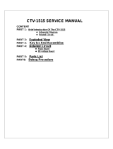
4.1 PLL Reference Clock Solutions
This section describes the clock requirements and a system solution for the PLL
reference clocks. There are two types of PLLs and each type has different requirements
for its reference clocks. The core PLL and DDR PLL produce clocks for digital logic,
whereas the SRIO and SGMII PLLs produce clocks for SERDES (serializer/deserializer)
links. Figure 2 is a functional representation of how the reference clocks are connected
inside the device.
Figure 2 TMS320TCI6484 and TMS320C6457 DSP Reference Clocks
The core PLL can be configured with multiplier values from 1× to 32× and any integer
value in between as long as the PLL output frequency does not violate the maximum
operating frequency for the device. There are minimum core clock frequency
requirements for some peripherals so the data sheet should be consulted to check for
any limitations with the desired core clock frequency. The DDR PLL uses a fixed 10×
multiplier. The SERDES PLL multipliers are covered in the peripherals section.
All differential clock input buffers are LJCBs (Low Jitter Clock Buffers). These input
buffers include a 100-Ω termination (P to N) and a common mode biasing. Because the
common mode biasing is included, the clock source must be AC-coupled. LVDS and
LVPECL clock sources are compatible with the LJCBs.
TCI6484 / C6457
CORECLK(N|P)
ALTCORECLK
CORECLKSEL
PLL1
(CORE)
DDRREFCLK(N|P)
ALTDDRCLK
DDRCLKSEL
PLL2
(DDR)
SRIOSGMIICLK(N|P)
SRIO SerDes
PLL
SGMII SerDes
PLL

Page 8 of 50 TMS320TCI6484 and TMS320C6457 DSPs Hardware Design Guide SPRAAV7B—October 2009
Submit Documentation Feedback
4 Clocking
www.ti.com
Any unused LJCB inputs should be connected to produce a valid logic level. The
recommended connections are shown in Figure 3. The 1-kΩ resistor is to reduce
power.
Figure 3 Unused LJCB Connections
4.1.1 Clock Requirements
The clock requirements are shown in Table 2.
The main concerns for the differential reference clocks are low jitter and proper
termination. Either LVDS or LVPECL clock sources can be used but they require
different terminations. The input buffer sets its own common mode voltage (CML) so
AC coupling is necessary. It also includes a 100-Ω differential termination resistor,
eliminating the need for an external 100-Ω termination when using an LVDS driver.
For generation information on AC termination schemes, see the AC-Coupling Between
Differential LVPECL, LVDS, HSTL, and CML application report.
LJCB_P
DSP
LJCB_N
1k Ohms
1.1V
100 Ohms
Table 2 PLL Reference Clock Requirements
Clock Logic Input Jitter
1
T
rise
and
T
fall
2
Duty Cycle Stability Frequency Range
Max PLL
Frequency
CORECLKP/
CORELKN
LVDS or
LVPECL
100 ps peak-to-peak 50 ps-350 ps 45/55% ± 100 PPM 50 MHz – 61.44 MHz 1.0 GHz
ALTCORECLK 1.8-V LVCMOS 100 ps peak-to-peak 50 ps-350 ps 45/55% ± 100 PPM 50 MHz – 61.44 MHz 1.0 GHz
DDRREFCLKP /
DDRREFCLKN
LVDS or
LVPECL
2.0% of DDRREFCLKP/N input
period (peak-peak)
3
50 ps-350 ps 45/55% ±100 PPM 40 MHz – 66 MHz 333 MHz
ALTDDRCLK 1.8-V LVCMOS 2.0% of DDRREFCLKP/N input
period (peak-peak)
50 ps-350 ps 45/55% ±100 PPM 40 MHz – 66 MHz 333 MHz
RIOSGMIICLKP /
RIOSGMIICLKN
(if SRIO is used)
LVDS or
LVPECL
4ps RMS
56 ps pk-pk @ 1 × 10
-12
BER
50 ps-350 ps 45/55% ±100 PPM 125 MHz, 156.25 MHz,
312.5 MHz
2.5 GHz or
3.125 GHz
RIOSGMIICLKP /
RIOSGMIICLKN
(if SRIO is notused)
LVDS or
LVPECL
8ps RMS
112 ps pk-pk @ 1 × 10
-12
BER
50 ps-350 ps 45/55% ± 100 PPM 125 MHz, 156.25 MHz,
312.5 MHz
2.5 GHz
End of Table 2
1. Peak-to-peak jitter value for DDRREFCLK is measured at 10,000 sample points. Total RMS jitter values for RIOSGMIICLK are specified for a target BER for the associated
SERDES interface.
2. T
rise
/T
fall
values are given for 10% to 90% of the voltage swing.
3. In example assuming a 66 MHz DDRREFCLK the total allowable jitter on the reference clock would be approximately 300ps peak-to-peak

SPRAAV7B—October 2009 TMS320TCI6484 and TMS320C6457 DSPs Hardware Design Guide Page 9 of 50
Submit Documentation Feedback
4 Clocking
www.ti.com
4.1.2 Single Device Solution
It is assumed that the source clock is an oscillator on the same board as the
TMS320TCI6484 and TMS320C6457 DSP device. Use of distributed clocks may
require a jitter cleaner device such as the CDCL6010. If an on-board oscillator is used
with one DSP device, no other components should be needed except for terminations.
Examples of 3.3-V differential oscillators are:
• Pletronics oscillator: LVDS LV77D
• Pletronics oscillator: LVPECL PE77D
These oscillators have not been tested but are examples of oscillators that meet the
specification requirements for all TMS320TCI6484 and TMS320C6457 DSP
differential reference clocks. Note that these oscillators require 3.3 V. No availability of
1.8-V differential oscillators that meet the clocking requirements was found, although
they may exist.
Figure 4 shows an LVDS based solution including terminations.
Figure 4 Differential Single Device LVDS Clock Solution
Note—The receiver is self-biasing and does not require the 10-kΩ pullup and
pulldown shown in the referenced application note.
Figure 5 shows an LVPECL based solution including terminations.
Figure 5 Differential Single Device LVPECL Clock Solution
LOW JITTER
LVDS
OSCILLATOR
CLKP
DSP
CLKN
0.01uF
0.01uF
CLKP
DSP
CLKN
LOW JITTER
LVPECL
OSCILLATOR
150 ohm
150 ohm
0.01uF
0.01uF

Page 10 of 50 TMS320TCI6484 and TMS320C6457 DSPs Hardware Design Guide SPRAAV7B—October 2009
Submit Documentation Feedback
4 Clocking
www.ti.com
4.1.3 Multiple Device Fanout Solutions
For systems with multiple TMS320TCI6484 or TMS320C6457 DSP devices it may be
preferred to use one oscillator and a fanout buffer instead of multiple oscillators. This
would allow for fewer components as well as lower cost. The fanout buffer can increase
the jitter at the clock input so care must be taken in selecting the combination of
oscillator and fanout buffer.
In most cases, the same oscillators described in section 4.1 on page 1-7 can be used for
the fanout case. The oscillator output specifications should be compared to the fanout
buffer input specifications to make sure they are compatible.
If 3.3 V is available, there are many options for clock oscillators and fanout buffers.
There are fewer options for 1.8-V fanout buffers but TI does offer one: the CDCL1810.
For an all 1.8-V solution, a 1.8-V single-ended oscillator can be used with the
CDCL6010. Because the CDCL6010 is a jitter cleaner, the single-ended oscillator does
not need to be low-jitter, which allows it to be lower in cost. Also, if a distributed clock
with jitter exceeding the input jitter specification is the source (either single ended or
differential), the CDCL6010 can be used for both jitter cleaning and distribution. The
solution using the CDCL6010 is described in Section 4.1.3.2.
4.1.3.1 Fanout Solutions (No Jitter Cleaning)
Suggested 3.3-V fanout buffers are:
• TI SN65LVDS108 LVDS 1:8 clock fanout buffer
– TI data sheet SLLS399, SN65LVDS108 8-Port LVDS Repeater
– See Figure 6
Figure 6 Multiple Devices LVDS Clock Solution
LOW JITTER
LVDS
OSCILLATOR
CLKP
SN65LVDS108
CLKN
CLKP
DSP1
CLKN
CLKP
DSP8
CLKN
CLK0
CLK0#
CLKN
CLK7#
100ohms
0.01uF
0.01uF
0.01uF
0.01uF

SPRAAV7B—October 2009 TMS320TCI6484 and TMS320C6457 DSPs Hardware Design Guide Page 11 of 50
Submit Documentation Feedback
4 Clocking
www.ti.com
• TI CDCLVP110 LVPECL 2:10 clock fanout buffer
– TI data sheet SCAS683, CDCLVP110 Low-voltage 1:10 LVPECL/HSTL With
Selectable Input Clock Driver
– See Figure 7.
Figure 7 RIOCLK Multiple Devices LVPECL Clock Solution
There are also 4-port and 16-port versions of the SN65LVDS108.
Texas Instruments also has a 1.8-V fanout buffer that includes some options for
providing divided-down outputs. This is:
• TI CDCL1810 1:10 clock fanout buffer
– New Product: see TI representative for details and availability
– TI data sheet SLLS781, CDCL1810 1.8V, 10 Output, High-Performance Clock
Distributor
– See Figure 8.
Figure 8 Multiple Devices 1.8V LVDS Clock Solution
These buffers have not been tested but are examples of buffers that meet the
specification requirements for all of the DSP differential clock inputs.
LOW JITTER
LVPECL
OSCILLATOR
CDCLVP110
DSP1
DSP10
CLK0
CLK0#
CLKN
CLK9#
50 ohm
50 ohm
50 ohm
150
ohm
150
ohm
150
ohm
150
ohm
0.01uF
0.01uF
0.01uF
0.01uF
CLKP
CLKN
CLKP
CLKN
CLKP
CLKN
LOW JITTER
LVDS
OSCILLATOR
CLKP
CDCL1810
CLKN
CLKP
DSP1
CLKN
CLKP
DSP10
CLKN
CLK0
CLK0#
CLK9
CLK9#
0.01uF
0.01uF
0.01uF
0.01uF

Page 12 of 50 TMS320TCI6484 and TMS320C6457 DSPs Hardware Design Guide SPRAAV7B—October 2009
Submit Documentation Feedback
4 Clocking
www.ti.com
Jitter performance for the SN65LVDS108 is found in its data sheet. For the
CDCLVP110, jitter characteristics can be found in TI application report SCAA068,
Advantage of Using TI’s Lowest Jitter Differential Clock Buffer.
The fanout buffer outputs should not be used to drive additional fanout buffers because
the jitter will accumulate.
4.1.3.2 CDCL6010-Based Solutions (Jitter Cleaning)
The CDCL6010 is a jitter cleaner and 1:10 fanout buffer that is well suited for use with
the TMS320TCI6484 and TMS320C6457 DSPs. It operates from 1.8 V and meets the
jitter requirements for all differential clock inputs on the device. An example of the
connections when using an LVDS signal as the source is shown in Figure 9.
Figure 9 CDCL6010 Solution with LVDS Input
The connection of a single-ended input clock to CDCL6010 is shown in Figure 10. This
source could be a 1.8-V source or, using a voltage divider, a 3.3-V source such as the
CDCE706 or the CDCE906. TI application report SCAA080, CDCx706/x906
Termination and Signal Integrity Guidelines describes the interface between the
CDCE706/CDCE906 and the CDCL6010 in detail.
Figure 10 CDCL6010 with Single-Ended Input
LVDS signal
CLKP
CDCL6010
CLKN
CLKP
DSP1
CLKN
CLKP
DSP10
CLKN
CLK0
CLK0#
CLK9
CLK9#
0.01uF
0.01uF
0.01uF
0.01uF
1.8V single
ended signal
CLKP
CDCL6010
CLKN
CLK0
CLK0#
CLK9
CLK9#

SPRAAV7B—October 2009 TMS320TCI6484 and TMS320C6457 DSPs Hardware Design Guide Page 13 of 50
Submit Documentation Feedback
4 Clocking
www.ti.com
4.1.4 Layout Recommendations (LVDS and LVPECL)
4.1.4.1 Placement
• The oscillator, buffer, and DSPs should be placed as close to each other as
practical.
• Fanout buffers should be placed in a central area to equalize the trace lengths to
each DSP.
• AC coupling capacitors should be placed near the receivers.
• 50-Ω resistors used in LVPECL DC termination should be placed near the
receiver.
• 150-Ω resistors used in LVPECL AC termination should be placed near the
driver.
4.1.4.2 Trace Routing
• A GND plane should be placed below the oscillator.
• Digital signals should not be routed near or under the clock sources.
• Traces should be 100-Ω differential impedance and 50-Ω single-ended
impedance.
• Clock traces should be routed as differential pairs with no more than two vias per
connection (not counting pin escapes).
• The number of vias on each side of a differential pair should match.
• Differential clock traces must be matched in length to within 10 mils.
• Maintain at least 25-mil spacing to other traces.

Page 14 of 50 TMS320TCI6484 and TMS320C6457 DSPs Hardware Design Guide SPRAAV7B—October 2009
Submit Documentation Feedback
4 Clocking
www.ti.com
4.2 Non-PLL Reference Clock Solutions
There are several peripherals that use reference clock inputs for operation. These, and
their clocks, are:
• EMIF64: AECLKIN
• UTOPIA: UXCLK, URCLK
• McBSP: CLKS0, CLKS1
• Timers: TIMI0, TIMI1
Table 3 shows all single-ended clocks with 1.8-V LVCMOS inputs. The specific
requirements for these clocks are also shown in Table 2. Use of standard oscillators and
buffers should be adequate for these clocks with the exception that they do require
1.8-V operation.
There are some 1.8-V LVCMOS oscillators and 1.8-V 1:N clock buffers available,
although the selection is limited. One alternative is to have an oscillator supply multiple
loads of a standard buffer. Typically oscillators are rated to drive 15-pF loads. The TI
AUC buffers are typically rated around 3 pF per input, so an oscillator could drive five
inputs of an AUC part. Because the AUC parts are 3.3-V tolerant, a standard 3.3-V
oscillator could be used. See Figure 11 for one example of a solution.
Figure 11 LVCMOS Clock Buffer
Table 3 Non-PLL Clock Requirements
Clock Logic Input Jitter Duty Cycle Stability Frequency Range
AECLKIN 3.3-V LVCMOS 2.5% of input clock period 40/60% Not specified DC to 100 MHz
UXCLK, URCLK (UTOPIA) 3.3-V LVCMOS 2.5% of input clock period 40/60% Not specified DC to 50 MHz
CLKS0, CLKS1(McBSP) 1.8-V LVCMOS Not specified Not specified Not specified DC to 120 MHz
TIMI0, TIMI1(Timer) 1.8-V LVCMOS Not specified Not specified Not specified DC to 50 MHz
End of Table 3
SN74AUC125
1A
1.8V to 3.3V
OSCILLATOR
10
2A
3A
4A
1Y
2Y
3Y
4Y
CLK
DSP1
CLK
DSP2
CLK
DSP3
CLK
DSP4

SPRAAV7B—October 2009 TMS320TCI6484 and TMS320C6457 DSPs Hardware Design Guide Page 15 of 50
Submit Documentation Feedback
5 Power Supplies
www.ti.com
5 Power Supplies
5.1 Power Plane Generation
All power supplies may be generated from switching supplies. Filters are recommended
for some power supplies. An overview of the recommended power supply generation
architecture is shown in Figure 12. Additional information can be found in the TI
application report SCAA048, Filtering Techniques: Isolating Analog and Digital Power
Supplies in TI’s PLL-Based CDC Devices.
Figure 12 TMS320TCI6484 and TMS320C6457 DSP Power Supplies
Fixed
REGULATOR
1.10 V or 1.20 V
FIXED
REGULATOR
1.8 V
DV
DD18
FIXED
REGULATOR
1.1 V
CV
DD
BOARD VOLTAGE
(i.e. 5 V, 8 V, 9.6 V)
TCI6484 / C6457
VOLTAGE
PLANES
FILTER
FILTER
V
DDA11
V
DDT11
FILTER
FILTER
PLLV
1
PLLV
2
V
DDR18
FILTER
V
DDD11
FIXED
REGULATOR
3.3 V
DV
DD33

Page 16 of 50 TMS320TCI6484 and TMS320C6457 DSPs Hardware Design Guide SPRAAV7B—October 2009
Submit Documentation Feedback
5 Power Supplies
www.ti.com
The recommended EMI filter circuit from Murata is shown in Figure 13. If the
peripheral associated with the power supply is not used, it still needs to be powered but
the filters are not required.
Figure 13 Recommended Power Supply Filter
A reference voltage is needed for the SSTL (DDR2) interface. This can be done through
a simple voltage divider as shown in Figure 14. See Section 5.4 for additional details.
Figure 14 VREFSSTL Reference Voltage
5.2 Power Supply Sequencing
The required power supply sequence is defined by the following steps:
1. DV
DD18
, PLLV
1
, PLLV
2
, and V
DDR18
simultaneously ramp within 5 ms of each
other
2. CV
DD
, DV
DD11
, V
DDA11
, and V
DDT11
simultaneously ramp within 5 ms of each
other
3. DV
DD33
ramps
100 μs after DV
DD33
is stable, the POR signal can be brought high and device execution
can begin.
The delay between steps should be a minimum of 500 μs and a maximum of
200 milliseconds.
See the device data manual for more details.
NFM18CC223R1C3
0.1µF
560pF
FROM POWER
SUPPLY
TO TCI6484 \
C6457
1k 1%
1k 1%
DV
DD18
V
REFSSTL
(DDR2)
0.1µF
0.1µF

SPRAAV7B—October 2009 TMS320TCI6484 and TMS320C6457 DSPs Hardware Design Guide Page 17 of 50
Submit Documentation Feedback
5 Power Supplies
www.ti.com
5.3 Voltage Plane Power Requirements
Power requirements are highly dependent on the usage of the device. This includes core
voltage and operating frequency selected, peripheral utilization and case temperature.
Table 4 shows estimated power numbers for a typical Pico Base Station system. The
example was derived using the Power Consumption Summary application report and
power spreadsheet.
Note—It is recommended that all system designers use the power spreadsheet
to estimate their system power usage prior to designing a power distrubution
system.
Depending on the specific design and usage, the worse-case transient conditions
should be taken into account when evaluating power supplies and associated capacitors
(Section 5.6.1 and Section 5.6.2). Designs outside of the approximate maximum values
should re-examine power supply selection and design layout. These values should not
be used to estimate thermal performance.
5.4 Power Supply Layout Recommendations
Core and I/O supply voltage regulators should be located close to the DSP device (or
device array) to minimize inductance and resistance in the power delivery path. In
addition, when designing for high-performance applications using the
TMS320TCI6484 or TMS320C6457 DSPs platforms, the PCB should include separate
power planes for core, I/O, and ground, all bypassed with high-quality, low-ESL/ESR
capacitors.
For V
REFSSTL
, one reference voltage divider should be used for both the DSPand the
reference voltage input on the DDR-SDRAMs. The VREF resistor divider should be
placed between the two devices and the routes made as directly as possible with a
minimum 20-mil-wide trace. There should be a 2× trace width clearance between the
routing of the reference voltage and any switching signals.
Table 4 Estimated Power Usage for a Typical Pico Base Station System Scenario
1
Power Signal Voltage Estimated Power Usage Peripheral Utilization
2
CV
DD
1.1 V 2309.13 mW • CPU Frequency - 1.0 GHz
• CPU Utilization - 50%
DV
DD33
3.3 V 212.97 mW • EMIFA Frequency - 100 MHz, EMIFA Utilization - 50%, EMIFA Switching - 50%
• HPI Frequency - 50 MHz, HPI Utilization - 30%, HPI Switching - 50%
•UTOPIA - Disabled
DV
DD18
1.8 V 363.93 mW • DDR2 Frequency - 250 MHz, DDR2 Utilization - 60%, DDR2 Switching - 50%
•McBSP0 - Disabled
•McBSP1 - Disabled
• SRIO Mode- 3 x1 lanes at 3.125 Gbps, SRIO Utilization - 15%
•EMAC - Disabled
DV
DD11
1.1 V 377.28 mW • SRIO Mode- 3 x1 lanes at 3.125 Gbps, SRIO Utilization - 15%
•EMAC - Disabled
Total 3263.31 mW
End of Table 4
1. Please see the Power Spreadsheet and Application Report for more details about specific use-conditions and peripheral utilization termonology.
2. Many peripherals, such as SRIO and EMAC are powered from multiple voltage nets so their usage is noted under all applicable supplies

Page 18 of 50 TMS320TCI6484 and TMS320C6457 DSPs Hardware Design Guide SPRAAV7B—October 2009
Submit Documentation Feedback
5 Power Supplies
www.ti.com
5.5 Voltage Tolerances, Noise, and Transients
The voltage tolerances specified in the data manual include all DC tolerances and the
transient response of the power supply. These specify the absolute maximum and
minimum levels that must be maintained at the pins of the DSP device under all
conditions. Special attention to the power supply solution is needed to achieve this level
of performance, especially the 3% tolerance on the core power plane (CV
DD
).
To maintain the 3% tolerance at the pins, the tolerance must be a combination of the
power supply DC output accuracy and the effect of transients. A reasonable goal for the
DC power supply output accuracy is 1.5%, leaving 1.5% for the transients. At a nominal
1.1-V CVDD, 3% tolerance is +/-33 mV. This allows 16.5 mV of DC accuracy from the
output of the power supply and another 16.5 mV due to transients.
5.5.1 Using Remote Sense Power Supplies
Use of a power supply that supports the remote sense capability allows the power
supply to control the voltage at the load. Special layout care must be used to keep this
sense trace from being lost during PCB layout. One solution is placement of a small
resistor at the load and connecting the sense trace to the voltage plane through it. If a
power plane is shared by a group of DSP devices, the sense resistor should be placed at
the center of this group. If a negative sense pin is supported by the voltage regulator, it
should be handled in a similar way. An example of this type of implementation is
shown in Figure 15.
Figure 15 Multiple DSP Remote Sense Connections
TCI6484 /
C6457
#1
DVDD
VSS
TCI6484 /
C6457
#3
VSS
TCI6484 /
C6457
#2
VSS
TCI6484 /
C6457
#4
VSS
+SENSE
VSS
-SENSE
VOUT
0 Ohms
0 Ohms
DVDD
VSS
REGULATOR
Routed as a signal
Routed as a signal
DVDD
VSSVSS
VSS
VSS
DVDD and VSS
routed as planes
DVDD
VSS
DVDD DVDD
DVDD DVDD DVDD DVDD

SPRAAV7B—October 2009 TMS320TCI6484 and TMS320C6457 DSPs Hardware Design Guide Page 19 of 50
Submit Documentation Feedback
5 Power Supplies
www.ti.com
If the connection is between one DSP device and one voltage regulator, there are
voltage monitor pins that can be used for this case (CVDDMON, DVDD18MON, and
DVDD33MON). The monitor pins indicate the voltage on the die and therefore
provide the best remote sense voltage. These monitor pins should be connected directly
to the positive side sense pin of the voltage regulator.
Note—If the monitor pins are not used to monitor the voltage, they should be
connected to their respective power planes (i.e. CVDDMON connects to
CVDD, DVDD18MON connects to DVDD18, and DVDD33MON connects
to DVDD33).
The voltage regulator output could become unstable and drive to a high voltage if the
positive sense line does not receive the correct voltage. Some voltage regulators (i.e. the
TI PTH08T240F) include a low impedance path between the VOUT and +SENSE so
that this would result only in a small drop in performance. If this feature is not present
in the voltage regulator, it is recommended to place a 100-Ω resistor near the DSP
between the voltage plane and the monitor pin.
If the VDD monitor connection to the DSP (i.e. CVDDMON) is not present for some
reason, the positive sense will still regulate to the proper voltage. If a negative sense pin
is provided by the regulator this should be connected to the GND plane near the DSP
using a 0-Ω resistor. The single DSP remote sense connections are shown in Figure 16
for the CVDD plane. The same solution could be used for all/any planes.
Figure 16 Single DSP Remote Sense Connections
5.5.2 Voltage Plane IR Drop
The voltage gradient (IR drop) needs to be considered whether or not a supply with the
remote sense capability is used. The DSPs closer to the supply will have a slightly higher
voltage and the DSPs farther from the supply will have a slightly lower voltage. This
voltage differential can be minimized by making the copper planes thicker or by
spacing the DSPs across a wider area of the plane. Be sure to consider both the core
power plane(s) and the ground plane(s). The resistance of the plane can be determined
by the following formula:
R = rho × length ÷ (width × thickness)
CVDDMON
CVDD
VSS
100 ohms
0 ohms
+SENSE
VSS
-SENSE
VOUT
Routed as a signal
Routed as a signal
REGULATORTCI6484 / C6457
CVDD
CVDD
VSSVSS
CVDD and VSS
routed as planes

Page 20 of 50 TMS320TCI6484 and TMS320C6457 DSPs Hardware Design Guide SPRAAV7B—October 2009
Submit Documentation Feedback
5 Power Supplies
www.ti.com
where rho is the resistivity of copper equal to 1.72
-8
Ω-meters. PCB layer thickness is
normally stated in ounces. One ounce of copper is about 0.012 inches or 30.5
-6
meters
thick. The width must be derated to account for vias and other obstructions. A 50-mm
wide strip of 1-oz copper plane derated 50% for vias will have a resistance of 0.57 mΩ
per inch.
5.6 Power-Supply Decoupling and Bulk Capacitors
In order to properly decouple the supply planes from system noise, decoupling and
bulk capacitors are required.
Considering current technology, 0402-sized capacitors should be used for standard
decouplers where possible. Proper board design and layout should allow for correct
placement of all capacitors (see Table 5 for capacitor recommendations and values).
Generically speaking, bulk capacitors are used to minimize the effects of low frequency
current transients (see Section 5.6.1) and decoupling or bypass capacitors are used to
minimize higher frequency noise (see Section 5.6.2). Proper printed circuit board
design is required to ensure functionality and performance.
One key element to consider during the circuit board (target) design is added lead
inductance or the pad-to-plane length. Attachment for decoupler and bypass
capacitors to the respective power planes should be made (where possible) using
multiple vias in each pad that connects the pad to the respective plane. The inductance
of the via connect can reduce or eliminate the effectiveness of the capacitor so proper
via connections are important. Trace length from the pad to the via should be no more
than 10 mils (0.01 inch) and the width of the trace should be the same width as the pad.
As with selection of any component, verification of capacitor availability over the
product’s production lifetime should be considered. In addition, the effects of the
intended operating environment (temperature, humidity) should also be considered
when selecting the appropriate decoupling and bulk capacitors.
Note—All values and recommendations are based on a single TMS320TCI6484
or TMS320C6457 DSP device and the use of recommended on board power
supply modules, alternate power supplies and decoupling/bulk capacitor
values will require additional evaluation.
A capacitor selection spreadsheet and user application note (TBD) is available to assist
in determining the minimal amount of bulk and decoupling capacitance required (for
use with the PTH08T240Fxx module only)
/