Aquatic 6030BFSC Operating instructions

Category
Wall & ceiling mounts accessories
Type
Operating instructions
Aquatic 8101 E. Kaiser Blvd. Anaheim, CA 92808 (800) 877-2005 FAX (714) 998-5340 www.aquaticbath.com
— 1
Installation Instructions
Accessible Acrylic Showers and Tub/Showers
Fax on Demand # 1364
Aquatic products may be specified as Lasco Bathware.
PRE-INSTALLATION PLANNING
1. Unit must be placed within bathroom area before completion of door framing or, if preferred, studs may be omitted or knocked-
out to permit unit placement.
2. Review job print and Aquatic rough-in dimensions; verify all key dimensions against actual job conditions .
3. Make sure framed-in alcove is of proper size, square and plumb; check floor for levelness.
4. If fire-rated alcove is required, approved finish material must be in place prior to unit installation to meet fire safety requirements
of local building code and/or FHA/HUD Minimum Property Standards. NOTE: Finished alcove must have interior dimensions
shown on rough-in diagram to permit installation of unit.
5. Foundation materials (industrial plaster, mortar mix, lightweight grout) are mandatory under the bottom of each unit to solidify
for wheelchair support.
6. If dome light will be installed, cut out required area within molded 12” (305mm) sq. flat area in center of dome. Use fine-tooth
or abrasive-grit blade. Cut from inside. Light fixture must have UL label and be water and steam tight.
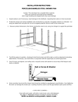
7. For showers, provide a 6” x 6” (150mm x 150mm) floor opening for 2” (50mm) IPS and below grade drain connection. (Fig. 1)
For tub/showers, provide a 6” x 12” (150mm x 305mm) floor opening for 1
1
2
” (40mm) O.D. plumbing drain and overflow kit.
Note: Confirm if right or left hand tub drain. (Fig. 2)
8. Front corner posts are double 2 x 4 studs for flush mounting or triple 2 x 4 studs for recessed mounting. (Fig. 3)
9. 1 x 2 mounting plates installed on front corner posts and on front header. (Fig. 1 Showers, Fig. 2 Tub-Showers)
10. To avoid obstruction, make sure that supply lines and valve plumbing are not strapped to studs and do not project into alcove.
Also, drain pipe must not project above floor level prior to installation.
11. On inside of plumbing wet wall of unit, note location of supply vacuum breaker and mixer valve.
12. Double check location of plumbing to ensure proper fit of all plumbing to the mixing valve and supply elbow.
13. Fasten drain fitting to unit before installing (see manufacturer’s instructions).
ADA/ANSI COMPLIANT BARRIER-FREE SHOWER STALLS:
For roll-in showers with a flat threshold, build up or recess the bathroom floor
3
4
less the thickness of the finished floor. For
beveled thresholds, build up or recess the bathroom floor
3
4
less the thickness of the finished floor, ensuring that the finished
floor meets the base of the bevel at the threshold.
It is recommended that the bathroom floor outside ADA clear floor space be designed with a floor drain to alleviate any
water over spray that may escape the shower stall.
ADA Code from the Federal Register Department of Justice 28CFR Part 36 section 4.21.7, July 1, 1994 Rules & Regulations. Excerpt from Paragraph
4.21.7 Curbs “Shower stalls that are 30” x 60” minimum shall not have curbs.”
ADA Code from the Federal Register Federal Access Board, July 24, 2004. Paragraph 608.7 Thresholds. Thresholds in roll-in type shower compartments
shall be
1
2
” (15 mm) high maximum in accordance with 303. In transfer type shower compartments, thresholds
1
2
” (15 mm) high maximum shall be
beveled, rounded, or vertical.
EXCEPTION: A threshold 2” (50 mm) high maximum shall be permitted in transfer type shower compartments in
pre-existing facilities where provision of a
1
2
” (15 mm) high threshold would disturb the structural reinforcement of the floor slab.
Aquatic 8101 E. Kaiser Blvd. Anaheim, CA 92808 (800) 877-2005 FAX (714) 998-5340 www.aquaticbath.com
— 2
Installation Instructions
Accessible Acrylic Showers and Tub/Showers
Fax on Demand # 1364
Aquatic products may be specified as Lasco Bathware.
INSTALLATION PROCEDURE
1.
Before placing unit in framed alcove, spread a bed of foundation material around drain extending to perimeter
of shower floor (drain box-out should be back-filled with foundation material).
2. Lift and place unit directly on top with drain fitting over and onto waste pipe with threshold firmly on the floor. Assure
waste pipe protrudes well into drain fitting. Maintain proper floor slope towards drain.
3. Level unit for proper drainage using a 3’ (910mm) long level on top of dam and on front face.
4. Using holes provided, screw (do not nail) unit to mounting places. Start at holes at lower left and right, proceeding upward
alternately on each side and across the top. For wood framework, use #8 x 1
1
2
” (40mm) flathead wood screws. For metal
framework, use #12 x 1” (25mm) sheet metal screws. Drive screws snugly but do not overtighten.
CAUTION: Do not nail into face of mounting flange. Do not strike flange with any tool.
5. Reference instructions for building up or floating sub-floor for barrier-free installation. (See Page 1.)
6. Note fitting locations and make final connections of vacuum breaker and hose to supply elbow, and escutcheon plate and knob
to mixer valve. NOTE: When caulking drain, protect gelcoat surfaces with corrugated paper. Strap water lines, supply elbow
and mixer valve to studs.
7. Finish front of the unit with drywall. (Fig. 3)
Threshold Center Hold-Down (For models with skirt higher than 3/4”)
Fig. 4a Concrete floor installation: Fig. 4b Wood floor installation:
Fig. 2 Framing: Tub/Showers
Height
1" x 2"
(25 x 50)
Plates
Width
6" x 12"
(150mm x 305mm)
Box-Out
See Fig. 3
INSTALL SOFFIT, HEADER AND
TOP PLATE AFTER UNIT IS IN PLACE
Depth
Rough Center
Rough Center
Height
1" x 2"
(25 x 50)
Plates
Depth
Rough
Center
Width
See Fig. 3
INSTALL SOFFIT, HEADER
AND TOP PLATE AFTER UNIT
IS IN PLACE
6" x 6”
(150mm x 150mm)
Box-Out
D
Fig. 1 Framing: Showers
2" x 4" (50x100) 2" x 4" (50x100)
1" x 2" (25x50)
Plate
1" x 2" (25x50)
Plate
Drywall
Finished Edge
Drywall
Finished Edge
³⁄₈" (10)
³⁄₈" (10)
¹⁄₂" to ⁵⁄₈" (15)
Drywall
⁵⁄₈" (15)
Drywall to
assure coverage
of Mounting
Screws
Fig. 3 Finishing
A
FASTEN TO UNIT WITH
DRYWALL SCREW
AQUATIC UNIT
FLOOR
FASTEN DOWN TO FLOOR
WITH DRYWALL SCREW
OR CONCRETE NAIL
DETAIL A
SCALE 1 : 2
3/4"
1"
1/8" PILOT HOLE
AQUATIC UNIT
FLOOR
DETAIL A
SCALE 1 : 2
FASTEN DOWN TO FLOOR
AT C OF UNIT WITH DRYWALL
SCREW
L
A
Drill
1
8
” pilot hole and
screw with drywall screw
to hold down the center of threshold
to prevent moving during installation.
Use 90° angle bracket,
approxi mately
1
2
” x
1
2
” x 1
1
2
in size with pre-drilled holes
to hold down the center of threshold
to prevent moving during installation.
Aquatic 8101 E. Kaiser Blvd. Anaheim, CA 92808 (800) 877-2005 FAX (714) 998-5340 www.aquaticbath.com
— 3
Installation Instructions
Accessible Acrylic Showers and Tub/Showers
Fax on Demand # 1364
Aquatic products may be specified as Lasco Bathware.
CLEAN-UP
1. Do not remove warranty/maintenance adhered label. Leave on unit for owner/occupant per code requirement.
2. Prevent staining. Remove all debris before plumbing leak test. Use sponge with warm water and liquid detergent. Rinse,
drain and wipe clean. Do not use abrasive cleansers such as scouring powders, steel wool, metal scrapers, sand paper or
anything else that might mar, dull or scratch the finish.
3. Plaster and latex paint may be removed with warm water, liquid detergent and brittle brush or plastic scraper. Glues, tars and
enamels may be removed with acetone or paint thinner. Do not use turpentine or laquer thinner. Do not use excessive heat
or any caustic solvents or chemicals.
4. Dull areas and light scratches may be removed by buffing with a light colored automotive rubbing compound and buffing pad.
Entire unit can be waxed with light colored automotive wax. Do not wax bottom of unit.
5. See user maintenance label for more details.
OPTIONAL VINYL FLEXIBLE DAM (Model #: 9STRIP)
NOTE: Please check with your local Building Code Authority for final code approval.
Installation
1. Make sure the vinyl flexible dam is of proper length by measuring right to left, in between shower walls.
2. Round all four bottom corners to approximately a
3
8
” radius with a sander or utility knife to fit.
3. Before installing, wipe the top of shower threshold with a 50:50 mixture of
isopropyl alcohol and water until surface is clean. Wipe dry.
IMPORTANT: To obtain maximum adhesion, the threshold must be clean and
completely dry before applying vinyl dam.
4. Beginning from one end, place the vinyl dam on top of the shower threshold,
peel away adhesive and press down towards other end.
5. Apply pressure (at least 15 psi) at the bond line. Firm application pressure
facilitates stronger adhesion.
6. Silicone both inside and outside the entire length of the vinyl dam with clear or
white sealant.
7. Product needs to set for 72 hours to acquire 100% bond.
Maintenance
Clean with mild detergent and warm water or any non-abrasive, non-petroleum based cleaner.
Use of harsh chemicals, petroleum based or abrasive cleaners will damage product.
Fig. 5
Installation Instructions
Accessible Acrylic Showers and Tub/Showers
Fax on Demand # 1364
1521 No. Cooper, Ste. 500
Arlington, TX 76011
PH: 800-945-2726, 817-801-8300
FAX: 866-544-5353
Customer Service | Technical Services | Warranty Services
LITID1364
Aquatic products may be specified as Lasco Bathware.
Installation
1. Make sure threshold is of proper length by measuring right to left, in between columns.
2. Round all four bottom corners on both cap and catch to approx.
3
8
” radius with sander or file to fit.
3. Place catch on top of shower threshold and drill three pilot holes for #8 or #10 self-tapping screws.
4. Clean bottom of catch; then apply
1
4
” bead of silicone sealant to bottom of catch reveal.
5. Replace catch on top of threshold, line up pilot holes and screw down.
6. Snap cap over catch and silicone both inside corner ends and entire inside length of threshold.
Tool silicone with finger and wet rag.
Maintenance
Clean with mild detergent and warm water or any non-abrasive, non-petroleum based cleaner. Use of harsh chemicals,
petroleum based or abrasive cleaners will damage product and may void warranty.
Warranty
Aquatic Removable Threshold assembly has a limited lifetime warranty to the original homeowner against failure resulting from
defects in its manufacture. The replacement of parts is limited to supplying parts and does not include any associated costs.
Improper use of cleaning agents other than those suggested by the manufacturer will void this warranty. Aquatic Removable
Threshold assembly for commercial use has a three year limited warranty. Please contact Aquatic for complete warranty
information .
Cap
Silicone
Screws
Catch
Silicone
Fig. 6
OPTIONAL REMOVABLE THRESHOLD (Model #: 9THRESHOLD)
Fits all barrier-free showers.
Patent Pending
Cap
Aquatic Unit
Catch
Fig. 7
  • Page 1 1
  • Page 2 2
  • Page 3 3
  • Page 4 4

Aquatic 6030BFSC Operating instructions

Category
Wall & ceiling mounts accessories
Type
Operating instructions

Ask a question and I''ll find the answer in the document

Finding information in a document is now easier with AI