Page is loading ...

Controller PC Power SuPPly
remove and rePlaCe ProCedure Guide
(model Ft7000)
tdn 07100-00104 09/2008
CorPorate HeadquarterS:
522 E. Railroad Street
Long Beach, MS 39560
Phone: (228) 868-1317
Fax: (228) 868-0437
COPYRIGHT NOTICE
© 2008 Delaware Capital Formation, Inc. All Rights Reserved. Triton Systems of Delaware,
Inc. is an operating company of Dover Electronics, Inc., a subsidiary of Dover Corporation
(NYSE-DOV). DOVER, the DOVER logo and the Dover family of marks and TRITON, the
TRITON logo and the Triton family of marks are registered trademarks of Delaware Capital
Formation, Inc., a wholly owned subsidiary of Dover Corporation.

2
Ft7000 Controller PC Power SuPPly remove and rePlaCement ProCedureS
IntroductIon .......................................................................................................... 3
Safety .....................................................................................................................3
toolS requIred .......................................................................................................3
r
emoval of the ft7000 controller Pc ...................................................................4
SHut down tHe Ft7000 Controller PC ...................................................................... 4
d
iSConneCt tHe CableS From tHe Ft7000 Controller PC .............................................. 4
remove tHe Ft7000 Controller PC From tHe Control bay ........................................... 5
r
emoval of the ft7000 controller Pc Power SuPPly (IncludeS cd-rom drIve) ..........5
InStallIng the ft7000 controller Pc Power SuPPly ................................................... 7
I
nStallIng the ft7000 controller Pc cd-rom drIve ............................................... 7
I
nStallatIon of the ft7000 controller Pc ............................................................8
SeCurinG tHe Ft7000 Controller PC CaSe ................................................................. 8
i
nStallinG tHe Ft7000 Controller PC in tHe Control bay ............................................ 8
C
onneCtinG tHe CableS to tHe Ft7000 Controller PC ................................................. 9
SyStem Start uP and oPeratIonal teStIng of the ft7000 controller Pc ...............10
S
yStem Start uP ..................................................................................................10
r
eStore ConFiGuration Parameter File ......................................................................10
oPerational teStinG oF tHe Ft7000 .........................................................................10
TABLE OF CONTENTS

3
Ft7000 Controller PC Power SuPPly remove and rePlaCement ProCedureS
INTRODUCTION
This guide details the steps to safely remove and replace the Power Supply as a separate, internal
component of the FT7000 Controller PC Assembly. It includes the necessary steps to remove and
replace the Controller PC from the FT7000 terminal.
TOOLS REQUIRED
SAFETY
Observe all standard safety practices, as they apply to High Voltage and Electrostatic discharge.
**IMPORTANT**
As part of the FT7000 Controller PC Power Supply remove and replace
process, steps have been added that direct the technician to copy the
conguration Parameter le from the terminal to an external USB device
(e.g. thumb drive, memory stick, etc.). Short of a catastrophic failure
of the Controller PC power supply (complete loss of power to the main-
board and/or hard drive), it may be possible, and highly recommended
that the technician make a copy of the conguration Parameter le as a
precautionary step BEFORE servicing the FT7000. Failure to do so may
require extensive re-conguration of the terminal.
If the controller PC Power SuPPly IS beIng rePlaced for a cataStroPhIc
faIlure and the controller PC haS Shut down, Start at the “dISconnect
the cableS from the Ft7000 controller PC” Procedure on Page 4.
Standard electromechanical technicians tool kit, including:
Anti-static wrist strap
USB Thumb Drive (or comparable device)
6” long #1 Phillips Screwdriver
6” long 1/4” at tip screwdriver
In addition:
Key for the security lock of the terminal
New FT7000 Power Supply
FT7000 User and Service Manuals
•
•
•
•
•
•
•
The following procedure musT be performed by a qualified (fT7000-Trained) Technician!

4
Ft7000 Controller PC Power SuPPly remove and rePlaCement ProCedureS
removal of the ft7000 controller Pc aSSembly
IF THE FT7000 CONTROLLER PC IS OFF DUE TO AN INTERNAL POWER SUPPLY FAILURE, START AT
THE “
diSConneCt tHe CableS From tHe Ft7000 Controller PC” PROCEDURE.
SHut down tHe Ft7000 Controller PC
1. Press Ctrl + 1 on the Rear Service Panel (RSP) keyboard and log into Management Functions.
2. Install a USB external storage device (e.g. thumb drive or memory stick) into one of the Controller
PC’s USB ports.
4. Select Option 8,
Terminal Status.
5. Select Option 1, Display Conguration Summary. Save the summary to the USB storage de-
vice.
6. Select Option 2,
Save Parameters to External Storage. Make sure a USB external storage
device (e.g. thumb drive or memory stick) has been installed at one of the Controller PC’s USB
ports.
7. Select Option 5,
System Parameters.
8. Select Option 3,
Shutdown Terminal.
9. Select Option 1 to answer
Yes, Shutdown Terminal.
10. Switch off the UPS.
diSConneCt tHe CableS From tHe Ft7000 Controller PC
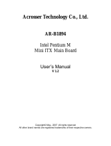
1. Refer to the Figure below. Disconnect the following cables from the rear of the Controller PC As-
sembly:
a. AC line cord
b. Rear Service Panel (RSP) mouse and keyboard cables
c. LAN Ethernet cable
d. GPIO USB cables (Controller PC to UCV GPIO Board and Controller PC to Control Panel GPIO
Board)
e. UPS USB cable (Controller PC to UPS)
f. Audio cable (Line Out)
g. LVDS1 (Rear Display*) and LVDS2 (Control Panel Display*) *It may help to mark the cable.
•
Rear view of Controller PC Assembly. Cables must be disconnected BEFORE removing it from the ATM!
Audio Cable
(Line Out)
AC line cord
RSP Mouse
LAN cable
USB Controller PC to UCV GPIO Board
and Controller PC to Control Panel
GPIO Board cables)
USB Controller PC to
UPS interface cable
LVDS1 (Rear Display)
LVDS2 (Front Display)
RSP Keyboard

5
Ft7000 Controller PC Power SuPPly remove and rePlaCement ProCedureS
remove tHe Ft7000 Controller PC From tHe Control bay
Refer to the Figures below. If installed, loosen the two (2) thumbscrews and remove the retainer
bracket (yellow) on the top right side of the cabinet.
Make sure all cables are clear and that the top right access door is open all the way. Grasp the U-shaped
handle at the top middle of the Controller PC and slowly pull it away from the top shelf in the Control
Bay. Support the bottom of the Controller PC with the other hand, keeping it level until it is clear of the
cabinet.
1.
2.
Location of yellow retaining bracket.
Removing the Controller PC.
removal of the ft7000 controller Pc Power SuPPly (IncludeS the cd-rom drIve)
Procedure:
Place the anti-static wrist strap on your wrist. Attach the grounding wire to a metal part of the
Controller PC case.
Place the Controller PC assembly on a clean, stable and static free work surface.
Refer to Figures below. Remove the two (2) small screws from the top cover front left and right
corners.
Slide the top cover forward until it stops (approximately ¼”).
Lift the front edge of the top cover and pull it away from the Controller PC case.
1.
2.
3.
4.
5.
Remove the two screws (highlighted) from
the Controller PC cover.
Removing the cover from the Controller PC
assembly.

6
Ft7000 Controller PC Power SuPPly remove and rePlaCement ProCedureS
Refer to the Figures below. The power supply is located at the front left corner of the Controller PC
case, underneath the CD-ROM Drive.
Refer to the Figures below. Disconnect the data and power cables from the CD-ROM drive.
Remove the two (2) screws that secure the CD-ROM bracket to the bottom of the Controller PC case
(between the power supply and the hard drive bracket).
Remove the two (2) screws that secure the CD-ROM drive to the front of the Controller PC case,
just above the power supply fan.
Carefully slide the bracket back until the CD-ROM drive clears the front of the Controller PC case.
Lift the bracket with the CD-ROM drive attached out of the Controller PC case.
6.
7.
8.
9.
10.
11.
Location of the CD-ROM Drive in the
Controller PC case.
CD-ROM
Drive
Power
Supply
Location of the Power Supply under the
CD-ROM Drive.
CD-ROM
Drive
Location to the CD-ROM data and power
cables and the mounting screws that se-
cure the CD-ROM bracket to the bottom
of the case.
Data
cable
Approximate locations of the screws that
secure the CD-ROM bracket to the bottom
of the Controller PC case.
Power
cable
The location of the two (2) screws that
secure the CD-ROM bracket to the front
of the Controller PC case.
Mounting screws
for the CD-ROM
Drive bracket.
**CAUTION**
Use extreme caution when handling stat-
ic sensitive electronic devices. Be careful
not to damage the CD-ROM drive when
removing it from the Controller PC case.

7
Ft7000 Controller PC Power SuPPly remove and rePlaCement ProCedureS
Refer to the Figures below. Disconnect power leads to the hard drive, cabinet fans and the moth-
erboard (it may be necessary to cut some cable harness tie wraps).
Remove the four (4) small power supply mounting screws from the face of the Controller PC case.
They are located at the four (4) corners surrounding the fan and AC connector.
Make sure all cables are clear.
Slide the power supply back enough to clear the case and then lift it out.
InStallIng the ft7000 controller Pc Power SuPPly
Procedure:
Refer to the Figures above. Set the power supply down in front left corner of the case, just behind
the front panel.
Slide the power supply up against the inside face of the front panel. Secure the four (4) mounting
screws from the front side of the case.
Connect the power leads to the hard drive, cabinet fans and the motherboard.
InStallIng the ft7000 controller Pc cd-rom drIve
Procedure:
Refer To the Figures on the previous page. Carefully place the bracket with the attached CD ROM
drive in the Controller PC case, above the power supply, just behind the front panel.
Slide the bracket forward until it is ush with the front panel.
Secure the bracket to the front of the Controller PC case with the two (2) mounting screws.
Secure the bracket to the bottom of the Controller PC case with the two (2) mounting screws.
Reconnect the power and data cables to the CD-ROM drive.
Tie wrap the power cables for the CD-ROM drive, hard drive, cabinet fans and the motherboard
together.
12.
13.
14.
15.
1.
2.
3.
1.
2.
3.
4.
5.
6.
A view of the power supply
module after the CD-ROM
drive has been removed.
Location of the four (4) mounting screws for the power
supply assembly on the Controller PC case.

8
Ft7000 Controller PC Power SuPPly remove and rePlaCement ProCedureS
InStallatIon of the ft7000 controller Pc aSSembly
Securing the FT7000 Controller PC case
Refer to the Figures below. Place the top cover on the case, overlapping the front edge approxi-
mately 1/4”. Make sure both L-shaped tabs on both sides of the top cover t into the corresponding
slots on the Controller PC case. Push the top cover backward until it stops (approximately 1/4”).
Make sure the tabs along the back edge of the top cover t under the back edge of the Controller
PC case.
Screw down the top cover at the front left and right corners.
Installing the FT7000 Controller PC in the Control Bay
1. Refer to the Figure below. Make sure all cables are clear and that the top right access panel is open
all the way. Grasp the U-shaped handle at the top middle of the Controller PC. Hold the Controller PC
level with the top shelf in the Control Bay. Place it on the front edge and slide it all the way back.
1.
2.
Secure the two (2) cover mounting screws
(highlighted) on the Controller PC cover.
Placing the cover on the Controller PC as-
sembly.
Installing the Controller PC.

9
Ft7000 Controller PC Power SuPPly remove and rePlaCement ProCedureS
Connecting the Cables to the FT7000 Controller PC
1. Refer to the Figure below. Connect the following cables to the Controller PC:
a. AC line cord
b. Rear Service Panel (RSP) mouse and keyboard cables
c. LAN cable
d. GPIO USB cables (Controller PC to UCV GPIO Board and Controller PC to Control Panel GPIO
Board)
e. UPS USB cable (Controller PC to UPS) to any USB port
f. Audio cable (Line Out)
g. LVDS1 (Rear Display) and LVDS2 (Control Panel Display - It may be necessary to plug in LDVS2
before pushing the Controller PC to the back of the shelf)
2. Refer to the Figure to the right. If used, install the retainer
bracket (yellow) on the top right side of the cabinet. Hand-
tighten the two (2) thumbscrews.
Rear view of Controller PC Assembly, identifying the cables that must be reconnected AFTER placing it on
the top shelf of the FT7000 Control Bay.
Audio Cable
(Line Out)
AC line cord
RSP Mouse
LAN cable
USB Controller PC to UCV GPIO Board
and Controller PC to Control Panel
GPIO Board cables)
USB Controller PC to
UPS interface cable
LVDS1 (Rear Display)
LVDS2 (Front Display)
RSP Keyboard
Location of yellow retaining bracket.

10
Ft7000 Controller PC Power SuPPly remove and rePlaCement ProCedureS
SyStem Start uP and oPeratIonal teStIng of the ft7000 Pc controller
System Start UP
Switch “On” the UPS and Power Supply to power up the terminal.
After Windows, Prism, and Kalignite load, select Option 1, Management Functions from the Pow-
er Up ATM Startup Options menu (or press Ctrl + 1 on the Rear Service Panel (RSP) keyboard).
Log into Management Functions.
IF THE CONFIGURATION PARAMETER FILE WAS NOT PREVIOUSLY “SAVED” DUE TO AN INTERNAL
CONTROLLER PC POWER SUPPLY FAILURE, PROCEED TO THE “oPerational teStinG oF tHe Ft7000”
PROCEDURE.
Restore Conguration Parameter File
Select Option 1, Display Conguration Summary and then print and verify all conguration
parameters with the previously “saved” copy. If it is necessary to restore the “saved” copy of the
conguration parameter le, move on to the next step, otherwise proceed to “Operational Testing
of the FT7000”.
Select Option 8, Terminal Status.
Select Option 3, Restore Parameters from External Storage. Make sure the USB external
storage device with the Saved Parameters has been installed at one of the Controller PC’s USB
ports.
Select Option 1, Display Conguration Summary and then print and verify all conguration pa-
rameters with the previously “saved” copy.
Operational Testing Of the FT7000
Select Option 2, Diagnostics. Run all diagnostic menu selections. Verify no error conditions ex-
ist.
Press the Ctrl key on the Rear Service Panel (RSP) keyboard and select Option 2, Exit Manage-
ment Functions to run Health Check and enter Customer Transactions.
Perform a complete online performance test from Customer Transactions.
1.
2.
3.
•
1.
2.
3.
4.
1.
2.
3.
**IMPORTANT**
As part of the FT7000 PC Power Supply Remove and Replace process, the steps
below direct the technician to copy the previously “Saved” conguration Param-
eter le from the external USB device (e.g. thumb drive) to the terminal. It may not
be necessary to copy this le back to the terminal unless the original was lost or
corrupted while servicing the FT7000.
/