Page is loading ...

Controller PC Hard drive
remove and rePlaCe ProCedure Guide
(model Ft7000)
TDN 07103-00195 08/2008
CorPorate Headquarters:
522 E. Railroad Street
Long Beach, MS 39560
Phone: (228) 868-1317
Fax: (228) 868-0437
COPYRIGHT NOTICE
© 2008 Triton. All Rights Reserved. TRITON logo is a registered trademark of Triton Systems of Delaware.

2
Ft7000 Controller PC Hard drive remove and rePlaCement ProCedures
introduCtion .................................................................................................................... 3
saFety ..................................................................................................................................3
tools required ..................................................................................................................3
Preliminary requirements ................................................................................................3
removal oF tHe Ft7000 Controller PC ........................................................................4
Shutdown and diSconnecting the cableS from the ft7000 controller Pc .............................4
removing the ft7000 controller Pc from the control bay ......................................................5
removinG tHe Ft7000 Controller PC Hard drive and BraCket ................................5
installinG tHe Ft7000 Controller PC Hard drive and BraCket ...............................7
installation oF tHe Ft7000 Controller PC ..................................................................9
inStalling the ft7000 controller Pc in the control bay ..........................................................9
connecting the cableS to the ft7000 controller Pc ...............................................................9
SyStem Start uP and oPerational teSting of the ft7000 controller Pc ...............................10
TABLE OF CONTENTS

3
Ft7000 Controller PC Hard drive remove and rePlaCement ProCedures
INTRODUCTION
This guide details the steps to safely remove and replace the Hard Drive as a separate, internal com-
ponent of the FT7000 Controller PC Assembly. It includes the necessary steps to remove and replace
the Controller PC from the FT7000 terminal.
TOOLS REQUIRED
• FT7000 User Manual and Service Manuals
• Anti-static wrist strap
• USB Thumb Drive
• Small cross point screw driver
• Number 1 or 2 cross point screw driver
• Smallattipscrewdriver
• Key for the security lock of the terminal
• New FT7000 Hard Drive
Thefollowingproceduresmustbeperformedbyaqualied(trained)technician.
SAFETY
Observe all standard safety practices, as they apply to High Voltage and Electrostatic discharge.
PRELIMINARY REQUIREMENTS
1. Press Cntrl + 1 on the RSP keyboard and log into Management Functions.
2.InstallaUSBexternalstoragedevice(i.e.thumbdrive)intooneoftheControllerPC’sUSBports.
3. Select Option 8, Terminal Status.
4. Select Option 1, Display Conguration Summary. Save the summary to the USB storage de-
vice.
5. Select Option 2, Save Parameters to External Storage. Save the parameters to the USB storage
device.
6. Select Option 5, System Parameters.
7. Select Option 3, Shutdown Terminal.
8. Select Option 1 to answer Yes, Shutdown Terminal.
9. Switch off the Power Supply.
**IMPORTANT**
Prior to performing the remove and replace procedures, it is imperative that the
technician use a USB thumb drive to copy the configuration Parameter les of the
terminal. Failure to do so will require extensive re-conguration of the terminal
upon completion of the Hard Drive Replacement.

4
Ft7000 Controller PC Hard drive remove and rePlaCement ProCedures
Removal of the ft7000 ContRolleR PC assembly
Shutdown and diSconnecting the cableS from the ft7000 controller Pc
1. Press Cntrl + 1 on the RSP keyboard and log into Management Functions.
2.InstallaUSBexternalstoragedevice(i.e.thumbdrive)intooneoftheControllerPC’sUSBports.
4. Select Option 8, Terminal Status.
5. Select Option 1, Display Conguration Summary. Save
the summary to the USB storage device.
6. Select Option 2, Save Parameters to External Stor-
age. Make sure a USB external storage device has been
installedatoneoftheControllerPC’sUSBports.
7. Select Option 5, System Parameters.
8. Select Option 3, Shutdown Terminal.
9. Select Option 1 to answer Yes, Shutdown Terminal.
10. Switch off the Power Supply and UPS.
11.RefertoFigure1.Ifinstalled,loosenthetwo(2)thumb-
screwsandremovetheretainerbracket(yellow)onthe
top right side of the cabinet.
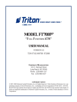
12. Refer to Figure 2. Disconnect the following cable from the rear of the Controller PC Assembly:
a. The AC line cord,
b. The RSP mouse and keyboard,
c. The LAN cable,
d. The2offwhiteUSBcables(ControllerPCtoUCVMainBoardandControllerPCtoControlPanel
DockingBoard),
e. TheblackUSBcable(ControllerPCtoUPS),
f. Theblackaudiocable(LineOut),
g. LVDS1(RearDisplay)andLVDS2(ControlPanelDisplay).
Figure 1. The location of the yellow retain-
ing bracket.
Figure 2. Rear view of Controller PC Assembly identifying the cables that must be disconnected
before removing it from the ATM.
Audio Cable
(LineOut)
AC line cord
RSP Mouse
LAN cable
USB Controller PC to UCV GPIO Board
and Controller PC to Control Panel
DockingBoardcables)
USB Controller PC to
UPS interface cable
LVDS1(RearDisplay)
LVDS2(FrontDisplay)
RSP Mouse

5
Ft7000 Controller PC Hard drive remove and rePlaCement ProCedures
removing the ft7000 controller Pc from the control bay
1. Refer to Figure 3. Make sure all cables are clear and that the top right access panel is open all the way.
Grasp the U-shaped handle at the top middle of the Controller PC and slowly pull it away from the top
shelf in the Control Bay Support the bottom of the Controller PC with the other hand, keeping it level
until it is clear of the cabinet.
Figure 3. Removing the Controller PC.
Removing the ft7000 ContRolleR haRd dRive and bRaCket
Procedure:
1. Place the anti-static wrist strap on your wrist. Attach the grounding wire to a metal part of the
Controller PC case.
3. Place the Controller PC assembly on a clean, stable and static free work surface.
4. RefertoFigure4.Removethetwo(2)smallscrewsfromthetopcoverfrontleftandrightcor-
ners.
5. Slidethetopcoverforwarduntilitstops(approximately¼”).
6. Refer to Figure 5. Lift the front edge of the top cover and pull it away from the Controller PC
case.
Figure 4. Remove the two screws (high-
lighted)fromtheControllerPCcover.
Figure 5. Removing the cover from the
Controller PC assembly.

6
Ft7000 Controller PC Hard drive remove and rePlaCement ProCedures
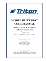
7. Refer to Figure 6. The hard drive is located at the back left corner of the Controller PC case.
8. Refer to Figure 7. Carefully unplug the power and data cables along the right side of the hard
drive.
9. RefertoFigure8.Removethefour(4)screwsontherearofthecase(farthestawayfromthefan)
to free the hard dive bracket.
10. Refer to Figure 9. Lift the bracket and hard drive from the Controller PC case.
**CAUTION**
Use extreme caution when handling static sensitive elec-
tronic devices.
Figure 6. Hard Drive location.
Hard
Drive
D a t a
Cable
Figure 7. HDD Data and Power cables.
P o w e r
Cable
Figure 8. View of the Controller PC assem-
blyidentifyingthefour(4)screwsthatre-
moved in order to take out the hard drive
assembly and bracket.
Figure 9. Removing the hard drive and
mounting bracket from the Controller
PC assembly.

7
Ft7000 Controller PC Hard drive remove and rePlaCement ProCedures
11. Refer to Figures 10 and 11. Place the hard drive and bracket upside down on a clean static free
work surface with the 2 thumbscrews facing forward.
12.Loosenthetwo(2)thumbscrewsonthetophalfoftheharddriveretainerbracket(nowonthebot-
tom).
13.RefertoFigure11.Pullthebottomhalfofthebracket(nowontop)upasfarasitwillgo(approxi-
mately.2”).
14. Carefully remove the hard drive from the retainer bracket.
installing the ft7000 ContRolleR PC haRd dRive and bRaCket
Procedure:
1. RefertoFigures10and11.Placetheharddrivebracketupsidedownwiththetwo(2)thumbscrews
facing forward.
2. Loosenthetwo(2)thumbscrewsonthetophalfoftheharddriveretainerbracket(nowonthebot-
tom).
3. RefertoFigure11.Pullthebottomhalfofthebracket(nowontop)upasfarasitwillgo(approxi-
mately.2”).
4. Carefully slip the hard drive into the top half of the hard drive retainer bracket, the top side down
and the connectors facing right.
**CAUTION**
Use extreme caution: Do not damage the hard drive! Make
sureit’sclearofthelockingangeswhenremovingitfrom
the bracket.
Figure 10. Hard drive and mounting brack-
et removed from the Controller PC.
Figure 11. Removing the hard drive from
the mounting bracket.
**CAUTION**
Use extreme caution when handling static sensitive elec-
tronic devices.
**CAUTION**
Use extreme caution: Do not damage the hard drive! Make
sureit’sclearofthelockingangeswhenmountingitinthe
bracket.

8
Ft7000 Controller PC Hard drive remove and rePlaCement ProCedures
5. Closeandsecuretheretainerbracketwiththetwo(2)thumbscrews.
8. Refer to Figure 12. Carefully place the bracket and hard drive into the case, with the threaded
stand-offs on the bottom half of the bracket facing the rear.
6. RefertoFigure13.Alignthethreadedstandoffsonthebracketwiththefour(4)mountingholes
on the rear panel of the case.
7. Secure the hard drive retainer bracket to the case with the
four(4)mountingscrews.
8. Refer to Figure 14. Reconnect the hard drive power and data
cables.
9. Refer to Figure 15. Place the top cover on the case, over-
lapping the front edge approximately 1/4”. Make sure both
L-shapedtabsonbothsidesofthetopcovertintothecorre-
sponding slots on the Controller PC case. Push the top cover
backwarduntilitstops(approximately1/4”).Makesurethe
tabsalongthebackedgeofthetopcovertundertheback
edge of the Controller PC case.
10. Refer to Figure 16. Screw down the top cover at the front left
and right corners.
11. Perform the procedure for the “Installation of the FT7000 Con-
troller PC Assembly”.
Figure 13. View of the Controller PC as-
sembly identifying the four screw loca-
tions where the hard drive and bracket are
mounted to the Controller PC.
Figure 12. Installing the hard drive and
mounting bracket into the Controller PC
assembly.
Figure 14. HDD Data and Power ca-
bles.
D a t a
Cable
P o w e r
Cable
Figure16.Securethetwo(2)mount-
ingscrews(highlighted)ontheCon-
troller PC cover.
Figure 15. Installing the cover on the
Controller PC assembly.

9
Ft7000 Controller PC Hard drive remove and rePlaCement ProCedures
installation of the ft7000 ContRolleR PC assembly
inStalling the ft7000 controller Pc in the control bay
1. Refer to Figure 17. Make sure all cables are clear and that the top right access panel is open all the way.
Grasp the U-shaped handle at the top middle of the Controller PC. Hold the Controller PC level with
the top shelf in the Control Bay. Place it on the front edge and slide it all the way back.
connecting the cableS to the ft7000 controller Pc
1. Refer to Figure 18. Connect the following cables to the Controller PC:
a. Plug in the AC line cord,
b. Plug in the RSP mouse and keyboard,
c. Plug in the LAN cable,
d. Pluginthe2offwhiteUSBcables(ControllerPCtoUCVmainboardandControllerPCtoControl
PanelDockingBoard)toanyUSBport,
e. PlugintheblackUSBcable(ControllerPCtoUPS)toanyUSBport,
f. Plug in the black audio cable to Line Out.
g. PluginLVDS1(RearDisplay)andLVDS2(ControlPanelDisplay-Itmaybenecessarytoplugin
LDVS2beforepushingtheControllerPCtothebackoftheshelf).
Figure 18. Rear view of Controller PC Assembly identifying the cables that must
be disconnected before removing it from the ATM.
Audio Cable
(LineOut)
AC line cord
RSP Mouse
LAN cable
USB Controller PC to UCV GPIO Board
and Controller PC to Control Panel
DockingBoardcables)
USB Controller PC to
UPS interface cable
LVDS1(RearDisplay)
LVDS2(FrontDisplay)
RSP Mouse
Figure 17. Installing the Controller PC.

10
Ft7000 Controller PC Hard drive remove and rePlaCement ProCedures
2. RefertoFigure19.Ifused,installtheretainerbracket(yellow)onthetoprightsideofthecabinet.
Hand-tightenthetwo(2)thumbscrews.
SyStem Start uP and oPerational teSting of the ft7000 Pc controller
1. Switch on the UPS and Power Supply to power up the terminal.
2. After Windows, Prism, and Kalignite load, select Option 1, Management Functions from the
Power Up ATM Startup Optionsmenu(orpressCntrl+1ontheRSPkeyboard).
3. Log into Management Functions. Select Option 2 and run all menu selections. Verify no error
conditions exist.
4. Select Option 8, Terminal Status.
5. Select Option 3, Restore Parameters from External Storage. Make sure the USB external
storage device with the Saved ParametershasbeeninstalledatoneoftheControllerPC’sUSB
ports.
6. Select Option 1, Display Conguration Summaryandthenprintandverifyallcongurationpa-
rameterswiththepreviously“saved”copy.
7. Select Option 2 and run all menu selections. Verify no error conditions exist.
8. Press the Cntrl key on the RSP keyboard and select Option 2, Exit Management Functions to run
Health Check and enter Customer Transactions.
13. Perform a complete online performance test from Customer Transactions.
Figure 19. The location of the yellow re-
taining bracket.
**IMPORTANT**
Restoring the parameters that were saved at the beginning of this procedure will
save time re-conguring the terminal. After the terminal has been re-congured,
print out a copy of the Configuration Summary and compare it with the copy that
was saved at the beginning of this procedure. Make sure everything is correct.
/