Page is loading ...

Telegesis™
TG-PM-510 ZigBee Communications
Gateway
ZigBee Communications
Gateway
Product Manual 0510r6
©2016 Silicon Labs ZigBee Communications Gateway
Telegesis ZigBee Communications Gateway
Product Manual
Rev: 4
Date: April 2014
Telegesis™ is a trademark of Silicon Laboratories Inc.

ZigBee Communications Gateway
©2016 Silicon Labs -2- ZigBee Communications Gateway
Table of Contents
1 CHANGE LOG .................................................................................................................... 4
2 ABBREVIATIONS ............................................................................................................... 4
3 PACKAGE CONTENTS ...................................................................................................... 5
4 SPECIFICATIONS .............................................................................................................. 6
4.1 Order Codes .................................................................................................................... 6
4.2 Examples ......................................................................................................................... 6
4.3 Power ............................................................................................................................. 10
4.4 LED Indicators ............................................................................................................... 11
4.5 Buttons Actions .............................................................................................................. 12
Restore factory defaults ................................................................................................. 12
Gateway reboot .............................................................................................................. 12
Gateway recovery mode ................................................................................................ 12
Issue ZigBee command.................................................................................................. 12
5 FUNCTIONALITY ............................................................................................................. 13
5.1 Start-up .......................................................................................................................... 13
5.2 Gateway Discovery ........................................................................................................ 13
Discovery on a windows-7 PC ........................................................................................ 13
Discovery on other platforms: ......................................................................................... 14
5.3 Gateway Webserver ....................................................................................................... 15
Authentication ................................................................................................................ 15
Web Pages .................................................................................................................... 16
6 APPENDIX A .................................................................................................................... 30
6.1 Bootloading ETRX3 ZigBee module ............................................................................... 30
6.2 Cleaning ......................................................................................................................... 32
7 SOFTWARE LICENSE ..................................................................................................... 32

ZigBee Communications Gateway
©2016 Silicon Labs -3- ZigBee Communications Gateway
Table of Figures
Figure 1: Package contents ............................................................................................................ 5
Figure 2: Gateway front view........................................................................................................... 7
Figure 3: Gateway without RS232/RS485 back view ...................................................................... 7
Figure 4: Gateway with RS232/RS485 back view ........................................................................... 8
Figure 5: Gateway bottom view ....................................................................................................... 9
Figure 6: Top label .......................................................................................................................... 9
Figure 7: Bottom label ................................................................................................................... 10
Figure 8: Device Discovery ........................................................................................................... 13
Figure 9: Discovery Python Script ................................................................................................. 14
Figure 10: Discovery Output ......................................................................................................... 14
Figure 11: HTTP server authentication .......................................................................................... 15
Figure 12: Configurations Page ..................................................................................................... 16
Figure 13: ZigBee Interface Configurations page .......................................................................... 24
Figure 14: Web Terminal page ...................................................................................................... 25
Figure 15: Firmware Upgrade page .............................................................................................. 26
Figure 16: Logout page ................................................................................................................. 29
Figure 17: Dialin socket connection............................................................................................... 30
Figure 18: ETRX3 Bootload prompt .............................................................................................. 31
Figure 19: Ready to receive upgrade image file via XMODEM ...................................................... 32

ZigBee Communications Gateway
©2016 Silicon Labs -4- ZigBee Communications Gateway
1 Change Log
Table 1
Version
Date
Comments
Author
1
Aug 28, 2013
Initial draft
Nikhil Sarnaik
2
Oct 13 2013
Button command modified
Nikhil Sarnaik
3
Jan 22, 2014
Added Change Log. Added pinout for RS232/485
ports. Added configuration options for
RS232/RS485 ports. Corrected order codes.
Restore factory defaults by button updated
Nikhil Sarnaik,
Alex Wood
4
April 22,2014
Added license message
Nikhil Sarnaik
5
Oct 17,2014
Added information about IP range filtering for dial
in sockets
Added Information to enable/disable webpages
Nikhil Sarnaik
6
Jan 16, 2016
Reformatted
David Chalmers
2 Abbreviations
PoE Power over Ethernet
LED Light Emitting Diode
HTTP Hyper Text Transfer Protocol
UPnP Universal Plug and Play
UDP User Datagram Protocol
TCP Transmission Control Protocol
SSL Secure Socket Layer
DNS Domain Name System
SNTP Simple Network Time Protocol
DHCP Dynamic Host Control Protocol
IP Internet Protocol
MAC Media Access Control

ZigBee Communications Gateway
©2016 Silicon Labs -5- ZigBee Communications Gateway
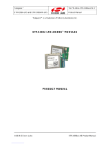
3 Package Contents
The package contains the following items,
Figure 1: Package contents
a. ZigBee Communications Gateway
b. Micro USB power cable
c. Mounting screws
(a)
(b)
(c)

ZigBee Communications Gateway
©2016 Silicon Labs -6- ZigBee Communications Gateway
4 Specifications
Model Number
GW357
RF Interface
ZigBee Pro
RF Output Power
+8dBm
Antenna
Half-wave Dipole Antenna 2dBi Gain or Integrated Antenna
Clock Battery
1x 3V 220mAh Sony CR2032 Battery
Power Source
5Volts @ 500mA via USB Micro Connector
Charging source should be current limited
Ethernet
RJ45 10/100Mbps
Power Over Ethernet
(optional)
802.3af Compliant Class 1 Device
Operating Temperature
-20 to 70C
Humidity
95% TH Non-condensing
IP Rating
IP20 (subject to testing)
Net Weight
110g
RS485/RS232
Baud rate: 2400, 4800, 9600, 19200, 38400, 57600, 115200
Parity: none, odd, even
Stop bits: 1 or 2
RS485 120Ω termination resistor built in
4.1 Order Codes
4.2 Examples
GW357-11-P-W-1-8 Gateway with 2xETRX357 module, Power-over-Ethernet, WiFi,
RS232/RS485 and an 8MB SD Memory Card
GW357-1 Basic Gateway with 1xETRX357 module
GW357-30-0-0-1 Gateway with 1xETRX357-LRS and RS232/RS485
GW
Gateway
GW357
Core Silabs IC
GW357-X
1st module
1 = ETRX357
2 = ETRX357HR
3 = ETRX357-LRS
4 = ETRX357-HR-LRS
GW357-0X
2nd module
GW357-00-X
Power of Ethernet (P)
GW357-00-0-X
WiFi or GSM (W or G)
GW357-00-0-0-X
RS232/RS485 (1=yes 0=No)
GW357-00-0-0-0-X
SD Memory Card size i.e. 4, 8 etc.

ZigBee Communications Gateway
©2016 Silicon Labs -7- ZigBee Communications Gateway
Layout
Figure 2: Gateway front view
Figure 3: Gateway without RS232/RS485 back view
Ethernet connector RJ45
Micro USB power socket
Button-2 (B2)
2
nd
ETRX3 Status LED
Interface Activity LED
Gateway Activity LED
Link Status LED
1st ETRX3 Status LED

ZigBee Communications Gateway
©2016 Silicon Labs -8- ZigBee Communications Gateway
Figure 4: Gateway with RS232/RS485 back view
1
1
Compatible connectors for RS232/RS485 port
MULTICOMP - MC000099
MULTICOMP - MC000107
MULTICOMP - MC000115
RS485 D-
RS485 D+
RS232 RX
GND
RS232 TX
Ethernet connector RJ45
Micro USB power socket
Button-2 (B2)

ZigBee Communications Gateway
©2016 Silicon Labs -9- ZigBee Communications Gateway
Figure 5: Gateway bottom view
Figure 6: Top label
Mounting holes
Opening for
battery and SD
card holder
Button-1 (B1)
Button-3 (B3)
Anti-slip pads
Anti-slip pads
Power supply
ratings
Gateway MAC
address

ZigBee Communications Gateway
©2016 Silicon Labs -10- ZigBee Communications Gateway
Figure 7: Bottom label
4.3 Power
The Gateway can be powered ON by plugging in the micro USB cable in the socket provided as
shown in figure-3 with power source as specified in the Specifications. Selected models of gateway
incorporating Power over Ethernet (PoE) can be powered on using the PoE injector through RJ45
cable.
Manufacture date
Gateway serial number
Gateway model number

ZigBee Communications Gateway
©2016 Silicon Labs -11- ZigBee Communications Gateway
4.4 LED Indicators
Sequence
Number
Gateway State
1
st
ETRX3
Status
LED
Link
Status
LED
Gateway
Activity LED
Interface
Active
LED
2
nd
ETRX3
Status
LED
1
Power UP Sequence
ON
Red +
Green
Blinking
Amber for
5 sec
OFF
ON
All LEDs will turn ON and then following blink one after
the other twice except for the ETRX3 Status LEDs
which are controlled by ETRX3 ZigBee modules
2
Ethernet link inactive
-
Red
Blinking
Amber
-
-
3
Ethernet link active
-
Green
OFF
-
-
4
Any socket connected to
either ZigBee module
OR
Web Terminal connected
-
-
-
Green
-
5
Any communication with
ZigBee modules
OR
Any communications on
Ethernet lines
-
-
Blinking
Amber
-
-
Table 2: LED Sequence table
2
nd
ETRX3 Status LED
Interface Active LED
Gateway Activity LED
Link Status LED
1
st
ETRX3 Status LED

ZigBee Communications Gateway
©2016 Silicon Labs -12- ZigBee Communications Gateway
4.5 Buttons Actions
The Gateway has three hardware buttons as shown in the Layout which can perform multiple
functions as described in this section.
1. Button 1 (B1)
2. Button 2 (B2)
3. Button 3 (B3)
Restore factory defaults
Follow the following procedure with buttons in order to restore the factory default configuration
settings on the Gateway using B3 and B1.
1. Press and hold B3
2. Then with B3 pressed, press and hold B1 for approximately 3 seconds after which the
Gateway reboots and LED power up sequence is seen.
Gateway reboot
Press B3 and hold for 5 seconds to reboot the Gateway.
Gateway recovery mode
Perform following procedure to put the Gateway in recovery mode
2
.
1. Press and hold B3 until gateway reboots.
2. At power up hold B2 and wait for 3 seconds.
3. The Gateway will be in recovery mode now.
Issue ZigBee command
Button B2 is used to issue custom ZigBee command to the 1
st
ETRX3 ZigBee module which can be
configured in Button Command section of the Gateway Configurations as shown below.
So whenever the B2 is pressed the command (“AT+BCAST:00,hello” by default) is issued to the 1
st
ETRX3 ZigBee module.
2
Recovery mode not implemented in initial release but will be added in subsequent release soon.

ZigBee Communications Gateway
©2016 Silicon Labs -13- ZigBee Communications Gateway
5 Functionality
5.1 Start-up
Turn ON the ZigBee Communications Gateway by inserting the micro USB power cable into the
socket shown in figure 3. The LEDs on the front panel will light up as described in the LED’s
Sequence table. Once the Start-up LED sequence is complete the gateway will continuously look for
an Ethernet link which is indicated by LED sequence-3. Insert the Ethernet cable in the RJ45 socket
shown in figure 3. The gateway will try to obtain an IP address by using DCHP (by default DHCP is
enabled but the user can also set static IP address for the Gateway). Once an IP address is allocated
successfully the LED sequence-4 is displayed on the LED panel.
5.2 Gateway Discovery
Discovery on a windows-7 PC
Gateway implements UPnP discovery service so the user can directly go to “Network settings” and
look for devices under “Network Infrastructure” category. The Gateway will show up as ZigBee
Communications Gateway as shown below. Navigate to properties by right clicking on the device to
view the device properties. Browse to the IP address shown in the device properties or alternatively
double click on the device to navigate to the webpage hosted by Gateway.
Figure 8: Device Discovery

ZigBee Communications Gateway
©2016 Silicon Labs -14- ZigBee Communications Gateway
Discovery on other platforms:
On other platforms where UPnP services are not available, the device can be discovered using the
following python script which basically listens to the UDP broadcast on port 14099 by the gateway
once every minute.
Run the above script from command line and the output window would show the IP addresses of
the ZigBee Communications Gateways in the network as shown below
Figure 10: Discovery Output
import socket, traceback, commands
host = '' # Bind to all interfaces
port = 14099
#start a udp socket server to listen on port 14099
s = socket.socket(socket.AF_INET, socket.SOCK_DGRAM)
s.setsockopt(socket.SOL_SOCKET, socket.SO_REUSEADDR, 1)
s.setsockopt(socket.SOL_SOCKET, socket.SO_BROADCAST, 1)
s.bind((host, port))
print "Waiting for Telegesis Gateway:"
while 1:
try:
message, address = s.recvfrom(8192)
print "Telegesis Gateway Found on IP Address:
%r"%(address[0])
except (KeyboardInterrupt, SystemExit):
raise
Figure 6: Discovery Script Figure 9: Discovery Python Script

ZigBee Communications Gateway
©2016 Silicon Labs -15- ZigBee Communications Gateway
5.3 Gateway Webserver
ZigBee Communication Gateway hosts a http webserver to serve webpages which help the user to
configure the Gateway and communicate with the ZigBee device via a simple web interface.
Authentication
The http webserver is protected by basic authentication hence a valid username “admin” and
password “password” must be provided when prompted to access the webpages. The password
can be changed through the GW357 Configuration webpage as explained in the later section.
Figure 11: HTTP server authentication

ZigBee Communications Gateway
©2016 Silicon Labs -16- ZigBee Communications Gateway
Web Pages
Following web pages are served by the http web server on the ZigBee Communications Gateway
5.3.2.1 GW357 Configuration
The Gateway configuration page is the main page of the http webserver. This page provides access
to the configuration parameters of the Gateway.
Figure 12: Configurations Page

ZigBee Communications Gateway
©2016 Silicon Labs -17- ZigBee Communications Gateway
5.3.2.1.1 Gateway Configuration
a. Current Firmware Info
This field gives information about the current firmware running on the gateway.
b. Web Terminal
This option enables or disables the access to ZigBee module via the web terminal. The
Gateway provides an access to the ZigBee module via Web Terminal page which can be
used to issue commands to the ZigBee module and monitor the response of the module. The
Web Terminal only supports communication in ASCII.
Default value is enabled.
c. Dialout TCP Sockets
Enable
The Gateway can establish an outgoing TCP socket connections to a specified dialout
addresses and port numbers. This option can enable or disable the outgoing socket
connections for both the ZigBee modules.
Default value is disabled.
Out 1 Address
The address specified in this option is used by the gateway to establish the outgoing socket
connection for the 1
st
ETRX3 ZigBee module. The dialout address can either be an IP
address or a host name.
Out 1 port
This item specifies the port number for the dialout connection from 1
st
ETRX3 ZigBee module.
Out 2 Address
3
The address specified in this option is used by the gateway to establish the outgoing socket
connection from the 2
nd
ETRX3 ZigBee module. The dialout address can either be an IP
address or a host name.
3
This option only available in Gateway models with two ZigBee modules on-board. Please refer order codes

ZigBee Communications Gateway
©2016 Silicon Labs -18- ZigBee Communications Gateway
Out 2 port
3
This item specifies the port number for the dialout connection from 2
nd
ETRX3 ZigBee
module.
Secure Connection
This option enables the SSL on the outgoing socket connection
4
.
d. Dialin TCP Sockets
Module 1 Enable
The Gateway also allows an incoming TCP socket connection on a specified port which
enables access to the 1
st
ETRX3 ZigBee module.
Module 1 Port
The IP port number to access the 1
st
ETRX3 ZigBee module via incoming TCP socket.
Module 1 IP Range MIN
The lowest IP address that can make a dial in socket connection to module 1 on gateway.
Module 1 IP Range MAX
The highest IP address that can make a dial in socket connection to module 1 on gateway.
Module 2 Enable
5
The Gateway also allows an incoming TCP socket connection on a specified port which
enables access to the 2
nd
ETRX3 ZigBee module.
Module 2 Port
5
The IP port number to access the 2
nd
ETRX3 ZigBee module via incoming TCP socket.
Module 2 IP Range MIN
5
The lowest IP address that can make a dial in socket connection to module 2 on gateway.
Module 2 IP Range MAX
5
The highest IP address that can make a dial in socket connection to module 2 on gateway.
4
The SSL is not implemented in current release.
5
This option only available in Gateway models with two ZigBee modules on-board. Please refer order codes

ZigBee Communications Gateway
©2016 Silicon Labs -19- ZigBee Communications Gateway
e. RS232/RS485 Tunnelling
This is only available on GW357 gateway models which have the RS232\RS485 option (see
the order codes table.) A “Module 2” check box will also be present if your GW357 has a
second ETRX3 ZigBee module fitted.
This option creates a direct connection between the RS232 or RS485 port on the gateway
and the ETRX3 ZigBee module.
The GW357 doesn’t support addressing in multidrop networks. Any data received on the
RS485 port will be automatically forwarded to the ETRX3 ZigBee module.
f. RS232/RS485 Port Configuration
This option is only available on GW357 gateway models which have the RS232\RS485 option
(see the order codes table.)
Here the user can select the RS232 and RS485 port settings. Note: it is recommended
(although not a requirement) that the RS232/RS485 port on the gateway and the ETRX3
ZigBee module have the same baud rate. The gateway has a limited capacity to buffer
messages; ensuring the baud rates are the same removes the potential for a buffer overflow
in the RX or TX paths.
g. Discovery
This option is enables the Gateway to send discovery broadcasts by UDP on port 14099
once every minute. This option is enabled by default.
h. Button Command
This is a command string that will be sent to the 1
st
ETRX3 ZigBee module each time the
Button-2 (B2) is pressed.

ZigBee Communications Gateway
©2016 Silicon Labs -20- ZigBee Communications Gateway
i. Gateway Time
Time Server
The Gateway implements SNTP client which can update Gateway time from a valid time
server specified in time server field.
Current Time
The current time of the gateway is displayed in this field when the page is loaded or
is clicked.
After changing any settings on the webpage must be clicked in order to apply the
changes to Gateway configuration. Following message will be displayed to confirm the
change.
j. Disable Web Server
The HTTP webserver running on the gateway can be disabled using this option on the
configurations page.
Once it is disabled only following page will be accessible to user. This feature is added to
avoid any unauthorized or unintended changes in the gateway configuration. A CGI-script
can be run on the gateway to re-enable the webserver. The CGI script to re-enable the
webserver is “en-wp.cgi”
/