Page is loading ...

BOILER INSTALLATION, OPERATION
INSTRUCTIONS
HOT WATER SUPPLY
Please Read Instructions Carefully
Save for Future Reference
CENTRAL HEATING AND DOMESTIC
Riva
COMBI
WALL HUNG GAS BOILER FOR
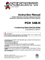
WARNING: If the information in this manual is not
followed exactly, a fire or explosion may result causing
property damage, personal injury or loss of life.
— Do not store or use gasoline or other flammable vapors and liquids
in the vicinity of this or any other appliance.
— WHAT TO DO IF YOU SMELL GAS
• Do not try to light any appliance.
• Do not touch any electric switch; do not use any phone in your
building.
• Immediately call your gas supplier from a neighbor’s phone.
Follow the gas supplier’s instructions.
• If you can not reach your gas supplier call the fire department.
— Installation and service must be performed by a qualified installer,
service agency or the gas supplier.
Manufactured by:
Biasi S.p.A.
V
erona, Ital
y
Distributed By:
Quincy Hydronic Technology, Inc.
3560 Lafayette Road
Portsmouth, NH 03801
Phone: 603-334-6400
Fax: 603-334-6401
RIVA COMBI MANUAL - REV B

RIVA COMBI MANUAL - REV B 2

Dear Customer:
Thank you for buying a Biasi Riva Combi Boiler System.
The Riva Combi is a high efficiency, non-condensing, wall mounted gas boiler which
provides central heat and domestic hot water.
We realize that it is not possible to answer all questions about the Riva Combi boiler
system in this manual. Reading this installation manual does not make the reader an
expert in all aspects of installation and operation, and does not replace the need for a
qualified, licensed heating contractor. We urge you to contact your installing contractor or
distributor if you are in question about any aspect of your boiler's performance. Our main
concern is that you are satisfied with your boiler and its performance. We require that your
contractor complete efficiency tests using instruments.
The external controls and accessories listed in this manual (excluding those supplied
inside the boiler) are intended to serve as guidelines rather than specific
recommendations. We realize that other makes and models of such devices are available
and can be used as successfully as those we specify. The installing contractor is the best
judge of a system's specific requirements, as well as the local availability of certain makes
and models of controls and accessories. The preceding does not apply, however, to the
equipment that comes with every boiler, such as the overheat control and pressure relief
valves. The installation of the specific devices supplied with every boiler is
absolutely necessary to the safe operation of the boiler and protection of the
heating system.
All BIASI wall hung boilers are built in accordance with the ASME boiler and pressure
vessel code, and bear the "H" stamp. The Entire range of applications for the Riva Combi
has been tested to standard CSA 4.9 and is CSA compliant.
This Riva Combi has a 2 year warranty, a copy of which is provided with the boiler. Please
be sure to return the warranty registration card as the warranty will be void without your
boiler's serial numbers (located on the ratings label affixed to the boiler), date of
installation and the name of your installer being on record in our files.
Thank you for purchasing our Riva Combi boiler. If you have questions or comments,
please don't hesitate to contact us immediately. Our goal is 100% customer satisfaction.
QHT inc.
RIVA COMBI MANUAL - REV B 3

Table of Contents
Section Title Section Number Page Number
Warnings - 6-7
Important Information - 8
General Information 1 9
Technical Information (M35.30CB) 2 9-10
Parts List 3 11
Internal Piping and Parts List 4 12
Electric Diagrams 5 13
Installation Location 6 14
Exhaust Pipe Location 7 15
Mounting Bracket 8 16
Venting 9 17-20
Restrictor Sizing 9.1 17
Fitting the Flue System 9.2 17
Choice of Flue 9.3 18-20
Pipe Connections 10 21
Gas Pipe Connections 11 22
Electrical Connections/Wiring 12 23-25
Power Connection 12.1 23
Connection to the Electricity Supply 12.2 23
Room Thermostat Connection 12.3 24
Relay Panel Connection 12.4 24
Zone Valve Microswitch Connection 12.5 25
Circulator Sizing 13 26
Circ. Cap. as a Function of Flow Rate 13.1 26
Expansion Vessels 13.2 26
Piping 14 27-29
Primary-Secondary Piping 14.1 27
Primary-Secondary with Zone Valves 14.2 28
RIVA COMBI MANUAL - REV B 4

Table of Contents
Section Title Section Number Page Number
Manifold Piping with Zone Valves or Circ. 14.3 29
Commissioning 15 30-35
Filling the D.h.w. System 15.1 30
Initial Filling of the System 15.2 30
Lightning the Boiler 15.3 31
Checking the Gas Pres. at the Burner 15.4 31
Adjustment of the Gas Pressure 15.5 32
Checking the Ignition Device 15.6 32
Checking the Burner Ignition 15.7 33
Adjustment of the Useful c.h. Output 15.8 33
Labels Placement 15.9 34
Checking the Flue System and Comb. 15.10 35
Instructing the User 15.11 35
Gas Conversion 16 36-37
Annual Maintenance 17 38-40
Warnings 17.1 38
Dismantelling the External Panels 17.2 38
Emptying the D.h.w. System 17.3 38
Emptying the C.h. System 17.4 38
Cleaning the Primary Heat Exch. 17.5 39
Checking the Pressuriz. in C.h. Vess. 17.6 39
Checking the Pressuriz. in D.h.w. Vess. 17.7 39
Checking the Magnesium Anode 17.8 39
Cleanig the Burner 17.9 39
Checking the Flue 17.10 39
Visual Inspection of Appliance 17.11 40
Gas Pressures and Soundness 17.12 40
RIVA COMBI MANUAL - REV B 5

Installer Notes 18 41
Boiler is certified as an indoor appliance. Do not install boiler outdoors or locate where
it will be exposed to freezing temperatures.
W
ARNING
WARNING: If the information in this manual is not followed
exactly, a fire or explosion may result causing property
damage, personal injury or loss of life.
— Do not store or use gasoline or other flammable vapors and liquids
in the vicinity of this or any other appliance.
— WHAT TO DO IF YOU SMELL GAS
• Do not try to light any appliance.
• Do not touch any electric switch; do not use any phone in your
building.
• Immediately call your gas supplier from a neighbor’s phone.
Follow the gas supplier’s instructions.
• If you can not reach your gas supplier call the fire department.
— Installation and service must be performed by a qualified installer,
service agency or the gas supplier.
Caution: Do not store or use flammable materials, chemicals or flammable
liquids, especially gasoline, in the vicinity of this heating appliance.
DANGER
RIVA COMBI MANUAL - REV B 6

• Stale or smelly air.
• The presence of soot or carbon in or
around the appliance.
• Very high unexplained humidity inside
the building.
WARNING
Any appliance that burns natural gas, propane gas, fuel oil, wood or coal is capable of
producing carbon monoxide (CO). Carbon Monoxide (CO) is a gas which is odorless,
colorless and tasteless but is very toxic. CO is lighter than air and thus may travel
throughout the building.
BRIEF EXPOSURE TO HIGH CONCENTRATIONS OF CO, OR
PROLONGED EXPOSURE TO LESSER AMOUNTS OF CO MAY
RESULT IN CARBON MONOXIDE POISONING. EXPOSURE CAN BE
FATAL AND EXPOSURE TO HIGH CONCENTRATIONS MAY RESULT
IN THE SUDDEN ONSET OF SYMPTOMS INCLUDING
UNCONSCIOUSNESS.
Symptoms of CO poisoning include the following:
dizziness vision problems shortness of breath
headache loss of muscle control unclear thinking
nausea weakness unconsciousness
The symptoms of CO poisoning are often confused with those of influenza, and the
highest incidence of poisoning occurs at the onset of cold weather or during flu season.
A victim may not experience any symptoms, only one symptom, or a few symptoms.
Suspect the presence of carbon monoxide if symptoms tend to disappear when
you leave your home.
The following signs may indicate the presence of carbon monoxide:
• Hot gasses from appliance, venting
system pipes or chimney, escaping into
the living space.
• Flames coming out around the appliance.
• Yellow colored flames in the appliance.
If any of the symptoms of CO occur or if any of the signs of carbon monoxide are
present, VACATE THE PREMISES IMMEDIATELY AND CONTACT A QUALIFIED
HEATING SERVICE COMPANY OR THE GAS COMPANY OR THE FIRE
DEPARTMENT.
ONLY QUALIFIED, LICENSED SERVICE CONTRACTORS SHOULD PERFORM
WORK ON YOUR BIASI RIVA COMBI BOILER.
RIVA COMBI MANUAL - REV B 7

IMPORTANT INFORMATION
Please read this page carefully.
• ALL BOILERS MUST BE INSTALLED IN ACCORDANCE WITH NATIONAL,
STATE AND LOCAL PLUMBING, HEATING AND ELECTRICAL CODES AND
ORDINANCES, AS WELL AS THE REGULATIONS OF THE SERVING
ELECTRICAL, WATER AND GAS UTILITIES.
• All systems should be designed by competent contractors, and only persons
knowledgeable in the layout and installation of heating systems should
attempt the installation of any boiler. It is the responsibility of the installing
contractor to see that all controls are correctly installed and operating
properly when the installation is completed.
• This boiler is intended for use, only with propane or natural gas. All
flammable liquids (especially gasoline), chemicals, rags, paper, wood
scraps, debris, etc., should be kept away from the boiler at all times. Keep
the boiler area clean and free of all fire hazards.
• Please read the literature and warranties supplied by the manufacturers of
the various accessory equipment. This equipment is warranted by the
respective manufacturers, not by Quincy Hydronic Technologies, Inc. Each
piece of equipment must be installed and used according to the
recommendations of the manufacturer.
Codes and Regulations:
Installation of the boiler and related equipment must conform to national, state and
local regulating agencies and codes applicable to the installation of the equipment.
In the absence of local requirements, the following codes apply:
A. ANSI/NFPA - #70 National Electric Code
B. ANSI/NFPA - #211 Chimneys and Vents
C. ANSI/NFPA - #Z223.1 National Fuel Gas Code
C. ANSI/NFPA - Domestic Gas Conversion Burner
D. CAN/CGA - B149 Installation Codes
E. ANSI/ASME - CSD-1
The above codes are available from:
National Fire Protection Association (NFPA)
Battery March Park
Quincy, Massachusetts, 02269
http://www.nfpa.org
CSA International
8501 E. Pleasant Valley Road
Cleveland, OH 44134-5575
http://www.csa-international.org
RIVA COMBI MANUAL - REV B 8

The Riva Combi is a high efficiency, non-condensing, wall mounted gas boiler which
provides central heat and domestic hot water. The boiler features a gas valve which
modulates the energy input from 44,000 BTU/h to 108,000 BTU/h. The boiler is shipped
fully assembled with the components listed on page 11. All units are pressure and
combustion tested at the factory prior to shipping.
Key Features:
• Wall mountable - saving valuable floor
space.
• Boiler operation recognition system -
should the boiler not be used for
longer than 24 hours, it then performs
a controlled system test to ensuring
the motorized components within the
boiler do not become inoperable due
to lack of use.
• Several flue options available
• Electronic spark ignition
• Safety flow switch - positioned on the
main circuit, which monitors the flow
and protects the main heat exchanger
from thermal shock should there be a
lack of water in the system.
• Gas valve modulation - the gas input
modulates based off central heating
and domestic hot water temperature
to within ± 2 ºF
• Frost protection - contains an integral
frost protection system to prevent frost
damage which can occur in areas
susceptible to very cold weather
conditions.
• Diagnostic information system
equipped with three LED diagnostic
lights for quick error assessment.
RIVA COMBI MANUAL - REV B 9
GENERAL
Height in
35.4
Width in
23.6
Depth in
18.1
Weight lb
172
DOMESTIC HOT WATER
Maximum temperature °F 140
Minimum temperature °F 100
Maximum pressure psi 116
Useful tank capacity gal 13.2
D.h.w circuit flow rate
ΔT = 30 °K gpm 3.99
Continous d.h.w production
ΔT = 25 °K gpm 4.54
Continous d.h.w. production
ΔT = 40 °K gpm 2.85
Preparation time min 7’57”
CENTRAL HEATING
Maximum working temp. °F 185
Temp. Regulation range* °F 100-176
Maximum pressure psi 30.0
Minimum pressure psi 4.35
Max head loss (at 4.4 GPM) ft 10
*At the minimum useful output
2. Technical Information (M35.30CB)
1. General Information

ENERGY CAPACITY
Nominal heat input
(0/2000ft) MBH 122.8
Nominal heat input
(2000/4500ft) MBH 116.7
Minimum heat input MBH 49.5
Maximum useful output
(0/2000ft) MBH 100.7
Maximum useful output
(2000/4500ft) MBH 95.9
Minimum useful output MBH 37.0
GAS SUPPLY PRESSURE
Gas Normal Min Max
Natural inwc 7.0 3.5 10.5
Propane inwc 11.0 8.0 12.0
GAS PRESSURE AT BURNER
Gas Min Max Ignition
Natural inwc 0.8 5.3 2.4
Propane inwc 1.4 9.0 5.2
FLUE DESIGN
Minimum Venturi pressure inwc 0.66
Flue pipe diameter
Coaxial in
2.25/4
3.25/5
Twin split pipes in 3.25/3.25
Nominal heat flow rate
(0/2000ft) MBH 122.8
Nominal heat flow rate
(2000/4500ft) MBH 116.7
Min Exhaust temperature °F 255
Max Exhaust temperature °F 302
INJECTORS No. Size
Natural 14 130
Propane 14 89
GAS FLOW RATE
Gas Min Max
Natural ft³/h 48.7 121.1
Propane lb/h 2.23 5.55
ELECTRICAL
Voltage V 120
Frequency Hz 60
Current A < 1.6
Power consumption W 176
FLUE GAS FIGURES
Gas Min Max
CO2 2.2% 6.9%
O2 17.0% 8.6%
CLEARANCE TO
COMBUSTIBLES
Front in 18
Back in 0
Top in 8
Sides in 2
Bottom in 8
Flue pipe enclosed in 2
Flue pipe free air in 0
2.Technical Information Cont.
RIVA COMBI MANUAL - REV B 10

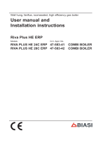
3. Parts List
Primary Components:
1
2
4
5
3
6
9
7
10
11
8
12
14
20
18
13
19
21
15
22
16
24
17
26
35
25
1 Pump
2 Pump vent plug
3 Automatic air purger valve
4 Modulation gas valve
5 Three-way diverter valve
6 D.h.w. expansion vessel
7 Flame-detecting electrode
8 Ignition electrodes
9 Burner
10 Combustion chamber
11 Primary heat exchanger
12 Fan
13 Air pressure switch
14 Air switch pres. Test points
15 Main circuit air breathe valve
16 D.h.w. storage tank
17 Safety thermostat
18 Modulation operator
19 Gas valve outlet pres. Test point
20 Gas valve inlet pres. Test point
21 Central heating expansion vessel
22 Central heating temp. Probe NTC
23 D.h.w. storage tank NTC
24 Central heating pressure relief valve
25 D.h.w. circuit pressure relief valve
26 Primary circuit flow switch
27 Main circuit drain cock
28 By-pass valve
29 Venturi device
30 Storage tank drain cock
31 Magnesium anode
32 Storage tank coil
33 Flue outlet pipe
34 Air Intake Pipe
35 Control panel
36 Safety thermostat probe
37 Pressure reducing automatic fill valve
38 Backflow preventer
39 Gas supply line cock
40 D.h.w. inlet cock
RIVA COMBI MANUAL - REV B 11

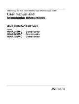
4. Internal Piping & Parts List
29
13
34
33
26
11
8
19
1
24
4
20
3
5
16
28
21
12
7
22
23
18
36
9
27
31
32
6
30
15
25
37
38
39
40
Note:
• Pressure Relief Valves (#24, #25) should be piped to a drain or to the floor as
close as possible to a drain.
• This diagram is a graphical representation only and is not drawn to scale. Do
not use for piping purposes.
RIVA COMBI MANUAL - REV B 12

ye bk wh gy bu rd
bk gy
gy
gy
M
~
M
~
tt
probe NTC
D.h.w. Temperature
Probe NTC C.h. temperature
COM
NO
M
~
COM
NO
NC
123 bk
bubn
rd
rd
gnyegywh
bu
rd
bk
bu
wh
gybugnye
bk bk
rd bk wh gygnye bu
bk
bk
bubu
bu
bu
rdbk
gygy
bubn
bn
bu
L N
rd bu bn gnye gnye
gnye bubn
burd
gnye
rd
wh
bk
Flow Switch
Primary Circuit
diverter valve
Three way Pump
Valve
Gas
External Controls
Terminal
Block
Electric Supply
Terminal
Block
Fan Safety
Thermostat
Air Pressure
Switch
Ignition
Electrodes
Flame Detection
Electrode
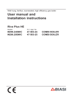
bn - brown
bu - blue
bk - black
wh - white
rd - red
gy - grey
ye - yellow
vt - violet
og - orange
gnye - green/yellow
1
3
2
wh
gy
rd
rd
bk
bu
bn
gy
ye wh bu rd
1
bk
rd
*
* ---> directly connected to the electronic ignition board
5. Electric Diagrams
Caution: Label all wires prior to disconnection when
servicing controls. Wiring errors can cause
improper and dangerous operation.
Verify proper operation after servicing
RIVA COMBI MANUAL - REV B 13

5.1 Sequence of Operation
RIVA COMBI MANUAL - REV B 14

6. Installation Location
The installation location chosen must:
• Comply with all clearances listed below.
• Provide suitable location for the exhaust and intake venting.
• Not be installed in an unheated space.
• Comply with all local codes and standards.
Note: Dimensions shown are minimums. Greater clearances will simplify
installation and service.
18.0 in
8.0 in
3
2.0 in
23.8 in
10.0 in
2.0 in
5.
3.0 in SE T
A
LL
A
TIT INS ONCLO NAMINIMUM PE
R
MA NT
RA NCECLEA
5 in
18.0
SE T
A
LL
A
TICLO T INS ON
EA RA NSER
V
ICECL CE
FRONT
V
IEW SIDE
V
IEW CLOSET
INSTALLATION
Figure 6.1
WARNING: Do not install the boiler on carpeting
If the boiler is to be installed in an enclosed room with no fresh air intake, the room must
have proper vent louvers installed. There should be two louvers, place each within 12” of
the ceiling and floor respectively. Each vent will have a free area of 54 square inches.
Outside
Air Opening
Air Opening
Each opening free area =
1 sq. inch per 2,000 BTU/h
0 to 12"
0 to 12"
Note: For boilers in an enclosed
space it is recommended to install
a CO detector in the boiler room.
Figure 6.2
When choosing an installation location insure the exhaust and intake pipes comply with
NFPA 54. The drawing on the next page illustrates the restrictions on exhaust locations.
RIVA COMBI MANUAL - REV B 15

7. Exhaust Pipe Location
CAUTION
EXTERNAL VENT SURFACES ARE HOT.
NOTE: USE ONLY LISTED COMPONENTS SUPPLIED WITH THE BOILER.
SURFACE DISCOLORATION OF THE BUILDING MAY OCCUR DUE TO
IMPROPER INSTALLATION. QHT WILL NOT ACCEPT RESPONSIBILITY O
R
LIABILITY FOR SUCH DISCOLORATION.
IT IS RESPONSABILITY OF THE HOMEOWNER TO KEEP THE VENT
TERMINAL CLEAR OF SNOW AND ICE
The Exhaust Hood must be installed on the leeward side of house and conform to
the following guidelines:
1. The Vent hood shall not be less than 3 feet above any forced air inlet to the house.
2. The Vent hood shall not be less than 1 foot below, 1 foot horizontally, or 1 foot above
any door, window or gravity inlet into any building.
3. The Vent hood shall not be less than 2 feet from an adjacent building.
4. The Vent hood shall be not less than 7 feet above grade when located adjacent to
public walkway.
5. The Vent hood shall be located so that flue gasses are not directed to jeopardize
people, overheat combustible structures, materials or enter buildings.
6. Minimum of 6 feet horizontal clearance from electric meters, gas meters, regulators
and relief equipment.
7. All joints in system are to be sealed to prevent leakage of products of
combustion in the building.
8. Avoid installing exhaust hood on the North, West, or the side of the house receiving
the prevailing winds.
9. The vent should not be situated so that the flue gases are directed towards brickwork,
siding, or other construction, in such a manner that may cause damage from heat or
RIVA COMBI MANUAL - REV B 16

condensate from the flue gases
8. Mounting Bracket
After a suitable installation location is chosen, verify that the mounting wall is
properly braced and strong enough to support the 300 pound weight of the unit
when filled with water.
NOTE: The boiler shall be installed such that the gas ignition system components
are protected from water and liquids in general (dripping,spraying, rain, etc)
during the appliance operation and service.
Use the paper template provided with the boiler to determine the location of the mounting
bracket. Securely mount the bracket to the wall using appropriate hardware for the
particular wall construction.
Mounting Steps:
1. Tape the paper template to the wall in the chosen location. Be sure to level the
template.
2. Pre-drill two holes in the center of the “oval” slots on the mounting bracket, sized
for the hardware being used.
3. Mount the bracket to the wall. Be sure to level the bracket by adjusting the screw
in the vertical slot.
4. Pre-drill the remaining hole in the mounting bracket and secure the final screw.
5. Mark and drill the exhaust/intake pipe holes through the house. If you are using a
coaxial pipe system, drill the hole marked A (ø 4”) in the drawing below and on the
paper template. If you are using a separate pipe system drill holes marked B and
C (ø 3.25”) shown below as well as on the paper template.
6. Remove paper template and hang boiler on bracket.
RIVA COMBI MANUAL - REV B 17

5.3
3.3
3.0
3.7
Figure 8.1
The Riva is a mechanical draft, side wall vented boiler. There are two side wall flue
options available – separate and coaxial. The coaxial option has one configuration shown
on the next page. The separate option has two possible configurations shown on the
following pages. There is also a vertical roof venting option. Regardless of what vent kit
is installed, they should all conform to the Provisions for combustion and ventilation air in
accordance with section 5.3, Air for Combustion and Ventilation, of the National Fuel Gas
Code, ANSI Z223.1, or Sections 7.2, 7.3 or 7.4 of CAN/CGA B149, Installation Codes, or
applicable provisions of the local building codes.
If the Biasi Riva replaces a boiler that was attached to a common vent system, the
common venting system is likely to be too large for proper venting of the appliances
remaining connected to it. To ensure the remaining appliances will function properly, the
test procedure below should be followed:
At the time of removal of an existing boiler, the following steps shall be followed with
each appliance remaining connected to the common venting system placed in
operation, while the other appliances remaining connected to the common venting
system are not in operation.
A. Seal any unused openings in the common venting system.
B. Visually inspect the venting system for proper size and horizontal pitch and
determine there is no blockage or restriction, leakage, corrosion and other
deficiencies which could cause an unsafe condition.
C. insofar as is practical, close all building doors and windows and all doors between
the space in which the appliances remaining connected to the common venting
23.6
3.0 15.7
1.4 0.6
2.0 3.3 2.8 7.6 2.6
2.3
35.4
1.4
1.5
1.5
B
Gas
pe
pe
rn
A
C
C.h. Supply
D.h.w. outlet pi
D.h.w. inlet pi
Supporto di
fissaggo
caldaia
7.5
11.2 C
A e B
18.1
D.h.w.
PRV
C.h.
PRV
C.h. retu
9. Venting
RIVA COMBI MANUAL - REV B 18

system are located and other spaces of the building. Turn on clothes dryers and
any appliance not connected to the common venting system. Turn on any exhaust
fans, such as range hoods and bathroom exhausts, so they will operate at
maximum speed. Do not operate a summer exhaust fan. Close fireplace dampers.
D. Place in operation the appliance being inspected. Follow the lighting instructions.
Adjust thermostat so appliance will operate continuously.
E. Test for spillage at the draft hood relief opening after 5 minutes of main burner
operation. Use the flame of a match or candle, or smoke from a cigarette, cigar or
pipe.
F. After it has been determined that each appliance remaining connected to the
common venting system properly vents when tested as outlined above, return
doors, windows, exhaust fans, fireplace dampers and any other gas-burning
appliance to their previous condition of use.” (g) Any improper operation of the
common venting system should be corrected so the installation conforms with the
National Fuel Gas Code, ANSI Z223.1 and/or CAN/CGA B149, Installation Codes.
When resizing any portion of the common venting system, the common venting
system should be resized to approach the minimum size as determined using the
appropriate tables in Part 11 of the National Fuel Gas Code, ANSI Z223.1 and/or
CAN/CGA B149, Installation Codes.
9. Venting Cont.
The Riva is a mechanical draft, side wall vented boiler. There are two flue options
available - separate and coaxial. The coaxial option has one configuration shown on the
next page. The separate option has two possible configurations shown on the following
pages.
9.1 Restrictor Sizing:
Each exhaust option is shipped standard with 3 feet of exhaust pipe, 3 feet of intake air
pipe. There is also a restrictor kit in which there are some restrictors that must be placed
in exhaust breech of fan on the top of the boiler (Fig. 9.1) according to the flue
configuration used.
If additional flue piping is need for a particular application, it can be ordered separately in
3 feet increments. Depending on the final flue pipe length, an alternative restrictor may be
required. Refer to the tables 9.1 for proper restrictor ring sizing
RIVA COMBI MANUAL - REV B 19

Figura 9.1
Coaxial 2.5/4.0 Restrictor Size
From 1.65 to 3.30 (ft) 41
From 3.30 to 8.86 (ft) 44
Separate 3.25/3.25 Restrictor Size
For 1.65 (in) and 1.65 (out) 38
From 3.30 to 39.40 (in+out) 41
Table 9.1
9.2 Fitting the flue system:
In general, it has to be taken in consideration that the orizontal sections of the flue
pipe must have an horizontal sloping not less than 1.5 degree (0.3 in per ft) towards
the boiler.
8. Venting Cont.
In the standard horizontal flue kit the flue pipe is angled within the air duct therefore the air
duct must be horizontally installed.
If one or more exstensions have to be used they must be adequately supported so that
there is no sag in the flue pipe and a minimum fall of 1.5 degree (0.3 in per ft) over the
whole lenght towards the boiler is ensured.
9. Venting Cont.
9.3 Choice of flue:
The following flue kits are available for connecting to the boiler:
A Standard coaxial horizontal flue kit (Exhaust & intake outside)
RIVA COMBI MANUAL - REV B 13
/