Page is loading ...

Wall hung, fanflue, roomsealed, high efficiency gas boiler
Service manual
Riva Plus HE
Models G.C. Appl. No.
M296.24SM/C 47-583-24 COMBI BOILER
M296.28SM/C 47-583-25 COMBI BOILER
Leave this manual adjacent to the gas meter
Warning:
Service / repairs must be carried out, only by a qualified Gas Safety
Registered Engineer, who will be responsible for the current Regulations for
gas appliances.
Note:
After servicing, complete the relevant Service Interval Record section of the
Benchmark Checklist of the user and installation manual.


- 3 -
TABLE OF CONTENTS
1 OVERALL INFORMATION .................... 4
1.1 Overall View ................................4
1.2 Hydraulic diagram ............................4
2 GENERAL ACCESS AND EMPTYING HYDRAULIC
CIRCUITS ................................. 5
2.1 Nomenclature ...............................5
2.2 Body panels ................................5
2.3 Control panel................................5
2.4 Access to the sealed chamber ..................6
2.5 Emptying the primary circuit ....................6
2.6 Emptying the d.h.w. circuit .....................6
3 DIAGRAMS................................ 7
3.1 Wiring diagram ..............................7
3.2 Functionalowdiagrams ......................8
3.3 Circuit voltages ..............................9
4 FAULT FINDING ........................... 10
5 PRIMARY HEAT EXCHANGER . . . . . . . . . . . . . . . 12
5.1 Function ..................................12
5.2 Removal ..................................12
5.3 Cleaning ..................................12
6 CONDENSING HEAT EXCHANGER . . . . . . . . . . . 13
6.1 Function ..................................13
6.2 Removal ..................................13
6.3 Cleaning ..................................14
7 D.H.W. HEAT EXCHANGER.................. 15
7.1 Function ..................................15
7.2 Removal ..................................15
8 PUMP ................................... 16
8.1 Function ..................................16
8.2 Checks ...................................16
8.3 Removal pump .............................16
8.4 Removal electrical capacitor ...................17
9 THREE WAY DIVERTER VALVE .............. 18
9.1 Function ..................................18
9.2 Checks ...................................18
9.3 Removal of the electric actuator ................18
9.4 Removal of the tree way diverter valve ...........19
9.5 Removal of the diverter group..................19
10 ELECTRONIC CONTROL/IGNITION P.C.B. ..... 20
10.1 Function ..................................20
10.2 Selection and adjustment devices...............20
10.3 Checking the temperature.....................21
10.4 Operation lights .............................22
10.5 Setting the boiler control function modes .........22
10.6 Useful output setting .........................22
10.7 Reignition frequency setting ...................23
10.8 Ignition gas pressure adjustment ...............24
10.9 Settingthed.h.w.owmeteroperationmode ......24
10.10 Checks ...................................25
10.11 Removal of the electronic control p.c.b ...........25
10.12 Thermal control in the mode ................27
10.13 Thermal control in the mode ................27
10.14 Ignition and control sequence ..................28
11 MODULATING GAS VALVE .................. 29
11.1 Function ..................................29
11.2 Nomenclature of the parts.....................29
11.3 Adjustment ................................29
11.4 Checks ...................................30
11.5 Removal of the on-off operators coils ............30
11.6 Removal of the gas valve .....................30
12 PRIMARY CIRCUIT PRESSURE SWITCH ...... 31
12.1 Function ..................................31
12.2 Checks ...................................31
12.3 Removal ..................................31
13 EXPANSION VESSEL AND TEMPERATURE-PRES-
SURE GAUGE ............................ 32
13.1 Function ..................................32
13.2 Checks ...................................32
13.3 Removal of the expansion vessel ...............32
13.4 Removal of the temperature-pressure gauge ......32
14 D.H.W. FLOWMETER, FILTER AND FLOW LIMITER
33
14.1 Function ..................................33
14.2 Description and location of parts - (Figure 14.2) ....33
14.3 Removal of the sensor .......................33
14.4 Checks ...................................33
14.5 Removaloftheowswitchgroupandd.h.w.circuit
lter ......................................33
14.6 Flow limiter ................................34
15 TEMPERATURE PROBE . . . . . . . . . . . . . . . . . . . . 35
15.1 Function ..................................35
15.2 Checks ...................................35
15.3 Removal of the c.h. temperature probe...........35
15.4 Removal of the d.h.w. temperature probe .........35
16 BY-PASS VALVE .......................... 37
16.1 Function ..................................37
16.2 Removal ..................................37
17 FAN AND AIR PRESSURE SENSOR........... 38
17.1 Function ..................................38
17.2 Checks ...................................38
17.3 Removal of the Fan..........................39
17.4 Removal of the Air pressure sensor .............39
18 IGNITION AND DETECTION ELECTRODES .... 40
18.1 Function ..................................40
18.2 Checks ...................................40
18.3 Removal ..................................40
19 SAFETY THERMOSTAT..................... 41
19.1 Function ..................................41
19.2 Checks ...................................41
19.3 Removal ..................................41
20 FLUE TEMPERATURE PROBE NTC........... 42
20.1 Function ..................................42
20.2 Checks ...................................42
20.3 Removal ..................................42
21 CONDENSATE TRAP....................... 43
21.1 Function ..................................43
21.2 Removal ..................................43
22 SHORT SPARE PARTS LIST................. 44

- 4 -
OVERALL INFORMATION
1 OVERALL INFORMATION
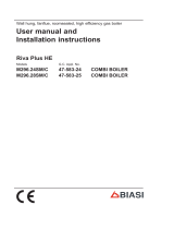
1.1 Overall View
Fan
Safety
thermostat
Mainheat
exchanger
Burner
Ignition
electrodes
Gasvalve Control
panel
Combustion
chamber
Automatic
air release
Pump
D.h.w.temp.
probe
Expansion
vessel
Detection
electrode
valve
Condensing
Divertervalve
Flue temperature
probe NTC
Primarycircuit
Combustion
chamber over heat
heat exchanger
Condensate
trap
pressureswitch
Airpressur sensor
C.h.temp.
probe
D.h.w. heat
exchanger
Figure 1.1
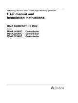
1.2 Hydraulic diagram
Figure 1.2
Centralheating (c.h.) operationDomestichot water(d.h.w.) operation
C.h.
waterflow
C.h.
waterreturn
D.h.w.
inlet
D.h.w.
outlet

- 5 -
GENERAL ACCESS AND EMPTYING HYDRAULIC CIRCUITS
2 GENERAL ACCESS AND EMPTYING
HYDRAULIC CIRCUITS
2.1 Nomenclature
Figure 2.1
6
1
2
3
4
5
1 Right side panel
2 Front panel
3 Control panel lid
4 Control panel cover
5 Service panel
6 Left side panel
2.2 Body panels
Warning: isolate the boiler from the mains electrici-
ty supply before removing any covering or compo-
nent.
For the most part of the check and maintenance operations it is
necessary to remove one or more panels of the case.
The side panels can be removed only after the removal of the
front panel.
To remove the front panel remove screws A (Figure 2.2), lift the
panel and remove it.
Figure 2.2
A
To remove the side panels loosen the screws B and C (Figure
2.3), bring the base of the panels away from the boiler and lift
them, freeing them from the top hooks.
Figure 2.3
D
B
C
- bottom view of the boiler
2.3 Control panel
Warning: isolate the boiler from the mains electrici-
ty supply before removing any covering or compo-
nent.
To gain access to the parts located inside the control panel pro-
ceed as follows:
1 Remove the front panel of the case
2 Loosen the screws B and C (Figure 2.3).
3 Remove the screws D
4 Move the lower part of the side panels as indicated in Figure
2.4 and pull the control panel.
When completely pulled out, the panel can rotate 45° down-
wards to facilitate the service operations on the internal parts.

- 6 -
GENERAL ACCESS AND EMPTYING HYDRAULIC CIRCUITS
Figure 2.4
5 Remove the screws E and remove the service panel (Figure
2.5);
6 To gain access to the electronic regulation PCB remove the
screws F and remove the control panel lid (Figure 2.5);
Figure 2.5
E
F
F
2.4 Access to the sealed chamber
Figure 2.6
G
G
To gain access to the parts contained in the sealed chamber it is
necessary to remove the lid of the sealed chamber. For this pur-
pose, remove the front and side panels of the case, remove the
screws G as indicated in Figure 2.6 and remove the lid.
2.5 Emptying the primary circuit
1 Closethec.h.circuitowandreturncocks.
2 Remove the front and right panels of the boiler.
3 Open the drain tap I (Figure 2.7) until the boiler is completely
emptied.
4 Close drain tap again once the emptying has been complet-
ed.
Figure 2.7
I
2.6 Emptying the d.h.w. circuit
5 Close the d.c.w. inlet cock;
6 Open one or more hot water taps until the boiler has been
completely emptied.

- 7 -
DIAGRAMS
3 DIAGRAMS
3.1 Wiring diagram
Figure 3.1
5V
OUT
GND
123
L N
gnye bubn
bn
bkbu
bn bubn bk bu
gnye
M
~
bn bu
bn
bu
M
~
bu bn gnye
bkbk
t
wh
wh
tbu
bu
rd
wh
bu
trd
rd
bk
bk
Time switch
rd
bk
gn
Ignition
electrodes Flamedetection
electrode
Externalcontrols
terminal block
Electric supply
terminal block
Threeway
diverter valve
Pump
M
~
Primarycircuit
pressure switch
Airpressure
sensor
D.h.w.
flowmeter
C.h. temperature
probeNTC
Modulating
gasvalve
Safety
thermostat
Flue
probeNTC
D.h.w. temperature
probeNTC
ye
gy
bn =brown
bu =blue
bk =black
wh =white
rd =red
gy =grey
gn =green
ye =yellow
vt =violet
og =orange
gnye =green/yellow
bubn gnye
bu
bu
bk
bu bu
bn
bu
bk wh
wh
rd
rd
gn
wh
bk
rd
P
rd
ye
gy
rd
gy
ye
gy
gy
bk
bk
ye
gy
rd
rd
wh
rd
1
2
3
1
3
4
bu
bu
bk bn bu
bk bu bn
gnye
wh
bk
Combustion
chamber
over heat
bk
bk bk
bk
Fan
bu

- 8 -
DIAGRAMS
3.2 Functional ow diagrams
Figure 3.2
PTCJ1---1
L
General layout
Transformer
N
Electronic
controlp.c.b.
(low voltagesection)
J1---2
J3---3
J3---5
J3---4
J3---2J3---1
J2---4J2---5
Threeway
diverter valve
Pump
Full sequence
ignition device
Fuse 3,15 A
PTCJ1---1
L
Transformer
ACTIVE CIRCUIT
INACTIVE CIRCUIT
L--- LINE N--- NEUTRAL
N
Electronic
controlp.c.b.
(low voltagesection)
J1---2
J3---3
J3---5
J3---4
J3---2J3---1
J2---4J2---5
Threeway
diverter valve
Pump
Full sequence
ignition device
Fuse 3,15 A
Heat request on d.h.w.
PTCJ1---1
L
Transformer
N
Electronic
controlp.c.b.
(low voltagesection)
J1---2
J3---3
J3---5
J3---4
J3---2J3---1
J2---4J2---5
Threeway
diverter valve
Pump
Full sequence
ignition device
Fuse 3,15 A
Heat request on c.h.


- 10 -
FAULT FINDING
Components to check
Section of the manual !
(note ref. in brackets)
---
(1)
---
(2)
---
(3)
21.1 ---
(4)
78.2 9.2 10.10 11.4 12.2 14.5 15.2 16 17.2 18.2 19.2 20.1 ---
(7)
---
(8)
--- ---
L o c k --- o u t s i g n a l l a m p r e d
Defect
#
Power supply line
Gas supply line
Flue pipes
Condensate drain pipe and trap
C.h. circuit
D.h.w. circuit
D.h.w. heat exchanger
Pump
Diverter valve
D.h.w. flow switch
Fuses (Electronic p.c.b.)
Electronic p.c.b.
Boiler settings
Gas valve (on--- off operators)
Gas valve (modulating operator)
Main circuit pressure switch
D.h.w. filter
Main circuit temp. probe
D.h.w. temp. probe
By--- pass valve
Fan
Air pressure sensor
Ignition electrode
Detection electrode
Safety thermostat
Flue probe NTC
Injectors
Expansion vessel
Safety valve
Pressure gauge
By pressing the reset push --- button
the boiler turns on and operates cor-
rectly.
J J
(6)
J J J
By pressing the reset push --- button
the boiler starts the ignition cycle.
The burner doesn’t light on, the igni-
tion sparks continue and the boiler
locks again.
J J J J J
ON
By pressing the reset push --- button
the boiler starts the ignition cycle.
The burner lights on, the ignition
sparks continue and the boiler locks
again.
J J J J J J
The boiler does not start either in c/h
or d.h.w. mode.
All the operation lights OFF
Fan still.
J J J
The burner doesn’t light either in c.h.
or d.h.w. mode.
Fan turns.
J J J J J
The burner doesn’t light either in c.h.
or d.h.w. mode.
Fan doesn’t turn.
J J J J J J J J
The boiler doesn’t control the d.h.w.
temperature.
Turning the d.h.w. temp. adjustment
knob hasn’t effect on the modulation
of the flame.
The boiler operates correctly on c.h.
J J
OFF
The boiler lights for a short while on
c.h.
Normal operation on d.h.w. function.
J J
4 FAULT FINDING

- 11 -
FAULT FINDING
Section of the manual !
(note ref. in brackets)
---------
(8)
---
(7)
20.119.218.217.21615.214.512.211.410.109.28.27---
(4)
21.1---
(3)
---
(2)
---
(1)
L o c k --- o u t s i g n a l l a m p r e d
Pressure gauge
Safety valve
Expansion vessel
Injectors
Flue probe NTC
Safety thermostat
Detection electrode
Ignition electrode
Air pressure sensor
Fan
By--- pass valve
D.h.w. temp. probe
Main circuit temp. probe
D.h.w. filter
Main circuit pressure switch
Gas valve (modulating operator)
Gas valve (on--- off operators)
Boiler settings
Electronic p.c.b.
Fuses (Electronic p.c.b.)
D.h.w. flow switch
Diverter valve
Pump
D.h.w. heat exchanger
D.h.w. circuit
C.h. circuit
Condensate drain pipe and trap
Flue pipes
Gas supply line
Power supply line
Defect
#
The boiler does not supply d.h.w.
(cold water from the tap).
Regular operation in c/h mode even
during a drawing off d.h.w.
J J J
On c/h mode the temperature of the
main circuit reaches 75C and the c/h
system does not heat.
The boiler operates correctly on
d.h.w. mode.
J J
Incorrect modulation J J J
Noisy bolier J J
The boiler operates correctly but the
gas pressure to the burner remains
at minimum.
J J
F
Poor d.h.w. temperature J J J J J
(9)
OF
F
Low d.h.w. flow rate J J J
---
Water leaks from the safety valve dur-
ing operation on c/h
J J J J
---
Water leaks from the safety valve
when the boiler is off.
J J J
Note
Useful information can be obtained also from the
optical indication given by the appliance oper-
ation lights (see section 10.4).
1 Check for 230V~ between line (L) and neutral (N)
Verify the integrity of supply cable, plug and external fuses.
Check the polarity of line and neutral connection
2 Verify the tightness of the gas supply pipe, the position of stop
valves.
Check the gas pressure at the inlet test point of the gas valve
(see sect. 11.3) with the boiler at rest and during operation and
compare it with the values given on the installation booklet.
3 Check for soundness and absence of obstructions. Verify that
the flue terminal is correctly installed (see clearances) and en-
sure that exhaust gas is not sucked back by the boiler.
4 Check for soundness of the circuit and verify its correct filling
(see also installation manual).
5 A jammed by---pass could cause the over---heating of the main
circuit and the intervention of the safety thermostat.
6 Check the minimum gas pressure at the outlet test point of the
gas valve (see sect. 11.3) and compare it with the value given
on the installation booklet.
7 Verify the cleanness of injectors.
8 Check the pressurization of the expansion vessel. Refer to the
installation manual for proper values.
9 d.h.w. pressure too high or flow rate too high. If necessary in-
sert a flow rate limiter (14.6)

- 12 -
PRIMARY HEAT EXCHANGER
5 PRIMARY HEAT EXCHANGER
5.1 Function
The primary heat exchanger A in Figure 5.1 has the function of
transferring heat produced from combustion of the gas to the
water circulating in it.
Figure 5.1
A
The hydraulic circuit is composed of 8 elliptical pipes connected
in parallel (Figure 5.2).
Figure 5.2
5.2 Removal
Warning: isolate the boiler from the mains electrici-
ty supply before removing any covering or compo-
nent.
1 Remove the case panels and the sealed chamber lid (section
"Body panels" page 5).
2 Empty the primary circuit of the boiler.
3 Remove the combustion chamber lid B by unscrewing the
screws C (Figure 5.3).
4 Remove the screws D and the plate E.
5 Remove the clip F.
6 Loosen the connection G and slightly move the pipe H up-
wards.
7 Remove the clip I and the safety thermostat J and the c.h.
temperature probe K. It is not necessary to disconnect it from
the wiring.
Figure 5.3
F
H
N
P
J
I
K
M
E
O
G
C
B
C
D
L
8 Loosen the connection L and move the pipe M downwards
freeing it from the connection of the primary het exchanger.
9 Remove the clip N.
10 Loosen the connection O.
11 Free the pipe P from the connection of the condensing heat
exchanger; lift and rotate it towards right.
12 Remove the heat exchanger by sliding it forwards.
13 Reassemble the boiler carrying out the removal operations in
reverse order. Fit the clip I with the arrow pointing upwards as
illustrated in Figure 5.3.
IMPORTANT: do not force the connection G when
tighting it.
5.3 Cleaning
If there are deposits of soot or dirt between the blades of the heat
exchanger, clean with a brush or non-metallic bristle brush.
In any case, avoid any actions that can damage the protective
varnish with which the exchanger has been covered.
Warning: After cleaning or replacement as detailed
above, if it deemed necessary to undertake a com-
bustion analysis, refer to the appropriate chapter
Maintenance of the installation instructions manual.

- 13 -
CONDENSING HEAT EXCHANGER
6 CONDENSING HEAT EXCHANGER
6.1 Function
ThereturnwaterowsthroughthecondensingheatexchangerA
in Figure 6.1 and Figure 6.2.
By reducing the combustion products temperature, the latent
heat of the vapour is transferred to the water circuit, allowing an
extra gain of useful heat.
The condensed vapour is then drained through the condensate
trap B and the draining pipe C.
Figure 6.1
A
B
C
6.2 Removal
Warning: isolate the boiler from the mains electrici-
ty supply before removing any covering or compo-
nent.
1 Remove the case panels and the sealed chamber lid (section
"Body panels" page 5).
2 Empty the primary circuit of the boiler.
3 Remove the fan D in Figure 6.2 (see section "Removal of the
Fan" page 39).
4 Disconnect the connectors of the ue temperature probe
NTC E.
5 Remove the clip F.
6 Completely loosen the connection G and slightly move the
pipe H upwards.
7 Remove the clip I.
8 Loosen the connection J.
9 Free the pipe K from the connection of the condensing heat
exchanger; lift and rotate it towards right.
10 Using pliers, remove the spring L moving it to wards right and
disconnect the rubber pipe M.
11 Rotate the exchanger as indicated by the arrow and remove
it towards the front of the boiler.
Figure 6.2
A
E
F
H
I
D
L
M
G
K
J
12 Reassemble the exchanger carrying out the removal opera-
tions in reverse order.
Warning: to lubricate the O-ring gaskets exclusively
use a silicone base grease compatible to be in con-
tact with foods and approved by the local water Au-
thorities.
After reassembling ensure that the fan-exchanger and ex-
changer-elbow gaskets are correctly mounted and ensure a
good sealing.
Warning: After cleaning or replacement as detailed
above, if it deemed necessary to undertake a com-
bustion analysis, refer to the appropriate chapter
Maintenance of the installation instructions manual.

- 14 -
CONDENSING HEAT EXCHANGER
6.3 Cleaning
1 Using pliers, remove the spring L moving it to wards right and
disconnect the rubber pipe M (Figure 6.3).
2 Unscrewing the screws N (Figure 6.3).
3 Remove the condensing heat exchange lid O (Figure 6.3)
moving towards the front of the boiler.
If there are deposits of soot or dirt on the exchanger lid, clean
with a brush or non-metallic bristle brush.
Figure 6.3
N
O
L
M
4 Reassemble the exchanger carrying out the removal opera-
tions in reverse order.
Warning: to lubricate the O-ring gaskets exclusively
use a silicone base grease compatible to be in con-
tact with foods and approved by the local water Au-
thorities.
Warning: After cleaning or replacement as detailed
above, if it deemed necessary to undertake a com-
bustion analysis, refer to the appropriate chapter
Maintenance of the installation instructions manual.

- 15 -
D.H.W. HEAT EXCHANGER
7 D.H.W. HEAT EXCHANGER
7.1 Function
The d.h.w heat exchanger A in Figure 7.1 and Fig. 4 allows the
instantaneous transfer of heat from the primary hydraulic circuit
to the water destined for d.h.w use.
Figure 7.1
A
The schematic structure is shown in Figure 7.2.
Figure 7.2
Primaryhydraulic circuit
Domestic hotwater circuit
7.2 Removal
Warning: isolate the boiler from the mains electrici-
ty supply before removing any covering or compo-
nent.
1 Remove the front and right hand side panels of the case.
2 Empty the primary circuit and the d.h.w circuit of the boiler.
3 Remove the pump B in Figure 7.3 (see section "Removal
pump" page 16).
4 Remove the clip C and remove the primary circuit pressure
switch D by lifting it upwards. It is not necessary to disconnect
it from the wiring.
5 Remove the clip E and remove the electric actuator F by pull-
ing it. It is not necessary to disconnect it from the wiring.
Figure 7.3
B
E
F
D
C
6 Completely unscrew the two Allen key screws G (Figure 7.4)
which hold the exchanger to the plastic groups.
Figure 7.4
A
G
7 Move the exchanger towards the rear of the boiler and extract
it.
Reassemble the d.h.w. heat exchanger carrying out the removal
operations in the reverse order.
Warning: to lubricate the O-ring gaskets exclusively
use a silicone base grease compatible to be in con-
tact with foods and approved by the local water Au-
thorities.
Warning: When reassembling the exchanger be
sure to put the off center location/securing pin indi-
cated in Figure 7.5 towards the left side of the boiler.
Figure 7.5

- 16 -
PUMP
8 PUMP
8.1 Function
The pump A in Figure 8.1 and Figure 8.4 has the function of
making the water in the main circuit circulate through the main
heat exchanger, the condensing heat exchanger and therefore
through the c.h. system (during the c.h. function) or through the
secondary heat exchanger (during the d.h.w. function).
Figure 8.1
A
8.2 Checks
Warning: isolate the boiler from the mains electrici-
ty supply before removing any covering or compo-
nent.
Check that the pump is not seized and that the movement of
the rotor is not subject to mechanical impediments.
With the boiler off, remove the front panel. Remove the air re-
lease plug of the pump and turn the rotor with a screwdriver.
Check the electrical continuity.
With the boiler off, remove the front panel and disconnect the
connector B (Figure 8.4).
Measure the electrical resistance between the pump supply con-
nections.
Electrical resistance of the windings (at ambient temperature)
mustbeabout213Ω(coil1)and480Ω(coil2)(Figure 8.2).
Check the absence of starting defects.
With the boiler off remove the front case panel.
Remove the air release plug from the pump. Start the boiler and
with a screwdriver, turn the rotor in the direction of the arrow.
If there is a defect in starting, the rotor will begin to turn normally
only starting it manually.
Check that the impeller is integral with the rotor.
With the boiler off remove the front and right hand side case pan-
els, lower the control panel and empty the primary circuit.
Remove the pump head by undoing the screws which hold it to
thepumpbodyandcheckthattheimpellerisrmlyjoinedtothe
rotor.
Figure 8.2
213 Ω
480Ω
Coil 1
Coil 2
8.3 Removal pump
Warning: isolate the boiler from the mains electrici-
ty supply before removing any covering or compo-
nent.
1 Remove the case panels and the sealed chamber lid (section
"Body panels" page 5).
2 Empty the primary circuit of the boiler.
3 Disconnect the connector B (Figure 8.4) following the indica-
tions given on the connector box.
4 Disconnect the earth connector T (Figure 8.4).
5 Loosen the connection D (Figure 8.3),and pull up and turn to
the left the pipe E.
6 Remove the locking plate F (Figure 8.4).

- 17 -
PUMP
Figure 8.3
C
E
D
Figure 8.4
A
B
G
F
T
7 Unscrew the two screws G that hold the pump on the frame
and remove the pump.
Reassemble the pump carrying out the removal operations in the
reverse order. When reassembling the pump, check the correct
location of the O-ring gasket in the inlet port of the pump that
seals the connection between the pump and the return water
group.
8.4 Removal electrical capacitor
Warning: isolate the boiler from the mains electrici-
ty supply before removing any covering or compo-
nent.
1 Remove the front and right hand side case panels.
2 Disconnect the connector B (Figure 8.4) following the indica-
tions given on the connector box.
3 Remove the connector M of the cover box by levering with a
screwdriver in as shown in (Figure 8.5).
Figure 8.5
M
4 Remove the capacitor connection block N freeing it from the
hook O and pulling it as indicated by the arrow (Fig. 7.6).
Figure 8.6
N O

- 18 -
THREE WAY DIVERTER VALVE
9 THREE WAY DIVERTER VALVE
9.1 Function
The diverter valve A (Figure 9.1) has the function of modifying the
hydraulic circuit of the boiler by means of an electric command
given by the electronic control p.c.b. in order to send the water
that exits the primary heat exchanger towards the c.h. system or
towards the d.h.w. heat exchanger.
Figure 9.1
A
9.2 Checks
Warning: check the electrical continuity.
Figure 9.2 indicates the relationship between the electric com-
mand coming from the electronic control p.c.b. and the position
of the actuator B (brass spindle) when the boiler operates in
d.h.w. mode.
Figure 9.3 indicates the relationship between the electric com-
mand coming from the electronic control p.c.b. and the position
of the actuator B (brass spindle) when the boiler operates in c.h.
mode.
Inbothgurestherelationshipbetweenthepositionoftheactua-
tor and the resistance of the motor windings (the motor must be
disconnected from the wiring) is also given.
Figure 9.2 D.h.w. mode
bk =black
Open circuit
9,4Kohm
bkbubn
bu =blue
bn =brown
230 V
0 V
B
Spindle visible
Figure 9.3 C.h. mode
bk =black
Open circuit
9,4Kohm
bkbubn
bu =blue
bn =brown
0 V
230 V
B
Spindle not visible
9.3 Removal of the electric actuator
Warning: isolate the boiler from the mains electric-
ity supply before removing any covering or compo-
nent.
1 Remove the front case panel.
2 Disconnect the connectors C (Figure 9.4).
3 RemovethexingspringD and remove the actuator B.
Reassemble the actuator carrying out the removal operations
in the reverse order.
When reassembling the actuator, refer to Figure 9.2 or to the
wiring diagram in section "Checks" page 18 for the correct
wiring connection.

- 19 -
THREE WAY DIVERTER VALVE
Figure 9.4
C
D
B
9.4 Removal of the tree way diverter valve
1 Remove the front and both side case panels.
2 Empty the primary circuit and the d.h.w circuit of the boiler.
3 Remove the electric actuator (section "Removal of the elec-
tric actuator" page 18).
4 RemovethexingspringE (Figure 9.5)
5 Remove the tree way diverter valve F by levering with a
screwdriver in as shown in Figure 9.5.
Figure 9.5
F
G
E
Reassemble the tree way diverter valve carrying out the removal
operations in the reverse order.
Warning: to lubricate the O-ring gaskets exclusively
use a silicone base grease compatible to be in con-
tact with foods and approved by the local water Au-
thorities.
Warning: When reassembling the tree way diverter
valve be sure that the tree way diverter is correctly
oriented by matching the reference G with the notch
of the water group Figure 9.5.
9.5 Removal of the diverter group
1 Remove the front and both side case panels.
2 Empty the primary circuit and the d.h.w circuit of the boiler.
3 Remove the electric actuator (section "Removal of the elec-
tric actuator" page 18).
4 RemovethexingspringH (Figure 9.6) and remove the pri-
mary circuit pressure switch I.
Figure 9.6
I
H
K
5 Disconnect d.h.w. temperature probe, respectively J (Figure
9.7).
Figure 9.7
J
6 Unscrew the connector K (Figure 9.6),thec.h.owconnector
and the d.h.w. outlet connector.
7 Remove the d.h.w. heat exchanger (section "Removal" page
15).
8 Unscrew the screws and remove the diverter group
9 Reassemble the diverter group carrying out the removal op-
erations in the reverse order.
Warning: to lubricate the O-ring gaskets exclusively
use a silicone base grease compatible to be in con-
tact with foods and approved by the local water Au-
thorities.

- 20 -
ELECTRONIC CONTROL/IGNITION P.C.B.
10 ELECTRONIC CONTROL/IGNITION P.C.B.
10.1 Function
Figure 10.1
From otherboiler devices....
C.h. temperatureprobe NTC
D.h.w. temperatureprobe NTC
D.h.w. flow switch
Primarycircuit pressure switch
Airpressure sensor
Flue temperatureprobe NTC
Safety thermostat
Flamedetection electrode
Room thermostat (iffitted)
Time switch
On theElectroniccontrol/ignition
p.c.b.......
Function control
C.h. temperatureadjustment
D.h.w. temperatureadjustment
Boiler resetbutton
(control panelfascia)
InletInformation
Pump
Threeway diverter valve
On--- offoperators (gas valve)
Modulation operator (gas valve)
Fan
Ignition electrodes
Applianceoperationlights*
Lock--- outsignallamp*
*control panelfascia
Outlet command
The fundamental function of the Electronic control/ignition p.c.b.
is that of controlling the boiler in relation to the external needs
(i.e. heating the dwelling or heating the water for d.h.w. use) and
operating in order to keep the temperature of the hydraulic cir-
cuits constant.
This is obviously possible within the useful power and maximum
working temperature limits foreseen.
Generally, the Electronic control/ignition p.c.b. receives inlet
information coming from the boiler (the sensors) or from the
outside (knobs, room thermostat, etc.), processes it and conse-
quently acts with outlet commands on other components of the
boiler (Figure 10.1).
The Electronic control/ignition p.c.b. is also a full sequence igni-
tion device and does a sequence of operations (ignition cycle)
which lead to the ignition of the gas at the burner.
Itchecks thepresence ofthe ameduring theentire period in
which it is activated, supplies the fan and checks its functioning
by means of the signal coming from the air pressure sensor.
The Electronic control/ignition p.c.b. has a safety function and
any incorrect interventions or tampering can result in conditions
of dangerous functioning of the boiler.
The Electronic control/ignition p.c.b. can lock the functioning of
the boiler (lock state) and stop its functioning up to the resetting
intervention. The lock is signalled by the lighting of the lock-out
signal lamp and the device can be reset only by using the boiler
reset button placed on the control panel fascia.
Some components which are connected to the device can acti-
vate the lock state. The causes of a lock state could be:
• The intervention of the safety thermostat (overheat of the pri-
mary circuit).
• Theinterventionoftheuetemperatureprobe(overheatofthe
combustion products).
• A fault on gas supply.
• Faulty ignition (faulty ignition electrodes, their wiring or con-
nection).
• Faultyamedetection(faultydetectionelectrode,itswiringor
connection).
• Gas injectors blocked.
• Faulty modulation gas valve (faulty on-off operators or not elec-
trically supplied).
• Faulty Electronic control/ignition p.c.b..
Other components like the air pressure sensor can temporar-
ily stop the ignition of the burner but allow its ignition when the
cause of the intervention has stopped.
Figure 10.27 shows the sequence of the operations that are car-
ried out at the start of every ignition cycle and during normal
functioning.
10.2 Selection and adjustment devices
On the Electronic control/ignition p.c.b. several selection, adjust-
ment and protection devices are located (Figure 10.2).
Some of these devices are directly accessible by the user (func-
tion control, temperature adjustment potentiometers etc.) others
are accessible by removing the service panel or the control panel
lid.
/