Page is loading ...

Wall hung, fan flue,roomsealed gasboiler
SERVICEMANUAL
RIVA COMPACT
Models: G.C.Appl.No.
M90E.24S47--970--17
M90E.28S47--970--18
M90E.32S47--970--21
Leave thismanualadjacent tothegas meter
Biasi U.K.Ltd
Unit31/33,PlanetaryRoad
IndustrialEstate,NeachellsLane
Willenhall,Wolverhampton WV13 3XB
Technicalhelpline:01902 304 400
Web site:www.biasi.co.uk


1
Tableofcontents
1Overall information2..................
1.1Overall View2.........................
1.2Hydraulicdiagram2....................
2Generalaccess andemptying
hydraulic circuits3....................
2.1Nomenclature3........................
2.2Bodypanels3.........................
2.3Controlpanel3........................
2.4Access tothesealedchamber4.........
2.5Emptyingtheprimarycircuit4...........
2.6Emptyingthed.h.w.circuit4............
3Diagrams5...........................
3.1Wiringdiagram5.......................
3.2Functionalflowdiagrams7..............
3.3Circuitvoltages8......................
4Faultfinding11........................
5Primaryheatexchanger13..............
5.1Characteristics13.......................
5.2Removal13............................
5.3Cleaning13............................
6D.h.w.heatexchanger14...............
6.1Function14.............................
6.2Removal14............................
7Pump15...............................
7.1Function15.............................
7.2Checks15.............................
7.3Removal15............................
8Three waydivertervalve16.............
8.1Function16.............................
8.2Checks16.............................
8.3Removalofthe electricactuator16........
8.4Removalofthedivertergroup
anditsinternalparts17..................
9Electronic controlp.c.b.18..............
9.1Function18.............................
9.2Selectionandadjustmentdevices18......
9.3Checkingthetemperature18.............
9.4Operation/Servicelamps19..............
9.5Dip---switchselectors20.................
9.6Settingjumpers21......................
9.7Ignitiongaspressureadjustment21.......
9.8Maxc.h.poweradjustment21............
9.9Checks21.............................
9.10 Removalofthe electronic controlp.c.b21. .
9.11 Thermalcontrolinthe” ” mode23......
9.12 Thermalcontrolinthe” ” mode23......
10 Full sequenceignitiondevice24.........
10.1Function24.............................
10.2Checks24.............................
10.3Removal24............................
10.4Ignitionandcontrolsequence25..........
11 Modulating gasvalve26................
11.1Function26.............................
11.2Nomenclatureoftheparts26.............
11.3Adjustment26..........................
11.4Checks27.............................
11.5Removaloftheon---off operatorcoils27...
11.6Removalofthegasvalve27..............
12 Primarycircuitflowswitch28...........
12.1Function28.............................
12.2Checks28.............................
12.3Removal28............................
13 Expansionvesseland
temperature-- pressuregauge29........
13.1Function29.............................
13.2Checks29.............................
13.3Removalofthe expansionvessel29.......
13.4Removalofthetemperature---pressure
gauge29...............................
14 D.h.w.flowswitch,filterandflowlimiter30
14.1Function30.............................
14.2Nomenclatureandlocationofparts30.....
14.3Checks30.............................
14.4Removaloftheflowswitchsensor30......
14.5Removaloftheflowswitchgroup
and d.h.w.circuitfilter30.................
14.6Flowlimiter31..........................
15 Temperatureprobe32..................
15.1Function32.............................
15.2Checks32.............................
15.3Removal32............................
16 By--pass valve33......................
16.1Function33.............................
16.2Removal33............................
17 Fan,venturideviceand
Airpressureswitch34..................
17.1Function34.............................
17.2Checks34.............................
17.3RemovaloftheFan35...................
17.4Inspectionandremovaloftheventuri
device35..............................
17.5RemovaloftheAirpressureswitch35.....
18 Ignitionand detectionelectrodes36.....
18.1Function36.............................
18.2Checks36.............................
18.3Removal36............................
19 Safetythermostat38...................
19.1Function38.............................
19.2Checks38.............................
19.3Removal38............................
20 Shortsparepartslist40................

2
1Overall information
1.1Overall View
Fan
Safety
thermostat
Main heat
exchanger
Burner
Ignition
electrodes
Gasvalve
Control
panel
Combustion
chamber
Automatic
air release
Pump
D.h.w.temp.
probe
D.h.w.
heatexchanger
Expansion
vessel
Detection
electrode
valve
D.h.w
flowswitch
Divertervalve
Airpressure
switch
Maincircuit
flowswitch
1.2Hydraulicdiagram
C
e
n
t
r
a
l
h
e
a
t
i
n
g
(
c
.
h
.
)
o
p
e
r
a
t
i
o
n
Domestichot water(d.h.w.)operation
C.h.
waterflow
C.h.
water return
D.h.w.
inlet
D.h.w
.
outle
t

3
2Generalaccess andemptying
hydraulic circuits
2.1Nomenclature
2
6
1
54
3
Fig.1
1Rightsidepanel
2Frontpanel
3Controlpanel lid
4Controlpanelcover
5Servicepanel
6Leftsidepanel
2.2Bodypanels
Warning:isolatetheboilerfromthemains
electricitysupplybeforeremovingany
coveringorcomponent.
Forthemostpartofthecheckandmaintenanceoper-
ationsitisnecessarytoremoveoneormorepanelsof
thecase.
Thesidepanelscanberemovedonlyaftertheremoval
ofthefrontpanel.
ToremovethefrontpanelremovescrewsA(Fig.2),lift
thepanelandremoveit.
A
Fig.2
ToremovethesidepanelsloosenthescrewsBandC
(Fig.3),bringthebaseofthepanelsawayfromthe
boilerandlift them,freeingthemfromthetophooks.
B
D
C
Fig.3--- bottomviewoftheboiler
2.3Controlpanel
Warning:isolatetheboilerfromthemains
electricitysupplybeforeremovingany
coveringorcomponent.
Togainaccess tothepartslocatedinsidethecontrol
panelproceedasfollows:
1Removethefrontpanelofthecase
2LoosenthescrewsBandC(Fig.3).
3RemovethescrewsD
4Movethelowerpartofthesidepanelsasindi-
catedinFig.4and pull thecontrolpanel.
Whencompletelypulledout,thepanelcanrotate
45°downwardstofacilitatetheserviceoper-
ationsontheinternalparts.

Generalaccess andemptyinghydraulic circuits
4
Fig.4
5RemovethescrewsEandremovetheservice
panel(Fig.5);
6Togainaccess tothe electronicregulationPCB
andthefull sequenceignitiondeviceremovethe
screwsFandremovethecontrolpanel lid
(Fig.5);
E
F
F
Fig.5
2.4Access tothesealedchamber
G
G
Fig.6
Togainaccess tothepartscontainedinthesealed
chamberitisnecessarytoremovethelidofthesealed
chamber.
Forthispurpose,removethefrontandsidepanelsof
thecase,removethescrewsGasindicatedinFig.6
andremovethelid.
2.5Emptyingtheprimarycircuit
1Closethec.h.circuitflowandreturncocksH.
(Fig.7).
H
H
J
Fig.7--- bottomviewoftheboiler
2Removethefrontandrightpanelsoftheboiler.
3OpenthedraintapI(Fig.8)untiltheboileriscom-
pletelyemptied.
4Closedraintapagainoncethe emptyinghas
beencompleted.
I
Fig.8
2.6Emptyingthed.h.w.circuit
5Closethed.c.w.inletcockJ(Fig.7);
6Openoneormorehotwatertapsuntiltheboiler
hasbeencompletelyemptied.

5
3Diagrams
3.1Wiringdiagram
Ignition
electrodes
Flamedetection
electrode
bn=brown
bu=blue
bk=black
wh=white
rd=red
gy=grey
Safety
thermostat
ExternalcontrolsElectricsupplyFanAirpressure
switch
Timeswitch
123
t
bkbk
t
bk
bk
bk
M
~
M
~
bk
bk
bk
bk
M
~
bk
bk
bk
terminalblockterminalblock
gy
bk
Pump
PrimarycircuitD.h.w.temperature
probeNTC
Three way
divertervalve
D.h.w.flow
switchflowswitch
C.h.temperature
probeNTC
Electronic
controlp.c.b.
Full sequence
ignitiondevice
gn=green
ye=yellow
rd
bu
whrd
bu
rd
bu
bn
bu
bn
bn
bu
bn
bu
bk
bn
bu
3
1
2
bk
gnye
bu
rd
bu
bn
gnye gnye
gnye
gnye
gnye
gnye
gnye
gnye
gnye
bu
bn
bn
bu
rd
rd
wh
bu
rd
bu
rd
rd
gy
bn
bu
bu
bu
bn
bu
gy
rd
gnye
ye
wh
gnye
vt
og
bn
bu
bk
rd
bk
wh
gn
NC
COM
NO
vt=violet
og=orange
gnye=green/yellow
og
ye
bk
wh
vt
bu
bn
Wiringdiagramforboilerequipedwithfull sequenceignitiondevicetype:Bertelli&PartnersFM30
bk
bk
Modulating
gasvalve
gnye
gnye
bu
gnye
gy
bn

Diagrams
6
bn=brown
bu=blue
bk=black
wh=white
rd=red
gy=grey
gn=green
ye=yellow
vt=violet
og=orange
gnye=green/yellow
Ignition
electrodes
Flamedetection
electrode
Safety
thermostat
ExternalcontrolsElectricsupplyFanAirpressure
switch
Timeswitch
123
t
bkbk
t
bk
bk
bk
M
~
M
~
bk
bk
bk
bk
bk
bk
M
~
bk
bk
bk
terminalblockterminalblock
gy
bk
Pump
Modulating
PrimarycircuitDHWtemperature
probeNTC
Three way
divertervalve
gasvalve
DHWflow
switchflowswitch
CHtemperature
probeNTC
Electronic
controlp.c.b.
Full sequence
ignitiondevice
gnye
gnye
bu
gnye
gyrd
bu
whrd
bu
rd
bu
bn
bu
bn
bn
bu
bn
bu
bk
bn
bu
3
1
2
rd
bu
bn
bn
gnye
gnye
gnye
gnye
gnye
gnye
gnye
gnye
gnye
bu
bn
bn
bu
rd
rd
wh
bu
rd
bu
rd
rd
gy
bn
bu
bu
bu
bn
bu
gy
rd
gnye
ye
wh
gnye
vt
og
bn
bu
bk
rd
bk
wh
gn
NC
COM
NO
og
ye
bk
wh
vt
bu
bn
bn
gnye
bu
Wiringdiagramforboilerequipedwithfull sequenceignitiondevicetype:Honeywell FPLD

Diagrams
7
3.2Functionalflowdiagrams
PTCJ1--- 1
L
General layout
Transformer
N
Electronic
controlp.c.b.
(lowvoltagesection)
J1--- 2
J3--- 3
J3--- 5
J3--- 4
J3--- 2J3--- 1
J2--- 4J2--- 5
Three way
divertervalve
Pump
Full sequence
ignitiondevice
Fuse1,6AT
PTCJ1--- 1
L
Transformer
ACTIVECIRCUIT
INACTIVECIRCUIT
L--- LINEN--- NEUTRAL
N
Electronic
controlp.c.b.
(lowvoltagesection)
J1--- 2
J3--- 3
J3--- 5
J3--- 4
J3--- 2J3--- 1
J2--- 4J2--- 5
Three way
divertervalve
Pump
Full sequence
ignitiondevice
Fuse1,6AT
Heatrequestond.h.w.
PTCJ1--- 1
L
Transformer
N
Electronic
controlp.c.b.
(lowvoltagesection)
J1--- 2
J3--- 3
J3--- 5
J3--- 4
J3--- 2J3--- 1
J2--- 4J2--- 5
Three way
divertervalve
Pump
Full sequence
ignitiondevice
Fuse1,6AT
Heatrequestonc.h.

Diagrams
8
3.3Circuitvoltages
230~
Supplynetwork
230~
230~
0
Electricalvoltageswithburneron
duringc.h.ord.h.w.operation
onlyduringc.h.operation
onlyduringd.h.w.operation
230~
230~
230~
0
Pump
Full sequence
Ignitiondevice
3waydivertervalve
0 0
Electronic
controlp.c.b.
230~230~
Modulating
Gasvalve
Safety
thermostat
0
Fan
230~
230~
0
Electronic
controlp.c.b.
Air
pressure
switch
Diagramsforboilerequipedwithfull sequenceignitiondevicetype:Bertelli&PartnersFM30

Diagrams
9
230~
Supplynetwork
230~
230~
0
Electricalvoltageswithburneron
duringc.h.ord.h.w.operation
onlyduringc.h.operation
onlyduringd.h.w.operation
230~
230~
230~
0
Pump
Full sequence
Ignitiondevice
3waydivertervalve
0 0
Electronic
controlp.c.b.
230~230~
Modulating
Gasvalve
Safety
thermostat
0
Fan
230~
230~
0
Electronic
controlp.c.b.
Air
pressure
switch
Diagramsforboilerequipedwithfull sequenceignitiondevicetype:Honeywell FPLD

Diagrams
10

11
4Faultfinding
Componentstocheck
Sectionofthemanual!
(noteref.inbrackets)
---
(2)
---
(3)
---
(4)
---
(5)
6 7.2 8.2 9.9 10.2 11.4 12.2 14.5 15.2 16 17.2 18.2 19.2---
(8)
---
(9)
--- ---
Applianceoperation
lampgreen(1)
Lock---outsignal lampred
Defect
#
Powersupplyline
Gas supplyline
Fluepipes
C.h.circuit
D.h.w.circuit
D.h.w.heatexchanger
Pump
Divertervalve
D.h.w.flowswitch
Fuse(regulationp.c.b.)
Regulationp.c.b.
Functionselectors(reg.p.c.b)
Full sequencedevice
Gasvalve(on---off operators)
Gasvalve(modulatingoperator)
Maincircuitflowswitch
D.h.w.filter
Maincircuit temp.probe
D.h.w.temp.probe
By--- pass valve
Fanandventuridevice
Airpressureswitch
Ignitionelectrode
Detectionelectrode
Safetythermostat
Injectors
Expansionvessel
Safetyvalve
Pressuregauge
OFF
OFF
Theboilerdoesnotstarteitherinc/h
ord.h.w.mode.
Fanstill.
J J J
Bypressingtheresetpush--- buttonthe
boilerturnsonandoperatescorrectly.
J J
(7)
J J J
u
lses
Bypressingtheresetpush--- buttonthe
boilerstartstheignitioncycle.
Theburnerdoesn’tlighton,theigni-
tionsparkscontinueandtheboiler
locksagain.
J J J J
ON--- fastpu
l
ON
Bypressingtheresetpush--- buttonthe
boilerstartstheignitioncycle.
Theburnerlightson,theignition
sparkscontinueandtheboilerlocks
again.
J J J J J
Theburnerdoesn’tlighteitherinc.h.
ord.h.w.mode.
Fanturn.
J J J J
Theburnerdoesn’tlighteitherinc.h.
ord.h.w.mode.
Fandoesn’tturn.
J J J J J J J J
s
tpulses
Theboilerdoesn’tcontrolthed.h.w.
temperature.
Turningthed.h.w.temp.adjustment
knobhasn’teffectonthemodulationof
theflame.
Theboileroperatescorrectlyonc.h.
J J
ON--- fa
s
OFF
Theboilerlightsforashortwhileon
c.h.
Normaloperationond.h.w.function.
J J

12
Componentstocheck
Sectionofthemanual!
(noteref.inbrackets)
---------
(9)
---
(8)
19.218.217.21615.214.512.211.410.29.98.27.26---
(5)
---
(4)
---
(3)
---
(2)
Applianceoperation
lampgreen(1)
Pressuregauge
Safetyvalve
Expansionvessel
Injectors
Safetythermostat
Detectionelectrode
Ignitionelectrode
Airpressureswitch
Fanandventuridevice
By--- pass valve
D.h.w.temp.probe
Maincircuit temp.probe
D.h.w.filter
Maincircuitflowswitch
Gasvalve(modulatingoperator)
Gasvalve(on---off operators)
Full sequencedevice
Functionselectors(reg.p.c.b)
Regulationp.c.b.
Fuse(regulationp.c.b.)
D.h.w.flowswitch
Divertervalve
Pump
D.h.w.heatexchanger
D.h.w.circuit
C.h.circuit
Fluepipes
Gas supplyline
Powersupplyline
Defect
#
Lock---outsignal lampred
Theboilerdoesnotsupplyd.h.w.(cold
waterfromthetap).
Regularoperationinc/hmode even
duringadrawingoff d.h.w.
J J J
Onc/hmodethetemperatureofthe
maincircuitreaches75°Candthec/h
systemdoesnotheat.
Theboileroperatescorrectlyond.h.w.
mode.
J J
IncorrectmodulationJ J J
s
NoisybolierJ J
m
alpulse
s
Theboileroperatescorrectlybut the
gaspressuretotheburner remainsat
minimum.
J J
--- nor
m
F
Poord.h.w.temperatureJ J J J J
(10)
ON
-
-
OF
F
Lowd.h.w.flowrateJ J J
--- ---
Waterleaksfromthesafetyvalvedur-
ingoperationonc/h
J J J J
--- ---
Waterleaksfromthesafetyvalvewhen
theboilerisoff.
J J J
Note
1Fordetails see section9.4ofthismanual.
Furtherusefulinformationcanbeobtainedbyswitching
the electronic controlp.c.b.intheserviceoperationmode
(see section9.4ofthismanual).
2Checkfor230V~betweenline(L)andneutral(N)
Verifytheintegrityofsupplycable,plugandexternalfuses.
Checkthepolarityoflineandneutralconnection
3Verifythesoundness ofthegas supplypipe,thepositionof
stopvalves.
Checkthegaspressureat theinlet testpointofthegasvalve
(see sect.11.3)withtheboileratrestand duringoperationand
compareitwiththevaluesgivenontheinstallationbooklet.
4Checkforsoundness andabsenceofobstructions.Verifythat
theflueterminaliscorrectlyinstalled(see clearances)anden-
surethatexhaustgasisnotsucked backbytheboiler.
5Checkforsoundness ofthecircuitandverifyitscorrectfilling
(see alsoinstallationmanual).
6Ajammed by---pass couldcausetheover---heatingofthemain
circuitandtheinterventionofthesafetythermostat.
7Checktheminimumgaspressureat theoutlet testpointofthe
gasvalve(see sect.11.3)andcompareitwiththevaluegiven
ontheinstallationbooklet.
8Verifythecleanness ofinjectors.
9Checkthepressurizationofthe expansionvessel.Refertothe
installationmanualforpropervalues.
10 d.h.w.pressuretoo highorflowratetoo high.Ifnecessaryin-
sertaflowratelimiter(14.6).

13
5Primaryheatexchanger
5.1Characteristics
TheprimaryheatexchangerAinFig.9hasthefunction
oftransferringheatproducedfromcombustionofthe
gastothewatercirculatinginit.
A
Fig.9
Thehydraulic circuitiscomposedof8ellipticalpipes
connectedinparallel(Fig.10).
Fig.10
5.2Removal
Warning:isolatetheboilerfromthemains
electricitysupplybeforeremovingany
coveringorcomponent.
1Emptytheprimarycircuitoftheboiler.
2Removethecasepanelsandthesealedchamber
lid(see section2).
3RemovethecombustionchamberlidBbyun-
screwingthescrewsC(Fig.11).
3bFormodelM90E.28SandM90E.32Sonly,re-
movethescrewDandtheplateE.
4RemovetheclipsFandthesafetythermostatG.
Itisnotnecessarytodisconnectitfromthewiring.
B
C
D
E
F
G
Fig.11
5UnscrewtheconnectionH(Fig.12),lift thepipe
Iandrotateitright thenmoveitdownwardsfree-
ingitfromtheheatexchangerconnection.
6Removethemotorofthethree waydivertervalve
(see section8.3).
7CompletelyunscrewtheconnectionJandrotate
thepipeK.downwardsfreeingitfromtheheatex-
changerconnection.
8Removetheheatexchangerbyslidingitfor-
wards.
9Reassembletheboilercarryingout theremoval
operationsinreverseorder.Fit theclipsFwith
thearrowpointingupwardsasillustratedin
Fig.11.
H
I
J
K
Fig.12
5.3Cleaning
Iftherearedepositsofsootordirtbetweentheblades
oftheheatexchanger,cleanwithabrushornon---me-
tallicbristlebrush.
Inanycase,avoidanyactionsthatcandamagethepro-
tectivevarnishwithwhichthe exchangerhasbeencov-
ered.
Warning:Aftercleaningor replacementas
detailedaboverefertosectionCombustion
analysis checkinthechapterMaintenanceof
theinstallationinstructionsmanual.

14
6D.h.w.heatexchanger
6.1Function
Thed.h.wheatexchangerAinFig.13 allowstheinstan-
taneoustransferofheatfromtheprimaryhydraulic cir-
cuit tothewaterdestinedford.h.wuse.
A
Fig.13
Theschematicstructureis showninFig.14.
Primaryhydraulic circuit
D
o
m
e
s
t
i
c
h
o
t
w
a
t
e
r
c
i
r
c
u
i
t
Fig.14
6.2Removal
Warning:isolatetheboilerfromthemains
electricitysupplybeforeremovingany
coveringorcomponent.
1Removethefrontandrighthandsidepanelsof
thecase.
2Emptytheprimarycircuitandthed.h.wcircuitof
theboiler.
3Removethemotorofthethree waydivertervalve
(see section8.3).
4CompletelyunscrewthetwoAllenkeyscrewsB
(Fig.15)which holdthe exchangertothebrass
groups.
B
Fig.15
5Movethe exchangertowardstherearoftheboiler
andextractit.
Reassemblethed.h.w.heatexchangercarryingout the
removaloperationsinthereverseorder.
Attention.Whenreassemblingthe exchangerbe
suretoput theoff centerlocation/securingpinindi-
catedinFig.16 towardstheleftsideoftheboiler.
Fig.16

15
7Pump
7.1Function
ThepumpAinFig.17 hasthefunctionofmakingthe
waterinthemaincircuitcirculatethroughthemain heat
exchangerandthereforethroughthec.h.system(dur-
ingthec.h.function)orthroughthesecondaryheatex-
changer(duringthed.h.w.function).
A
Fig.17
7.2Checks
Warning:isolatetheboilerfromthemains
electricitysupplybeforeremovingany
coveringorcomponent.
nCheckthat thepumpisnotseizedandthat the
movementoftherotorisnotsubject tomechanicalim-
pediments.
Withtheboileroff,removethefrontpanel.Removethe
air releaseplugofthepumpandturntherotorwitha
screwdriver.
nCheckthe electricalcontinuity.
Withtheboileroff,removethefrontpaneland discon-
nect theconnectorB(Fig.18).
Measurethe electricalresistancebetweenthepump
supplyconnections.
Electricalresistanceofthewindings(atambient tem-
perature)mustbeabout230 W
nChecktheabsenceofstartingdefects.
Withtheboileroff removethefrontcasepanel.
Removetheair releaseplugfromthepump.Start the
boilerandwithascrewdriver,turntherotorinthedirec-
tionofthearrow.Ifthereisadefectinstarting,therotor
will begintoturn normallyonlystartingitmanually.
nCheckthat theimpellerisintegralwiththerotor.
Withtheboileroff removethefrontandrighthandside
casepanels,lowerthecontrolpanelandemptythepri-
marycircuit.
Removethepumphead byundoingthescrewswhich
holdit tothepump bodyandcheckthat theimpelleris
firmlyjoinedtotherotor.
7.3Removal
Warning:isolatetheboilerfromthemains
electricitysupplybeforeremovingany
coveringorcomponent.
1Removethefrontandrighthandsidecasepanels
2Emptytheprimarycircuitoftheboiler.
3Extractandlowerthecontrolpanel.
4Disconnect theconnectorB(Fig.18).
5UnscrewtheconnectionCandmovethepipeup-
wardsfreeingitfromtheoutletportofthepump.
6RemovetheforkDandthecapillarypipe
7RemovethelockingplateEright(Fig.18).
E
B
C
D
Fig.18
8LoosentheconnectionF,removetheforkGand
thepipeH.
9UnscrewthetwoscrewsIthatholdthepumpon
theframe(Fig.19)andremovethepumptowards
thefrontoftheboiler.
I
G
H
F
Fig.19
Reassemblethepumpcarryingout theremovaloper-
ationsinthereverseorder.Whenreassemblingthe
pump,checkthecorrectlocationoftheO---ring gasket
intheinletportofthepumpthatsealstheconnection
betweenthepumpandthebrass group.

16
8Three waydivertervalve
8.1Function
ThedivertervalveA(Fig.20)hasthefunctionofmodify-
ingthehydraulic circuitoftheboilerbymeansofan
electric commandgivenbythe electronic controlp.c.b.
inordertosendthewaterthatexitstheprimaryheatex-
changertowardsthec.h.systemortowardsthed.h.w.
heatexchanger.
A
Fig.20
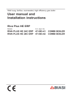
8.2Checks
nCheckthe electricalcontinuity
Fig.21 indicatestherelationship betweenthe electric
commandcomingfromthe electronic controlp.c.b.
andthepositionoftheactuatorB(brass spindle)when
theboileroperatesind.h.w.mode.
Fig.22 indicatestherelationship betweenthe electric
commandcomingfromthe electronic controlp.c.b.
andthepositionoftheactuatorB(brass spindle)when
theboileroperatesinc.h.mode.
Inbothfigurestherelationship betweenthepositionof
theactuatorandtheresistanceofthemotorwindings
(themotormustbedisconnectedfromthewiring)is
alsogiven.
B
bn=brown
bu=blue
bk=black
0V
230 V
SpindleB
notvisible
Opencircuit
9,4Kohm
bk
bn
bu
3
1
2
Fig.21 --- D.h.w.mode
B
bn=brown
bu=blue
bk=black
230 V
0V
SpindleB
visible
Opencircuit
9,4Kohm
bk
bn
bu
3
1
2
Fig.22 --- C.h.mode
8.3Removalofthe electricactuator
Warning:isolatetheboilerfromthemains
electricitysupplybeforeremovingany
coveringorcomponent.
1Removethefrontcasepanel.
2Disconnect theconnectorsC(Fig.23).
3RemovethefixingspringDandremovethe
actuatorE.
Reassembletheactuatorcarryingout there-
movaloperationsinthereverseorder.
Whenreassemblingtheactuator,refertoFig.21
ortothewiringdiagraminsection3.1forthecor-
rectwiringconnection.

Three waydivertervalve
17
D
C
E
Fig.23
8.4Removalofthedivertergroupandits
internalparts
1Removethefrontand bothsidecasepanels.
2Emptytheprimarycircuitandthed.h.wcircuitof
theboiler.
3Removethe electricactuator(see section8.3).
4RemovethefixingspringF(Fig.24)andremove
theprimarycircuitflowswitchG.
5Disconnect thec.h.temperatureprobeH.
6UnscrewtheconnectorI,thec.h.flowconnector
andthed.h.w.outletconnector.
F
G
IH
Fig.24
7Removethed.h.w.heatexchanger(see section
6.2).
8RemovetheforkJandmoveawaythepipeK
(Fig.25).
9UnscrewthescrewLandremovethediverter
group.
J
K
L
Fig.25 Rearviewoftheboiler
10 Refertothe explodedviewinFig.26 toremove
theinternalpartsofthethree waydivertervalve.
Fig.26
11 Reassemblethedivertergroupcarryingout the
removaloperationsinthereverseorder.

18
9Electronic controlp.c.b.
9.1Function
Fromotherboilerdevices....
C.h.temperatureprobeNTC
D.h.w.temperatureprobeNTC
D.h.w.flowswitch
Primarycircuitflowswitch
Roomthermostat(if fitted)
Timeswitch
Flamepresencesignal*
*fromthefull sequenceignitiondevice
OntheElectronic controlp.c.b.......
Functioncontrol*
C.h.temperatureadjustment*
D.h.w.temperatureadjustment*
Functiondip---switches
Max.c.h.gaspressureadjustment
Ignitiongaspressureadjustment
Boiler resetbutton*
*controlpanelfascia
InletInformation
Pump
Three waydivertervalve
Full sequenceignitiondevice
Modulationoperator
Applianceoperationlight*
Operation/servicelamps
Lock---outsignal lamp*
*controlpanelfascia
Outletcommand
Fig.27
ThefundamentalfunctionoftheElectronic control
p.c.b.isthatofcontrollingtheboilerinrelationtothe ex-
ternalneeds(i.e.heatingthedwellingorheatingthe
waterford.h.w.use)andoperatinginordertokeepthe
temperatureofthehydraulic circuitsconstant.
Thisisobviouslypossiblewithintheusefulpowerand
maximumworkingtemperaturelimitsforeseen.
Generally,theElectronic controlp.c.b.receivesinletin-
formationcomingfromtheboiler(thesensors)orfrom
theoutside(knobs,roomthermostat,etc.),processes
itandconsequentlyactswithoutletcommandson
othercomponentsoftheboiler(Fig.27).
9.2Selectionandadjustmentdevices
OntheElectronic controlp.c.b.severalselection,ad-
justmentand protectiondevicesarelocated.(Fig.28).
Someofthesedevicesaredirectlyaccessiblebythe
user(functioncontrol,temperatureadjustmentpoten-
tiometersetc.)othersareaccessiblebyremovingthe
servicepanelorthecontrolpanel lid.
34567
8
9
11
12
14
10
1
2
13
Fig.28
1J3connector
2J2connector
3Lock---outsignal lamp
4Boiler resetbutton
5Functioncontrol/C.h.temperatureadjustment
6D.h.w.temperatureadjustment
7Servicelamps(servicemode)
8Applianceoperationlamp(normalusemode)
9Dip---switchselectors
10 Settingjumpers
11 Ignitiongaspressureadjustment(ACC.)
12 Maximumc.h.gaspressureadjustment(RISC.)
13 J1connector
14 Fuse1,6AT
9.3Checkingthetemperature
TheElectronic controlp.c.b.makesitpossibletosepar-
atelyadjust thec.h.waterflowtemperatureand d.h.w.
outlet temperature.
Thetemperatureofthewaterisconvertedintoanelec-
tricsignalbymeansoftemperatureprobes.
/