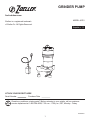
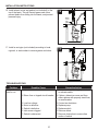
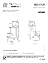
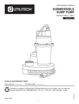
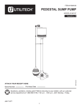
Zoeller 2701-0005 is a grinder pump designed to shred flushable solids and pump wastewater from bathrooms to a pressurized sewer main. It is suitable for long-distance (up to 750 feet) and/or high-lift (minimum of 30 feet) applications. The pump is equipped with a float switch that automatically turns it on when the water level in the basin reaches the "on" level and turns it off when the water level drops to the "off" level. The pump has a 1-1/4-inch discharge size and a maximum flow rate of 48 GPM at 0 feet of head. It is powered by a 1 HP motor and requires a 115-volt electrical connection.
Zoeller 2701-0005 is a grinder pump designed to shred flushable solids and pump wastewater from bathrooms to a pressurized sewer main. It is suitable for long-distance (up to 750 feet) and/or high-lift (minimum of 30 feet) applications. The pump is equipped with a float switch that automatically turns it on when the water level in the basin reaches the "on" level and turns it off when the water level drops to the "off" level. The pump has a 1-1/4-inch discharge size and a maximum flow rate of 48 GPM at 0 feet of head. It is powered by a 1 HP motor and requires a 115-volt electrical connection.


-
 1
1
-
 2
2
-
 3
3
-
 4
4
-
 5
5
-
 6
6
-
 7
7
-
 8
8
-
 9
9
-
 10
10
-
 11
11
-
 12
12
-
 13
13
-
 14
14
-
 15
15
-
 16
16
-
 17
17
-
 18
18
-
 19
19
-
 20
20
-
 21
21
-
 22
22
-
 23
23
-
 24
24


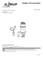
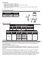
Zoeller 2701-0005 is a grinder pump designed to shred flushable solids and pump wastewater from bathrooms to a pressurized sewer main. It is suitable for long-distance (up to 750 feet) and/or high-lift (minimum of 30 feet) applications. The pump is equipped with a float switch that automatically turns it on when the water level in the basin reaches the "on" level and turns it off when the water level drops to the "off" level. The pump has a 1-1/4-inch discharge size and a maximum flow rate of 48 GPM at 0 feet of head. It is powered by a 1 HP motor and requires a 115-volt electrical connection.
Ask a question and I''ll find the answer in the document
Finding information in a document is now easier with AI
in other languages
Related papers
-
Zoeller 2701-0005 User manual
-
-
-
-
-
-
-
-
Zoeller STBS700 Operating instructions
-
Other documents
-
Everbilt HDEFR50W User guide
-
 Utilitech UT58130 Installation guide
-
 Utilitech 148010 Operating instructions
-
Little GIANT 505717 Owner's manual
-
 Utilitech 148137 Operating instructions
-
red lion RL50WA Owner's manual
-
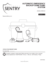 Basement Sentry STBB100 Operating instructions
-
Little GIANT 6 series Owner's manual
-
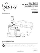 Basement Sentry 12V DC Operating instructions
-
 Utilitech 148001 Operating instructions


