4
© 2020. Todos los derechos reservados.
1
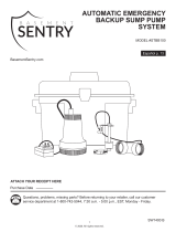
Reset:
Press for 3 seconds
SILENCE
ALARM
POWER
B Y
INTELLIGENT
SUMP
CONNECTS TO
MOBILE
DEVICES
Este LED debe estar
apagado cuando la
bomba STBS700 está en
modo AP.
Cuando el usuario
esté conectado a la
bomba STBS700 para
configurar el WiFi, el
LED parpadeará.
Cuando la bomba
STBS700 esté
conectada al router
y a la aplicación
Basement Sentry, el LED
estará continuamente
iluminado.
CONECTAR LA BOMBA STBS700 AL CONTROLADOR
LED de alimentación
verde
LED rojo de alarma
Silenciar / restablecer /
botón de enlace
Al conectar la bomba STBS700 a la aplicación Basement Sentry
mediante el WiFi integrado, el usuario puede configurar mensajes
de alerta gratuitos por correo electrónico y notificaciones “push”
de la aplicación móvil. Además, el usuario puede verificar la
disponibilidad de la bomba STBS700, silenciar alarmas de
manera remota, restablecer la unidad, ajustar las configuraciones
y modificar la forma de envío de las notificaciones. También
hay otros tipos de informaciones visuales, como el estado de la
bomba, disponibles por Internet y a través de las interfaces de la
aplicación.
Antes de comenzar:
• Descargue la aplicación Z Control®, configure la cuenta o
ingrese en zcontrolcloud.com y cree una cuenta.
• Sepa cuál es el nombre (es decir, el SSID) y la contraseña
de su router WiFi. Vuelva a verificar la contraseña para saber
cómo se escribe exactamente, incluido si tiene mayúsculas o
minúsculas.
• Verifique que su router de WiFi esté conectado a Internet.
• Verifique que su teléfono, tableta o computadora tenga WiFi
en funcionamiento, que pueda conectarse a su enrutador de
WiFi y que usted pueda estar cerca del controlador Basement
Sentry durante el proceso de instalación.
• Localice y anote la identificación del dispositivo de la bomba
STBS700 en la calcomanía plateada que se encuentra en la
parte trasera de la bomba.
Opción 1 - Utilizar la aplicación móvil (iOS y Android)
Antes de comenzar:
• Sepa cuál es el nombre (es decir, el SSID) y la contraseña
de su router WiFi. Para evitar uno de los problemas más
comunes, vuelva a verificar la contraseña para saber cómo
se escribe exactamente, incluido si tiene mayúsculas o
minúsculas.
• Verifique que su dispositivo móvil tenga WiFi en
funcionamiento con una señal fuerte cuando esté junto al
controlador Basement Sentry. Si la señal es dudosa, es
posible que el controlador no pueda mantener una conexión
estable.
• Verifique que su router WiFi esté conectado a Internet y que
esté transmitiendo una red visible y segura de 2.4 GHz.
• Se requiere una red de 2.4 GHz. Si solo ve redes de 5 GHz,
puede que tenga que iniciar sesión en su router de banda
dual para elegir transmitir las redes por separado.
• Es probable que sea necesario apagar temporalmente el
direccionamiento de banda durante la configuración.
• La red de 2.4 GHz debe utilizar seguridad WPA o WPA2. No
se aceptan redes WEP ni abiertas.
• Puede ser necesario apagar temporalmente cualquier VPN u
otros controles de red durante la configuración.
• Localice el ID de dispositivo del Basement Sentry situado en
la parte superior del controlador.
• A igual que la mayoría de los dispositivos
conectados a Internet, la conectividad WiFi
del controlador Basement Sentry debe estar
protegida por un firewall. La mayoría de los
routers cuentan con un firewall integrado.
Consulte a un profesional de redes por
preguntas específicas sobre los firewalls.
NOTA: La lista anterior también puede ayudar a
solucionar problemas de conectividad.