Page is loading ...

1
Lowes.com
ITEM #0240038, 0240036
SEWAGE PUMP
MODEL #
UT58150, UT58130
Español p. 16
Questions, problems, missing parts? Before returning to your retailer, call our customer
service department at 1-866-994-4148, 8 a.m. - 8 p.m., EST, Monday - Friday.
FW1525 0512
SUPERSEDES NEW
ATTACH YOUR RECEIPT HERE
Serial Number Purchase Date
Item #0
240038
Item #0
240036
Utilitech Pro® is a registered trademark
of LF, LLC. All Rights Reserved.
AB1253

2
Lowes.com
SAFETY INFORMATION
TABLE OF CONTENTS
Please read and understand this entire manual before attempting to assemble, operate or install the
product.
• NOTE: Pumps with the “UL” Mark and pumps with the “US” mark are tested to UL Standard
UL778. CSA certied pumps are certied to CSA Standard C22.2 No. 108. (CUS.)
Safety Information ............................................................................................................................2
Package Contents ............................................................................................................................4
Preparation .......................................................................................................................................4
General Pump Information ...............................................................................................................4
Installation Instructions .....................................................................................................................6
Specications .................................................................................................................................12
Troubleshooting ..............................................................................................................................13
Care and Maintenance ...................................................................................................................14
Warranty .........................................................................................................................................15
DANGER
ELECTRICAL SHOCK HAZARD.
Always disconnect power source before performing any work on or near the motor or its
connected load. If the power disconnect point is out-of-sight, lock it in the open position and tag it
to prevent unexpected application of power. Failure to do so could result in fatal electrical shock.
ELECTRICAL SHOCK HAZARD.
Do not handle the pump with wet hands or when standing in water as fatal electrical shock could
occur. Disconnect main power before handling unit for ANY REASON!
RISK OF ELECTRIC SHOCK.
These pumps have not been investigated for use in swimming pool areas.

3
Lowes.com
ELECTRICAL SHOCK ALERT.
To reduce the risk of electric shock, install only a circuit protected by a ground-fault circuit-interruptor
(GFCI). Make certain that the ground fault receptacle is within the reach of the pump’s power supply
cord. DO NOT USE AN EXTENSION CORD.
ELECTRICAL SHOCK ALERT.
Follow all local electrical and safety codes, as well as the National Electrical Code (NEC) and the
Occupational Safety and Health Act (OSHA).
ELECTRICAL SHOCK ALERT.
Do not kink power cable and never allow the cable to come in contact with oil, grease, hot surfaces,
chemicals, or sharp objects. Replace damaged or worn wiring cord immediately.
ELECTRICAL SHOCK ALERT.
As a safety measure, each electrical outlet should be checked for ground using an Underwriters
Laboratory Listed circuit analyzer which will indicate if the power, neutral and ground wires are
correctly connected to your outlet. If they are not, contact a licensed electrician.
ELECTRICAL SHOCK ALERT.
These pumps are supplied with a 3-prong grounded plug to help protect you against the possibility
of electrical shock. DO NOT UNDER ANY CIRCUMSTANCES REMOVE THE GROUND PIN.
ELECTRICAL SHOCK ALERT.
To reduce the risk of electric shock, install only a circuit protected by a ground-fault circuit-interruptor
(GFCI).
ELECTRICAL SHOCK ALERT.
Make sure the pump electrical supply circuit is equipped with fuses or circuit breakers of proper
capacity. A separate branch circuit is recommended, sized according the National Electrical Code
for the current shown on the pump name plate.
CHEMICAL ALERT.
This product contains chemicals known to the state of California to cause cancer and birth defects
or other reproductive harm.
WARNING
SAFETY INFORMATION
CAUTION
PRODUCT DAMAGE MAY RESULT
Make certain that the power source conforms to the requirements of your equipment.
PRODUCT DAMAGE MAY RESULT
Maximum continuous operating water temperature for standard model pumps must not exceed 104°F (40°C).

4
Lowes.com
Before beginning installation of product, make sure all parts are present. Compare parts with package
contents list. If any part is missing or damaged, do not attempt to assemble the product.
Estimated Installation Time: 2 hours
Tools Required for Assembly (not included): Adjustable wrench, hacksaw, flathead screwdriver, Phillips
screwdriver, tape measure, utility knife, pipe wrench
Part Description Quantity
A Pump 1
PREPARATION
Parts Required For Assembly (not included): sewage pump basin minimum 18 in. w x 24 in. deep,
basin cover, basin gasket, 2 in. check valve, 2 in. union, gate valve or ball valve as required by codes, 2
in. Sched 40 PVC pipe, 2-step PVC glue system (primer and sealer), cable or zip ties
PACKAGE CONTENTS
GENERAL PUMP INFORMATION
A
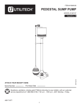
1. Sewage pumps are pumps used to remove
waste water that contains solids up to 2 in.
in diameter. The most common application is
for draining bathroom waste water to a sewer
or septic line.
Three prong
grounded
outlet
equipped
with a
ground fault
interruptor
2 in. Discharge
pipe
Upper level drainage
Cleanout
Flange
Lavatory
45°
Elbow
2 in. Check
valve
2 in. gate valve
Union
Vent pipe
Sink
Main waste
line to sewer
or septic tank
Switch
Pump
1
A

5
Lowes.com
GENERAL PUMP INFORMATION
2. These pumps are equipped with a float switch. The
pump will turn on automatically when the water level in
the basin reaches the “on” level.
On
2
Off
3
A
Item On Level Off Level
0240036 14 in. 9 in.
0240038 9-1/2 in. 5-1/2 in.
3. The pump will turn off automatically when the water
level in the basin reaches the “off” level.
A

6
Lowes.com
INSTALLATION INSTRUCTIONS
30 in.
18 in.
1. Use a basin (not included) that is at least 30 in. wide
by 18 in. deep.
1
2. Clean the basin of all debris.
2
3. Set the pump on a solid, level surface. A brick or block
(not included) may be installed under the pump to
provide a solid base.
3
A

7
Lowes.com
INSTALLATION INSTRUCTIONS
4
5
6
4. Place the pump inside the basin with the switch
positioned away from incoming water.
5. Be sure the oat switch is at least 1 in. away from the
side walls of the basin and free of any obstructions.
6. Install rigid 2 in. discharge pipe (not included) according
to local, regional and state codes.
Incoming
water
Switch
Switch
1 in.
Minimum
Discharge
Pipe
A
A
A

8
Lowes.com
INSTALLATION INSTRUCTIONS
7. Use a 2-step PVC glue system (not included) to join
pipe and any ttings needed.
8. Drill a 3/16 in. hole in the discharge pipe above the
pump discharge to prevent air lock. Water stream will
be visible from this hole when the pump is running. The
hole must be cleaned periodically.
9. Install a 2 in. union (not included) above the basin to
allow the pump to be removed for cleaning and service.
Discharge
Pipe
3/16 in.
hole
Union
7
8
9
A
A

9
Lowes.com
INSTALLATION INSTRUCTIONS
10. Install a 2 in. check valve (not included) above the
union to prevent back-ow.
11. Install a 2 in. gate valve (not included) above the check
valve as required by local, regional or state codes.
12. Connect remaining discharge pipe into main waste
line to sewer or septic tank.
Check
Valve
Gate
Valve
Main
waste line
10
11
12
A
A
A

10
Lowes.com
INSTALLATION INSTRUCTIONS
13. Attach power supply cord to discharge pipe using
cable or zip ties (not included) to allow the oat switch
to move freely.
14. Connect pump power supply cord to a receptacle
protected by a ground fault circuit interruptor (GFCI).
Cable or
Zip Ties
GFCI
protected
receptacle
13
14
A
A
15. Fill the basin with water to check operation. The pump
will start when the water level has reached the switch
“on” level.
On
15
A

11
Lowes.com
INSTALLATION INSTRUCTIONS
16. Install a basin cover and gasket (not included) on the
top of the basin. This will contain gases and odors,
prevent debris from falling into the basin and prevent
personal injury.
Basin cover
and gasket
16
A
17. Install a vent pipe (not included) according to local,
regional or state codes to remove gases and odors.
Vent pipe
17
A

12
Lowes.com
MOTOR DATA CHART
HP Phase Volts Code Letter Max Amps
Locked Rotor
Amps
1/3 1 115 H 9.5 19.5
1/2 1 115 D 9.5 19.5
PERFORMANCE
Item
Number
HP Ft. of Head Flow (GPM)
Shut Of
Head (Ft.)
Discharge
Size
0240036 1/3
5 85
20 2 in.
10 70
15 45
0240038 1/2
5 102
26 2 in.
10 85
15 63
20 37
SPECIFICATIONS

13
Lowes.com
TROUBLESHOOTING
Problem Possible Cause Corrective Action
Pump will not
start or run.
1. Water level too low. 1. Water must be at the appropriate level
to activate switch.
2. Blown fuse or tripped circuit breaker. 2. If blown, determine cause and then
either replace with properly sized fuse,
or reset breaker.
3. Low line voltage. 3. Contact an electrician.
4. Motor is defective. 4. Replace pump.
5. Switch is defective. 5. Replace switch.
6. Inlet screen clogged. 6. Remove debris.
7. Switch is obstructed. 7. Remove obstruction to ensure free
motion of switch.
Pump starts and
stops too often.
1. Water is back-flowing into basin from
discharge pipe.
1. Install check valve.
2. Switch is defective. 2. Replace switch.
3. Check valve not function properly or
leaking.
3. Be sure check valve is installed and
operating properly. Replace check
valve if necessary .
Pump shuts off
and turns on
independently
of switch (trips
thermal overload
protection.)
1. Excessive water temperature. 1. Pump should not be used for water
above
104°F (40°C).
2. Switch is defective. 2. Replace switch.
3. Switch is obstructed. 3. Remove obstruction to ensure free
motion of switch.
4. Discharge pipe is clogged. 4. Remove clog in discharge piping.
5. Low line voltage. 5. Contact an electrician.
Pump is noisy
or vibrates
excessively.
1. Worn bearings. 1. Replace pump.
2. Impeller is clogged or damaged. 2. Where applicable, remove screen
and volute, clean impeller or replace
impeller.
3. Piping attachment to building
structure too rigid or too loose.
3. Install rubber coupling (not included) to
isolate pump vibration from discharge
piping.
Pump will not
shut off.
1. Switch is defective. 1. Replace switch.
2. Switch is obstructed. 2. Remove obstruction to ensure free
motion of switch.
3. Discharge pipe is clogged. 3. Remove clog in discharge piping.
4. Water inflow exceeds pump capacity.
.
4. Re-check sizing calculations to
determine proper pump size.

14
Lowes.com
Problem Possible Cause Corrective Action
Pump operates
but delivers little
or no water.
1. Low line voltage. 1. Contact an electrician.
2. Inlet screen clogged. 2. Remove debris.
3. Broken impeller or debris in impeller
cavity.
3. Remove screen and volute, clean
impeller or replace impeller.
4. Water inflow exceeds pump capacity. 4. Re-check sizing calculations to
determine proper pump size.
5. Check valve stuck closed or installed
backwards.
5. Be sure check valve is installed and
operating properly. Replace check
valve if necessary .
6. Shut off valve closed. 6. Open shut off valve.
TROUBLESHOOTING
CARE AND MAINTENANCE
WARNING: Always disconnect pump from power
supply before handling.
Inspect and test system for proper operation at least every
three months.
1. Remove any build-up of debris from the switch or float
and check to be sure it moves freely.
On
1
2
2. Remove any debris from the basin that could interfere
with the operation of the switch.
A
A

15
Lowes.com
WARRANTY
This product is warranted for one year from the date of purchase or two years from the date of
manufacture, whichever occurs first. Subject to the conditions hereinafter set forth, the manufacturer
will repair or replace to the original consumer, any portion of the product which proves defective due
to defective materials or workmanship. To obtain warranty service, contact the dealer from whom the
product was purchased. The manufacturer retains the sole right and option to determine whether to
repair or replace defective equipment, parts or components. Damage due to conditions beyond the
control of the manufacturer is not covered by this warranty. For warranty questions or service, call
1-866-994-4148.
THIS WARRANTY WILL NOT APPLY: (a) To defects or malfunctions resulting from failure to properly
install, operate or maintain the unit in accordance with printed instructions provided; (b) to failures
resulting from abuse, accident or negligence; (c) to normal maintenance services and the parts used in
connection with such service; (d) to units which are not installed in accordance with normal applicable
local codes, ordinances and good trade practices; and (e) the unit is used for purposes other than for
what it was designed and manufactured.
RETURN OF WARRANTED COMPONENTS: Any item to be repaired or replaced under this warranty
must be returned to the manufacturer at such place as the manufacturer may designate, freight prepaid.
THE WARRANTY PROVIDED HEREIN IS IN LIEU OF ALL OTHER EXPRESS WARRANTIES,
AND MAY NOT BE EXTENDED OR MODIFIED BY ANYONE. ANY IMPLIED WARRANTIES SHALL
BE LIMITED TO THE PERIOD OF THE LIMITED WARRANTY AND THEREAFTER ALL SUCH
IMPLIED WARRANTIES ARE DISCLAIMED AND EXCLUDED. THE MANUFACTURER SHALL
NOT, UNDER ANY CIRCUMSTANCES, BE LIABLE FOR INCIDENTAL, CONSEQUENTIAL OR
SPECIAL DAMAGES, SUCH AS, BUT NOT LIMITED TO DAMAGE TO, OR LOSS OF, OTHER
PROPERTY OR EQUIPMENT, LOSS OF PROFITS, INCONVENIENCE , OR OTHER INCIDENTAL
OR CONSEQUENTIAL DAMAGES OF ANY TYPE OR NATURE. THE LIABILITY OF THE
MANUFACTURER SHALL NOT EXCEED THE PRICE OF THE PRODUCT UPON WHICH SUCH
LIABILITY IS BASED.
This warranty gives you specific legal rights, and you may have other rights which vary from state to
state. Some states do not allow limitations on duration of implied warranties or exclusion of incidental or
consequential damages, so the above limitations may not apply to you.
WARRANTY VALID IN CANADA AND MEXICO.
Printed in the U.S.A.
Utilitech & UT Design
®
is a
registered trademark of LF, LLC.
All rights reserved.
/