Page is loading ...

22-UTM-00
ECO# 104-06-MAN
I N S T A L L A T I O N
M A N U A L
TOUCHMASTER ™ SIREN/P.A. SYSTEMS
Model Number Appears on Bottom of Chassis
FS UNITROL • 1108 RAYMOND WAY • ANAHEIM, CA 92801
(714) 871-3336 • (800) 854-3375 • FAX (714) 871-3418

LIMITED WARRANTY
FS Unitrol warrants each new product to be free from defects in material and workmanship under normal use and service for
a period of five years on electronic / non-electronic parts and one year labor from date of purchase.
During this warranty period, the obligation of FS Unitrol is limited to repairing or replacing, as Unitrol may elect, any part or
parts of such product which, after examination by Unitrol, is found to be defective in material and/or workmanship.
Unitrol will provide warranty for any unit, which is delivered, transported prepaid, to the Unitrol factory for examination
when such examination reveals a defect in material and / or workmanship.
This warranty does not cover travel expenses, the cost of specialized equipment for gaining access to the product, or labor
charges for removal and re-installation of the product. Labor costs incurred outside the factory are not covered by warranty.
Lamps, flash tubes or batteries are not covered under warranty.
Wires extending from units that have been cut off flush to the faceplate, or too short for connection will be considered user
preference. They will not be replaced under warranty.
This warranty does not extend to any unit which has been subjected to abuse, misuse, improper installation or which has been
inadequately maintained, nor to units which have problems relating to service or modification at any facility other then the
Unitrol factory or authorized warranty service centers.
THERE ARE NO OTHER WARRANTIES EXPRESSED OR IMPLIED INCLUDING BUT NOT LIMITED TO ANY
IMPLIED WARRANTIES OF MERCHANTABILITY OR FITNESS FOR A PARTICULAR PURPOSE. IN NO EVENT
SHALL UNITROL BE LIABLE FOR ANY LOSS OF PROFITS OR ANY INDIRECT OR CONSEQUENTIAL
DAMAGES ARISING OUT OF ANY SUCH DEFECT IN MATERIAL OR WORKMANSHIP.
i

SECTION TITLE PAGE
I GENERAL INFORMATION …………………………3
II SPECIFICATIONS ……………………………………4
III SAFETY MESSAGE TO INSTALLERS………………5
IV INSTALLATION……………………………………… 6-8
V SAFETY MESSAGE TO OPERATORS ………………9
VI SERVICE AND MAINTENANCE ……………………10
T A B L E O F C O N T E N T S
ii

STANDARD SIREN SOUNDS ASSISTANCE
Unless otherwise requested, the Touchmaster is shipped with five (5) Technical help is available by phone 8:00 AM to 4:30PM
operational siren sounds: Pacific Standard Time, Monday through Friday, except
MAN: Manual WAIL holidays.
WAIL: WAIL plus 5-second YELP, Continuous YELP (LOCK) or
WAIL/YELP/HETRO (SWEEP) all by pressing horn ring once. (800) 854-3375 is toll free within the United States
HI-LO: Choice of 2-tone or Ultra HI-LO plus 5-second HETRO and Canada. Phone (714) 871-3336 from other
II, Continuous HETRO (LOCK) or HI-LO/HETRO/YELP (SWEEP) areas.
all by pressing horn ring once.
If it is necessary to return a unit, please observe this
procedure:
RE-PROGRAMMING SIREN SOUNDS a) Pack to prevent damage in transit.
There are five (5) sub-miniature slide switches inside the cabinet at b) Include brief description of problem.
the front-right side. Moving a switch to its c) Include name and phone number of a person
opposite position changes a sound. Switches who can be contacted in the event bench test
are numbered left to right. NOTE: HI-LO is does not reveal problem experienced in vehicle.
deleted (UOP09) on sirens for use in the
state of CA.
SWEEP WAIL Choices:
a) WAIL/YELP/Ultra HI-LO 9#5Up) COPYRIGHT FEDERAL SIGNAL CORPORATION.
b) WAIL/YELP/2-Tone HI-LO (#3 Down) All rights reserved. Touchmaster sirens are made
c) WAIL/YELP Only (#1 Down) under U.S. Patents 3,868,684 and 4,040,050 with
others pending. YELP Override, HETRO, Ultra
SWEEP HI-LO Choices: HI-LO, SWEEP and LOCK are registered trademarks
a) 2-Tone HI-LI/HETRO/YELP (#3 Down) Printed in U.S.A.
b) Ultra HI-LO/HETRO Only (#2 Down)
c) 2-Tone HI-LO/YELP Only (#3 and #4 Down)
d) Ultra HI-LO/YELP Only (#4 Down
SECTION I
GENERAL INFORMATION
Page 3

Input voltage 11-16 VDC
Standby current 0 amps
Operating current (amplifier) 7.5 amps (one 100 watt speaker)
14 amps (two 100 watt speakers)
Operating temperature range -30°C to 65°C
Frequency range 500Hz to 1650 Hz
Nominal cycle range
Wail 11 cycles per minute
Yelp 240 cycles per minute
Nominal voltage output 64V peak-to-peak (siren tones)
Audio frequency response 300 Hz to 3,000 Hz (+3 dB)
Input Impedance 4,000 ohms (nominal)
Current ratings:
Slide bar outputs (progressive):
Position 1 20 amps
Position 2 20 amps
Position 3 20 amps
Progressive total 60 amps
Toggle switches 15 amps each
SECTION II
SPECIFICATIONS
Page 4

WARNING
The lives of people depend on your safe installation
and servicing of UNITROL products. It is important to
read and follow all instructions shipped with the products.
In addition, listed below are some other important safety
instructions and precautions you should follow.
Before Installation
Qualifications
To properly install an electronic siren you must have a
good understanding of automotive electrical procedures
and systems, along with proficiency in the installation and
service of safety warning equipment.
Before Installation
Qualifications
To properly install an electronic siren you must have a
good understanding of automotive electrical procedures
and systems, along with proficiency in the installation and
service of safety warning equipment.
Sound Hazards
Your hearing and the hearing of others, in or close to your
emergency vehicle, could be damaged by loud sounds.
This can occur from short exposures to moderately loud
sounds. For hearing conservation guidance, refer to
federal, state, or local recommendations. OSHA Standard
1910.95 offers guidance on “Permissible Noise
Exposure”.
All effective sirens and horns produce loud sounds, which
may, in certain situations, cause permanent hearing loss.
You should minimize your exposure times and wear
suitable hearing protection.
During Installation
DO NOT connect this system to the vehicle battery until
ALL other electrical connections are made, mounting of
all components is complete, and you have verified that no
shorts exist.
Be sure the siren amplifier and speaker(s) in your
installation have compatible wattage ratings.
Wire size range from 10 ga (largest) to 20 ga. (smallest).
Do not use wire that is smaller than any vehicle wire
being cut
apart. Always use a size that can safely carry the load to
be operated.
application, you should ensure that the front of the speaker is clear
of any obstruction.
Install the speaker(s) in a location which provides maximum
signaling effectiveness and minimizes the sound reaching the
vehicle’s occupants.
DO NOT install equipment or route wiring or cord in the
deployment path of an air bag.
Locate the siren so the vehicle controls can be operated safely.
In order for this electronic siren to function properly, the ground
connection must be made to the NEGATIVE battery terminal.
When drilling into a vehicle structure, be sure that both sides of the
surface are clear of anything that could be damaged.
If wiring is shorted to vehicle frame, high current conductors can
cause hazardous sparks resulting in electrical fires or flying molten
metal.
SECTION III
SAFEETY MESSAGE TO INSTALLERS OF
UNITROL SYSTEMS
Sound output will be severely reduced if any objects are in
front of the speaker. If maximum sound output is required
for your application, you should ensure that he front of the
speaker is clear of any obstruction.
Install the speaker(s) in a location which provides
maximum signaling effectiveness and minimizes the sound
reaching the vehicle’s occupants.
DO NOT install equipment or route wiring or cord in the
deployment path of an air bag.
Locate the siren so the vehicle controls can be operated
safely.
In order for this electronic siren to function properly, the
ground connections must be made to the NEGATIVE
battery terminal.
When drilling into a vehicle structure, be sure that both
sides of the surface are clear of anything that could be
damaged.
If wiring is shorted to vehicle frame, high current
conductors can cause hazardous sparks resulting in
electrical fires or flying molten metal.
After Installation
After installation, test the electronic siren and speaker
system to ensure that it is operating properly.
Test all vehicle functions, including horn operation and
vehicle light systems, to ensure proper operation.
After testing is complete, provide a copy of these
instructions to the instructional staff and all operating
personnel.
File these instructions in a safe place and refer to them
when maintaining and/or reinstalling the product.
Failure to follow all safety precautions and instructions may
result in property damage, serious injury, or death to you or
others.
Page 5

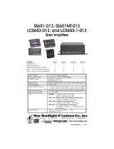
ALARM
Applying ground (-) to the ALARM terminal triggers the siren to a
distinctive 2KHz sound. This function may be used as a burglar
alarm or high-temperature alarm for K9 carriers. A motion-
detector or switches at the trunk, doors, etc. may be used for a
burglar alarm. A temperature switch (Part #UTAS) is available at
extra cost for a temperature alarm. A key switch or concealed
On/Off switch must be installed in-line with the ALARM terminal.
FOOT SWITCH
A foot switch or any manual switch may be used in lieu of, or in
addition to, the horn ring. If the switch is used alone, connect one
switch terminal to ground (-). Connect other switch terminal to
RNG. If switch is used with horn ring connections, connect one
terminal to RNG. Connect other to (-) or (+) to match horn ring
polarity.
HORN RING CONNECTIONS
Optional Use – Model TM1. MAN position of the SIREN toggle
switch supplies siren control. Connections may be made if wanted.
Mandatory – Models TM3 and TM4. Connections are
mandatory for siren controls unless a foot switch or external switch
is installed.
PANEL LIGHTING
For satisfactory lighting, it is recommended that the panel lights
(terminal #1) be connected to the vehicle light circuit as shown.
SIREN DEACTIVATION
The park kill feature of the Touchmaster uses the Neutral Safety
Switch to stop all siren sounds except P.A., Alarm, and Radio
Rebroadcast. The Neutral Safety Switch must be hooked up to the
Park Kill input using Terminal #14. A UPKM-1 must be installed
as an interface between the vehicle and the Touchmaster. (The
UPKM-1 is available at an extra cost). The UPKM-1 will protect
both the vehicle and the Touchmaster from damage caused by
transient voltages.
NOTE: The only wire connected to Terminal #14 should be the
GRAY wire of the UPKM-1. When testing this feature, put the
emergency brake on and verify siren sounds in Reverse and Drive
and no sounds in Park or Neutral.
SECTION IV
INSTALLATION
SIREN/P.A. CONNECTIONS
Page 6

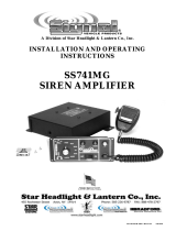
MODEL TM4
Six (6) switching functions are standard.
Functions are marked on front faceplate
(see hook – up below).
MODEL TM4-0
Same switching functions as above, but
faceplate is not marked (see hook – up
below).
MODEL TM4-1
Model has four (4) ON/OFF switches. Switching is
performed by UP toggle positions. DOWN positions are
not functional. For reference, switches are numbered one
(1) trough four (4), left to right. Numbers do not appear on
faceplate (see hook – up below).
MODIFIED MODELS
All models can be modified to accommodate special
requests. A number of modifications are available and are
designated by option numbers.
SECTION IV (CONTINUED)
ACCESSORY SWITCH CONNECTIONS
Page 7

MODEL TM1
The ON position of the Siren toggle switch may be used to
turn on a warning light or headlight flasher at the same time
the siren is turned on. Connect as shown to Terminal #17
using a 15-ampere fuse (not supplied) in line.
MODELS TM3 and TM4
Terminals #15, 16 and 17 are identified by numbers
indicating positions of the slide-bar switch that make
terminals functional. All terminals emit + 12 V. Follow
guidelines illustrated for connecting warning lights.
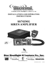
SECTION IV
(
WARNING LIGH
T
Page 8

WARNING
The lives of people depend on your safe operation of Unitrol
products. It is important to read and follow all instructions shipped
with the products. In addition, listed below are some other
important safety instructions and precautions you should follow:
Qualification
To properly use a light system you must have a good
understanding of general vehicle operation, a high
proficiency in the use of safety warning equipment and
thorough knowledge of State and Federal Uniform Traffic
Codes.
Sound Hazards
Your hearing and the hearing of others in or close to your
emergency vehicle could be damaged by loud sounds.
This can occur from short exposures to moderately loud
sounds. For hearing conservation guidance, refer to
Federal, State or local recommendations. OSHA
Standard 1910.95 offers guidance on “Permissible Noise
Exposure”.
All effective sirens and horns produce loud sounds, which
may, in certain situations, cause permanent hearing loss.
You should minimize your exposure times and wear
suitable hearing protection.
Sound Limitations
Maximum sound output will be severely reduced if any
objects are in front of the speaker. If your installation has
obstructions in front of the speaker, drive even more
cautiously. Frequently inspect the speaker to ensure that
it is clear of any obstruction, such as mud or snow, which
will reduce maximum sound output.
Signaling Limitations
Be aware that the use of your visual and audible signaling
devices does not give you the right to force your way
through traffic. Your emergency lights, siren and actions
are REQUESTING the right-of-way.
Although your warning system is operating properly, it
may not alert everyone. People may not hear, see or heed
your warning signal. You must recognize this fact and
continue driving cautiously.
Situations may occur which obstruct your warning signal
when natural or man-made objects are between your
vehicle and others, such as when you raise you hood or
trunk lid. If these situations occur, be especially careful.
The control head’s LED display simulates the light
pattern(s) being executed by the warning systems. The
display is intended ONLY as a guide and NOT as an
indication of proper warning system. Before using the
warning system, its operation should be observed from
outside the vehicle.
Driving Limitations
At the start of your shift, you should ensure that the
warning system is securely attached to the vehicle and
operating properly.
If the unique combination of emergency vehicle
equipment installed in your vehicle has resulted in the
light/siren controls being installed in a position that does
not allow you to operate them by touch only, OPERATE
CONTROLS ONLY WHILE YOUR VEHICLE IS
STOPPED.
If driving conditions require your full attention, you
should avoid operating the light/siren controls while the
vehicle is in motion.
Continuing Education
File these instructions in a safe place and refer to them
periodically. Give a copy of these instructions to new
recruits and trainees.
Failure to follow these safety precautions may result in
property damage, serious injury, or death to you, to
passengers or to others.
SECTION V
SAFETY MESSAGE TO OPERATORS OF
UNITROL SYSTEMS
Pag
e

ADJUSTING P.A. VOLUME
NO SIREN SOUNDS
If SIREN KILL feature has been connected, shift car out of
Park or Neutral before testing.
1. Check siren speaker or its wiring for a short circuit.
2. Repairing the short-circuit will automatically restore siren
operation. No damage to electronic components can result
from speaker or speaker wiring problems.
3. Remove speaker wires. Turn siren on and listen for faint siren
sound from Touchmaster cabinet. If sound can be heard,
speaker or speaker wiring is “open” (not connected).
NO HORN RING SIREN CONTROL
1. (-) or (+) polarity may be connected to the RNG terminal.
Compensation is automatic.
2. Verify that cut ends of horn ring wire have been correctly
connected to HRN (HORN) and RNG (HORN RING)
terminals. Reversed connections may result in a malfunction.
3. A relay is used in all models to transfer horn ring circuitry
(Relay #K2 at top left of top circuit board). Remove cabinet
cover and verify contact integrity.
NO MICROPHONE P.A.
1. Plug a known good microphone fully into the microphone jack
in the front faceplate.
2. If using an LM Radio Microphone Adapter, verify that correct
model has been installed for radio being used. If model is
correct, interchange adapter with another known to be
operational.
3. If above procedures are followed without results, audio input
or drive circuitry is defective.
WARNING LIGHT SWITCHING
1. Control terminals: emit +12V. Use test light or
voltmeter to check voltage at related terminals. Connect
one probe to ground.
2. If no voltage is present at tested terminals, warning light
control circuit is defective.
ACCESSORY SWITCHING
1. The release switch can be activated when ignition is on.
ASSISTANCE
Technical help is available by phone 7:00 AM to 3:30 PM Pacific
Standard Time, Monday through Friday, except holidays.
(800) 854-3375 is toll free within the United States and Canada.
Phone (714) 871-3336 from other areas.
If it is necessary to return a unit, please observe this procedure:
a) Call for RMA number.
b) Pack to prevent damage in transit.
c) Include brief description of problem and RMA No.
d) Include name and phone number of a person
who can be contacted in the event the bench test
MICROPHONE P.A.
The Volume Control switch is pre-adjusted for a
noise-canceling microphone. Other types may
“squeal”. Adjust internal volume control (behind
hole in front faceplate) with 1/8” blade screwdriver.
CAUTION: Excessive inward force will damage the
control.
1. Sit inside car: Set VOLUME on Hi. If using
radio microphone for p.a., press MIC setting of
P.A. switch. Make test count while slowly
rotating control counter-clockwise until squeal
stops.
2. Repeat test using microphone outside of car
with Volume Control in M D setting.
OUTSIDE RADIO P.A.
The Touchmaster is pre-adjusted for an input level
of 1 Vac. Higher-than-average settings of the
radio’s Volume Control will cause higher-than-
average amplification outside. Adjust radio input
level control (hole, rear right side of cabinet) with
1/8” blade screwdriver. Rotate counter-clockwise to
reduce level.
Pag
e
SECTION VI
SERVICE AND MAINTENANCE
ADJUSTMENTS & TROUBLE-SHOOTING
/