Page is loading ...

OWNER'S MANUAL
LOCK-N-LOAD®
IRON
PRESS
Instructional and troubleshooting videos for this
product are available on the Hornady website.
Item No. 085520

- 2 -
26
18
28
23
19
24
25
22
21
23
17
20 1
7
5
3
6
2
4
27
11
13 12
14
9
15
16
10
29
8
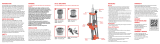
EXPLODED VIEW

- 3 -
Item
No. Part No. Qty. Description
1399600 1Iron Press Frame
2399605 1Iron Press Ram
3399602 2Iron Press Link
4399604 1Iron Press Ram Pin
5399608 1Shell Assist Collar
6390541 1Shell Holder (not included)
7390081 6E-Clip 1/2 inch
8399603 2Iron Press Pin Link
9392424 4Spring Washer
10 399601 1Iron Press Toggle
11 399617 1Toggle Spring
12 399618 110-32 Flange Screw
13 399635 1Guide Rod Toggle Spring
14 399636 1Screw SHCS 5/16-18 x 5/8
15 390657R 1Handle - Lock-N-Load® A P,™ Classic & 366
16 480003 1Ball Handle, Plastic
17 392301 1Lock-N-Load® Bushing Press
18 399619 1MP Pivot Block
19 399620 1MP Swing Arm
20 399637 1Catch Tray, Iron Press Manual Prime
21 390034 1Small Primer Seater Punch
22 390005 1Small Primer Seater Cup
23 390007 2Primer Cup Spring
24 390035 1Large Primer Seater Punch
25 390006 1Large Primer Seater Cup
26 390199 2Screw SHCS 1/4-20 x 3/4
27 390027 1Nut Jam 5/8-18
28 310165 1Pin Roll 1/8 x 3/4
29 399504 1O-Ring Buna-N 019
NO-RISK LIFETIME WARRANTY
All Hornady reloading tools and accessories are warranted against material defects and workmanship for the
life of the product. Simply stated – if it breaks, we’ll repair it or replace it at no charge (at Hornady Manufacturing
Company’s discretion).
Hornady reloading tools and accessories are warranted against defective materials and workmanship only. This
warranty is void if the product (1) has been damaged by accident or unreasonable use, neglect, improper service
or other causes not arising out of defects in material or workmanship; or (2) has been altered or repairs have been
made or attempted by other than authorized factory personnel; (3) is used commercially; or (4) has been altered or
defaced in any way.
This warranty supersedes all other warranties for Hornady products either written or oral. No other warranty is
expressed or implied.
PARTS LIST

- 4 -
11 20
18
19
5
14
2
4
15
9
8
17
16 7
3
1
10
6
12 1321 22 23
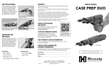
Item No. Part No. Qty. Description
1399609 1SSPF Base
2399610 1SSPF Cap
3399611 1SSPF Primer Shuttle
4399612 1SSPF Gate Pin
5392231 5Screw BHCS 8-32 x 3/8
6398322 1AP™ Primer Housing Tube
7390035 1Large Primer Seater Punch
8390006 1Large Primer Seater Cup
9399615 1Spring Stud 8-32
10 399614 2SSPF Shuttle Retainer Block
11 398318 1Primer Tube Support
12 398357 1Small Press Primer Tube
Item No. Part No. Qty. Description
13 398358 (LG) 1Large Press Primer Tube
14 390007 3Primer Cup Spring
15 399665 1SSPF Shuttle Spring
16 390034 1Small Primer Seater Punch
17 390005 1Small Primer Seater Cup
18 398319A 1Body Primer Tube Housing
19 399616 1Primer Catch Tray
20 392719 1Screw BHCS 10-32 x 3/8
21 398355 1Small Primer Pick-Up Tube
22 398356 1Large Primer Pick-Up Tube
23 398359 1Primer Follower
AUTO PRIMER FEEDER
EXPLODED VIEW

- 5 -
STEP 3
3
STEP 1
1
STEP 2
2
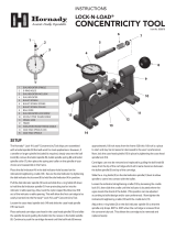
HOW LOCK-N-LOAD® WORKS
The Lock-N-Load® Reloading System is Hornady’s unique
bushing system that lets you change dies with a simple
flick of the wrist. With Lock-N-Load® technology in your
reloading press, you can stop loading, change dies, and
start loading another caliber in seconds. If you load more
than one caliber, Lock-N-Load® will dramatically speed up
your reloading efforts.
This unique technology is featured on our Lock-N-Load®
Iron Press™, Lock-N-Load Classic™ and Lock-N-Load® AP™
(Auto Progressive) reloading presses.
The Hornady Lock-N-Load® system is as easy
as 1-2-3:
1 Insert the Lock-N-Load® die bushing into the press
bushing and lock it into place with a twist. The six locking
lugs on the die and press bushings will hold it securely
in position.
2 Insert your standard die into the Lock-N-Load® Bushing.
3 Adjust the die to the proper position and lock your setting
into place with Hornady’s unique Sure-Loc™ lock ring.
To change calibers, simply twist the die counter-clockwise,
remove die and insert your next preset Lock-N-Load® die
and bushing. Because they remain locked in their
Lock-N-Load® Bushings, your dies will remain exactly as
you set them. The positive locking action of the
Lock-N-Load® Bushings holds the dies in rock solid, perfect
alignment. Once you try Lock-N-Load® from Hornady,
you’ll NEVER want to go back to your old system.
Six Locking Lugs
The combination of the six lugs and the close tolerance of
the tooling firmly grip the die bushing in place in the press
for maximum rigidity and accuracy in reloading.
Rubber O-Ring on Die Bushing
The O-ring on our die bushings gives you a better feel when
the die is inserted and holds the die tight against
the locking lugs to prevent accidental loosening. Lock-N-Load® Bushing System Patent #6,481,916
Shell Holder Platform Patent #7,395,746

- 6 -
Mount your new press securely to a solid,
level bench.
Position the press on the bench with the mounting holes
far enough back to provide firm support and still allow
clearance for the toggle.
Select a shell holder for the cases
you will be reloading.
The shell holder is retained in the recess in the top of the
ram by the shell assist collar. With a shell holder in the
ram, the collar is installed over top of the shell holder, and
its O-Ring should provide a snug fit.
NOTE: Only Hornady, RCBS, and Lee shell holders are
compatible with the shell assist collar.
Insert and adjust the sizing die.
Take note, these presses slightly cam over to allow you to
exert maximum pressure with reduced effort. Screw die
down until it is firmly against the shell holder. The sizing
die must be set when the ram is at the top of the stroke
and not after the ram has cammed over.
Priming system assembly.
A. If using the manual prime system:
Screw the proper seater punch/cup and spring for the size
primer you are using into the swing arm. Install the manual
priming arm by tightening down the two supplied ¼-20
screws (Figure 1). The arm can be left in the down position
for priming (Figure 2), or lifted up and back into a “resting”
position when not in use (Figure 3). With the ram in the up
position, install the spent primer tray by squeezing in the
arms to lock it into the press frame (Figure 4).
NOTE: Do not leave spent primer tray in press when
not in use.
NOTE: When de-priming with the manual system, the
primer arm must remain in the down position to deflect
spent primers into the catch tray.
INSTRUCTIONS
Figure 3Figure 2
Figure 1
Press Mounted
to Bench
Shell Assist
Collar
Shell Holder

- 7 -
B. If using the auto prime system:
Refer to the exploded view on page 4 for visual
reference and part names.
If your Iron Press was purchased as a kit, the main
body (base and cap) of the priming system should
be installed and set correctly from the factory. If you
purchased an Auto Prime Upgrade, install it now with
the same ¼-20 screws that were supplied for the
manual priming system:
• First, remove the primer shuttle using the steps in
Section C.
• Thread down the ¼-20 mounting screws, but do not
tighten. The priming base should still be able to move
(Figure 5).
• Insert the primer shuttle through the opening in the
front of the ram, so that it goes into the slot formed by
the cap and base (Figure 6).
• Ensure that the primer shuttle can slide freely, and
tighten down the ¼-20 screws. Keep moving the
shuttle while tightening to check for binding. If the
shuttle begins to bind, loosen the mounting screws,
adjust the position of the priming base, and
re-tighten.
• SLOWLY test the operation of the priming system
using the press handle. If resistance is felt, stop the
operation and check for binding or interference. Also,
keep in mind that the system will become smoother
once broken in.
• If the primer punch already installed on the shuttle
is not the correct size for the primers you are using,
refer to Section C for instructions on changing
punches.
C. Removing the primer shuttle/changing punches:
To ease installation of the priming system, or for the
changing of primer punches, the primer shuttle is
removed by doing the following:
• Remove the primer slide spring (Figure 7).
• Unscrew/remove the spring stud (Figure 8).
• Raise the ram to move the shuttle away from the front
of the press, and lift up on the shuttle retainer block
to remove it (Figure 9).
Figure 4
Figure 5
Figure 7
Primer Slide
Spring
Figure 6
Ram
Figure 8 Figure 9
Primer
Shuttle
Primer
Shuttle
Priming
Base
Mounting
Screw
Shuttle Retainer
Block

- 8 -
Figure 13
Primer Filler Tube
(Large or Small)
Primer Filler Tube
(Large or Small)
Primer Feed Tube
(Large or Small)
Primer Tube Support
Primer Tube Housing
Primer Filler Tube
(Large or Small)
Primer Filler Tube
(Large or Small)
Primer Feed Tube
(Large or Small)
Primer Tube Support
Primer Tube Housing
The primer shuttle should now slide out through the slot
in the front of the ram (Figure 6). When finished changing
punches, reverse the above steps to re-install the shuttle.
Once the priming system is assembled and you have
verified that it is operating correctly, insert the correct
size primer tube into the threaded housing. Be sure the
notched end of the tube goes down into the housing
(Figure 10).
Install the primer housing tube over the primer tube by
threading it onto the housing (Figure 11).
Attach the primer tube support by pushing it onto the tube
from above (Figure 12).
Install the primer catch tray by snapping it onto the cap
piece in the direction shown (Figure 13).
REMEMBER: Primers are explosives. When using either
priming system, do not try to force a primer. If something
seems to be stuck, stop and see why. Never try to force
the operation. Use extreme care when handling primers,
and always wear safety glasses.
Loading the Primer Tube
Carefully transfer the primers out of their factory
package into a Hornady Primer Turning Plate and
orientate them “shiny side up.” Then holding the Primer
Filler Tube (large or small) like a pencil bring the plastic
primer pick up tip over each primer and gently press it
over the primers. The primers will be pushed into the
filler tube one on top of another. Continue loading the
primer filler tube until you have picked up approximately
100 primers.
Make sure the cotter pin is in place; turn the Primer
Filler Tube upside down. At the top of the exposed Primer
Filler Tube, there may be several primers still held and
visible. Gently shake the tube to release the primers.
Align the Primer Filler Tube (large or small) to the Primer
Feed Tube (large or small) using the Primer Tube Support.
Remove the cotter pin from the Primer Filler Tube (large
or small) and fill the Primer Feed Tube (large or small).
The capacity of the primer tube is 100 primers.
Do not over fill the primer tube.
Insert the Primer Follower into the Primer Tube (large or
small). This will help the primers feed more reliably.
Primer Housing
Tube
Figure 11
Primer Tube Support
Figure 12
Primer Tube
Notched End
Figure 10

- 9 -
Clean, inspect and lubricate all cases
before resizing.
Using a case lube pad or Hornady® One Shot® Case Lube,
it is easy to lubricate the body portion of the bottle neck
cases. A minimum of lubricant should be used on the
neck portion since trapped lubricant may cause the
shoulder to buckle. Too little or no lubricant may easily
result in a stuck case.
Place a lubricated case in the shell holder
and pull the operating handle.
If using the manual prime system, you will need to insert
a primer before inserting a case into the shell holder. The
case can then be sized/de-primed, and re-primed on the
downward stroke of the ram.
If using the auto prime system, you should see the priming
shuttle start to move as the ram moves upwards (Figures 14
and 15). If there is tension and the shuttle does not move,
check to make sure there are no obstructions, and the
shuttle is lightly lubricated.
As the ram moves upwards and the shuttle moves to
the rear, it should release a primer from the tube and
into the priming cup. The spent primer being removed
from the case should also fall into the primer catch tray.
Adjustments to the decap pin in the size die may be
necessary to “time” the dropping of the spent primer – see
below. Ideally, the spent primer will be ejected from the
case at the very top of the ram’s stroke.
Setting Decap Timing
Primers falling too soon, missing the tray – Move decap pin
up by threading it counter-clockwise.
Primers not falling (timing too slow) – Move decap pin
down by threading it clockwise.
Check case for length and do case prep work.
After the case has been sized and de-primed, the case may
be removed from the press for case prep. First, measure
for overall length. If needed, trim the case, and chamfer/
deburr the mouth. This is also the ideal time to ream the
primer pocket if it has a military crimp.
Priming Shuttle
Priming Shuttle
Figure 14
Figure 15

- 10 -
With a fully prepared case, seat the primer.
Once your case is prepared, re-insert it into the shell
holder and continue moving the ram downwards. You
should feel some resistance when the primer seats, but
should not have to use your “weight” to seat the primer.
Remember, the force you exert on the handle is magnified
many times over by the linkage system of the press. If it
feels like you’re exerting a lot of force, stop and make sure
the primer is sitting with its anvil up (Figure 16), and that the
case’s primer pocket has enough chamfer to accept a new
primer. Some military calibers such as 5.56/223 or 7.62/308
have a staked primer. This may leave a sharp edge on the
primer pocket, and seating a new primer will be difficult.
Using a primer pocket reamer or swage tool will remove
this stake, allowing primers to be pressed in more easily.
Once a primer is seated, you may release the handle and
the ram should spring back to its neutral position. The case
may then be removed and charged with powder.
Charge prepared cases with selected powder
Weigh using either a scale, or powder measure in
conjunction with a scale. Refer to the Hornady Handbook
of Cartridge Reloading or any other reputable source for
proper loads.
Replace the sizing die with the seating die
according to instructions furnished with
the die set.
At this time you may move the manual prime arm up and
out of the way, or remove the auto priming shuttle using the
process found in Section C. Insert a case with the proper
powder charge into the shell holder, and seat a bullet.
Correct Primer Position - Anvil is Up
Incorrect Primer Position -
Primer is Upside Down
Incorrect Primer Position -
Primer is Sideways
Figure 16

- 11 -
Lock-N-Load®
Die Bushing
Part #392302
DIE BUSHINGS & PRESS BUSHINGS
Lock-N-Load® Die Bushings
Lock-N-Load® die bushings are available in convenient packs
of two, three, or ten. Put a Lock-N-Load® die bushing on all
of your favorite dies for maximum reloading efficiency.
Lock-N-Load® Die Bushings
(2-pack) No. 044094
Lock-N-Load® Die Bushings
(3-pack) No. 044093
Lock-N-Load® Die Bushings
(10-pack) No. 044096
Lock-N-Load®
Press Bushing
Part #392301
O – Ring
Part #392303
MOUNTING TEMPLATE LOCK-N-LOAD® IRON PRESS

688037-REV2 11/2016
P.O. Box 1848, Grand Island, Nebraska 68802-1848
308-382-1390 • 800-338-3220 • Fax: 308-382-5761
www.hornady.com • Hornady.com/contact_us
/