Page is loading ...

illon
recision
Products, Inc.
Manufacturers of
The World's Finest
Loading Equipment
Dillon SL 900
Instruction Manual
May 2007
SL 900, May 2007 5/21/07 11:51 AM Page 1

Table of Contents
Parts List, Schematics and Diagrams 3 - 15
SL 900 Machine Mounting Assembly 4
Upper Machine Assembly 5
Shot Container Assembly 6
Casefeeder Assembly & Parts List 7
Casefeeder Bowl Mount & Casefeed Assembly to Frame 8
Lower Machine Assembly 9
Toolhead Assembly 10
Platform Assembly 11
Primer Feed System Assembly 12
Automatic Powder Measure Assembly 13
Shot Dispenser Assembly 14
Wad Swing Arm Assembly 15
Finished Shotshell Dimensions 15
General Machine Information 16 - 17
Step-by-Step Preliminary Assembly 17 - 21
Factory Settings 22 - 23
Filling the Machine with Components – What’s First? 24 - 29
Changes and Adjustments 29 - 35
Adjusting the Collet Sizer 29
Powder Die/Funnel Adjustments 30
Adjusting the Automatic Powder System, Powder Charge Weight 30
Adjusting the Wad and Shot Station 30
Adjusting the Starter Crimp Die 31
Removing the Shot From the Machine 31
Removing the Toolhead 32
Shellplate Removal 33
Switching to Another Powder 34
The Primer System 35
Gauge Conversion - 28 ga. 36 - 40
Gauge Conversion - 20 ga. 41 - 45
Troubleshooting Section 46 - 47
Primer System 46
Casefeeder 47
General 47
Lube Points 48
Suggested Settings 49
SL 900, May 2007 5/21/07 11:51 AM Page 2

3
SL 900 Parts List
Part # Description
10641 Body Collar Adjustment Screw
10716 Primer Spring Cap
12000 Final Crimp Die
12577 1/2-20 Jam Nut
13311 Spring Pin
13418 Shellplate Bolt
13485 Mainshaft
13613 Clamp
13667 Index Pawl
13677 Ring Indexer
13700 Link Arm Shoulder Pin
13701 3/32x3/8 Dowel Pin
13738 10 Stainless Washers
13742 1/2 E-Clip
13773 8-32 Nut
13789 1/4-28 Set Screw
13791 Indexer Return Spring
13793 Collar Roller
13799 Blue Wing Nut
13801 Tinnerman Nut
13830 Mainshaft Pivot Pin
13837 1/4 E-Clip
13840 Hitch Pin Clip
13841 Nylock Nuts
13848 Bellcrank Bushing
13856 1/4 Washer SAE
13858 Rod Compression Spring
13871 Bellcrank Cube
13891 3/8 Index Ball
13895 10-24x3/8 BHCS
13896 1/4-20 x 3/8 BHCS
13901 3/8x24 Cam Pin Jam Nut
13911 1/4-20 x 2 3/4 Bolts
13923 1/4-28 Brass Tip Set Screw
13937 Slide Return Spring
13938 Pawl Spring
13943 1/4-28 Adjustment Bolt
13958 1/4 Washer
13966 1/4-28 x 3/4 SHCS
13988 1/4-20 Nuts
13989 10-24 x 5/8 SHCS
13996 10-32 Set Screw
13997 Index Ball Spring
14008 Toolhead Pins
14013 8-32x3/8 SHCS
14023 8-32 x 3/4 BHCS
14026 8-32 x 1/2 BHCS
14037 10-24 x 3/4 SHCS
14041 1/4 Wave Washer
14574 Case Insert Slide Spring Cap
14689 8-32 x 1/4 BHCS
14808 Collar Roller Bushing
14922 Link Arms
16065 650 Machine Mounts
16209 Spent Primer Cup Bracket
16221 1/4 Fender Washer
16222 1/4-20 x 11/2 Hex Bolts
16340 10-32 Nylock Nut
16667 Toolhead
16668 Toolhead Die Lockplate
16670 SL Crank
16671 Indexing Block
16672 Shotshell Chute
16675 Shellplate, 12 ga.
16676 Ejector Wire
16677 Wad Swing Arm
16678 Wad Guide Sleeve
16679 Sleeve Compression Spring
16680 1/16 x 1/2 Roll Pin
16681 Wad Guide
16682 Swing Arm Torsion Spring
16683 Case Insert Slide
16684 Slide Block
16691 Primer Transfer Arm
16692 Arm Pivot Pin
16693 Transfer Arm Spring
16694 Station Two Locator
16695 Locator Pivot Screw
16696 Locator Torsion Spring
16697 Case Insert Ramp
16698 SL Platform
16699 Spent Primer Cup
16700 Primer Seater Pin
16701 Bushing
16702 Primer Seater Spring
16707 Phish Compression Spring
16708 Casefeed Phish
16709 Camming Pin
16711 Primer Feedplate
16714 Slide/Bellcrank Spring
16717 Primer Feed Cam
16721 Tray Mounting Bracket
16723 Primer Feed Body
16724 Shot Dispenser
16725 Shot Dispenser Body
16726 Shot Drop Tube, 12 ga.
16727 Shot Dispenser Bellcrank
16731 Spring (Bellcrank Assembly)
16732 Pivot Pin
16733 Shot Bar Return Rod
16735 Shot Body Collar
16737 Collar Guide/Clamp
16738 Shot Bar
16739 Shot Bar Insert
16740 3/8-16 Half Dog Set Screw
16741 Depriming Pin
16742 SL Sizer Collet Sleeve
16743 Collet Sizer Die, 12 Ga.
16744 SL Powder Die
16746 Expander Powder Funnel
10640 Starter Crimp Die
16748 Dillon Starter Crimp Insert-1
16753 Locator Buttons
16904 1 1/2-10/32 SHCS
17123 SL 900 Casefeed Post
17124 Shot Post
17125 Dillon Bin
17126 Locator Button Spring
17130 Casefeed Sleeve, 12 Ga.
17131 Casefeed Body
17132 Primer Drop Tube
17134 Primer Bellcrank
17138 Clear Dispenser Lid
17139 Shot Dispenser Fitting
17140 Pin (Bellcrank Assembly)
17141 1/4 Hardened Washer
17142 Dispenser Top
17143 Dispenser Top Clear Lens
17146 Rubber Insert
17147 Powder Die E-Clip
17148 1 1/4 Die Lock Ring
17149 1.0 Die Lock Ring
17153 Manual
17182 SL Frame Machined
17202 Shot Fitting E-Clip
17350 Powder Bar Return Rod
17351 Die Lock Bolt
17352 Spring Button
17353 Phish Spring Socket
17354 Gate 3
17472 #8 Washer .032 Thick
17474 10-32 x 5/8 Tray Cover Screw
17476 Shot Drain
17477 Collet Sizer Spring
17479 Clear Industrial Vinyl Tubing
17509 Box
17573 Shot Drain Ext. Spring
17601 Washer .100 Thick
17603 Black Knob
17604 Clevis Pin
17637 1/4-20 x 4 1/2 Hex Head Screw
17639 .175 dia. x 1/4-20 Post
17812 Primer Seater Assembly
17815 Clear Primer Tray Cover
17816 SL Primer Slide Upper
17837 Tyton Clamp
17838 P/M Lock Link
17839 P/M Slotted Bellcrank
17843 SL 900 Foam Insert Set
17899 Stem Screw
17909 Eight Star Crimp
18086 Rod Bushing
17817 SL900 Powder Measure Assy
19201 Primer Feed System Assembly
20536 SL Casefeed Tube - white label
22134 Shot Dispenser Assy - 12 ga.
22140 1/2-1 oz. Shot Bar Assembly
22183 Roller Handle Assembly
22292 Magnetic Pick-Up Wand
97037 12 Ga. Casefeeder – 110v
97120 Red Flag
N/A Lock Link
N/A Lock Link Torsion Spring
N/A Pivot Pin
N/A Return Spring Pin
N/A Shot Bellcrank Rivet
N/A SL Bellcrank Stud
N/A Spare Parts Bag
SL 900, May 2007 5/21/07 11:51 AM Page 3

4
16065 (2)
16672
17125
16222 (4)
13856 (4)
13988 (4)
13911 (4)
13856 (4)
16221 (4)
13988(4)
Part # Description
13856 1/4 Washer SAE
13911 1/4-20 x 2 3/4 Bolts
13988 1/4-20 Nuts
16065 650 Machine Mounts
16221 1/4 Fender Washer
16222 1/4-20 x 11/2 Hex Bolts
16672 Shotshell Chute
17125 Dillon Bin
SL 900 Mounting Assembly
SL 900, May 2007 5/21/07 11:51 AM Page 4

Upper Machine Assembly
SL900 Upper Machine Assy
16676
17123
13418
*16675
13966
13667
13791
13938
13677
16699
13856
17637
13989
13989
17637
13856
13613
13988
13613
13613
13988
17124
* indicates a gauge specific part
Part # Description
13418 Shellplate Bolt
13613 Clamp
13667 Index Pawl
13677 Ring Indexer
13791 Indexer Return Spring
13856 1/4 Washer SAE
13938 Pawl Spring
13966 1/4-28 x 3/4 SHCS
13988 1/4-20 Nuts
13989 10-24 x 5/8 SHCS
16675 Shellplate, 12 ga.
16676 Ejector Wire
16699 Spent Primer Cup
17123 SL 900 Casefeed Post
17124 Shot Post
17637 1/4-20 x 4 1/2
Hex Head Screw
5
SL 900, May 2007 5/21/07 11:51 AM Page 5

6
Shot Container Assembly
16724
17202
17139
17837
17479
17202
17139
17837
Part # Description
16724 Shot Hopper
17139 Shot Dispenser Fitting
17202 Shot Fitting E-Clip
17479 Clear Industrial Vinyl Tubing
17837 Tyton Clamp
SL 900, May 2007 5/21/07 11:51 AM Page 6

7
Casefeeder Assembly
Part # Description
13400 Casefeed Bowl
13473 Casefeed Motor - 4 RPM
13539 Casefeed Cord Set
13540 Casefeed Motor Cover
13632 Casefeed Upper Disc Clutch
13685 1/4-20x5/8 BHCS
13732 10-32x1.00 SHCS
13736 Clutch
13738 SS Washers
13813 Lockwashers
13833 1/4 Terminal Connector
13903 1/4-20 Heli Coil
13912 8-32 Flat Head Screw
14025 1/8x3/4 Roll Pin
14026 Bowl/Motor Screws
14137 8x1 Cover Screw Zn.
16314 Butt. Connector
16336 Red 1/4 female Insulated Connector
16337 Blue 1/4 female Insulated Connector
17133 Shotshell Disc
17585 Zener Diode 1N5361B
17587 8x1/4 PHL. PN. Screws
17808 Casefeed Bowl Insert
97037 12 ga. Casefeed Assembly – 110v
97108 Shotshell Funnel Assembly
13779 Micro Switch
13954 4-40 Screws
14038 40-40 Nuts
16334 Lighted Rocker Switch
16704 Shotshell Funnel
17586 8x1 1/4 Funnel Screw
13813
13632
17133
13400
13736
17587
(3)
13779
14038
13954
17586
13539
13540 13912
13473
14137
16334
17808
17587
14026 (5)
13732 (4)
13738 (2) 12 Ga Plate
Assy. 17811
16704
SL 900, May 2007 5/21/07 11:51 AM Page 7

Lower Machine AssemblyCasefeeder Bowl Mount Casefeed Assembly
to Frame
13685
17124
17123
20536
16707
17353
16708
16680
17130
16680
17131
17472
14013
16709
13989 (3)
14026
Part # Description
13685 1/4x20x5/8 Screw
17123 SL 900 Casefeed Post
17124 Shot Post
20536 SL 900 Casefeed Tube - white label
Part # Description
13989 10-24 x 5/8 SHCS
14013 8-32x3/8 SHCS
14026 8-32 x 1/2 BHCS
16680 1/16 x 1/2 Roll Pin
16707 Phish Compression Spring
16708 Casefeed Phish
16709 Camming Pin
17130 Casefeed Sleeve, 12 Ga.
17131 Casefeed Body
17353 Phish Spring Socket
17472 #8 Washer .032 Thick
8
SL 900, May 2007 5/21/07 11:51 AM Page 8

Lower Machine Assembly
22183
Handle
Assembly
14922
13841
13841
17069
17918
17068
13841
13704 (2)
13789
13485
17637
13830
13700
16670
13841
14922
16671
13989
Part # Description
13485 Mainshaft
13700 Link Arm Shoulder Pin
13789 1/4-28 Set Screw
13830 Mainshaft Pivot Pin
13841 Nylock Nuts
13989 10-24 x 5/8 SHCS
14922 Link Arms
16670 SL 900 Crank
16671 Indexing Block
17182 SL 900 Frame
17637 1/4-20 x 4 1/2
Hex Head Screw
22183 Roller Handle Assembly
13704 Washer (2)
13841 Nylock Nuts
17068 Handle Bar
17069 Clip
17918 Molded Handle
17182
9
SL 900, May 2007 5/21/07 11:51 AM Page 9

*16741
*16743
16742
17351
*16748
13896
17141
16667
10640
12577
13989
13901
10185
10184
*11109
*11110
16668
17149
17148
17149
13742
17817
assembly
17147
16744
*16746
17477
17899
*17909
13895
* indicates a gauge specific part
Part # Description
10184 Crimp Die Spring
10185 Crimp Die Sleeve
11109 12 ga. Crimp Die
11110 12 ga. Seat Plug
12577 1/2-20 Jam Nut
13742 1/2 E-Clip
13895 10-24x3/8 BHCS
13896 1/4-20 x 3/8 BHCS
13901 3/8x24 Cam Pin Jam Nut
13989 10-24 x 5/8 SHCS
14008 Toolhead Pins
16667 Toolhead
16668 Toolhead Die Lockplate
16741 Depriming Pin
16742 SL Sizer Collet Sleeve
16743 Collet Sizer Die, 12 Ga.
16744 SL Powder Die
16746 Expander Powder Funnel
10640 Starter Crimp Die
16748 Dillon Starter Crimp Insert-1
17141 1/4 Hardened Washer
17147 Powder Die E-Clip
17148 1 1/4 Die Lock Ring
17149 1.0 Die Lock Ring
17351 Die Lock Bolt
17477 Collet Sizer Spring
17817 Powder Measure Assembly
17899 Stem Screw
17909 Eight Star Crimp
18140 Six Star Crimp
14008
Gauge Conversion Chart
part description 12 Ga. 20 Ga. 28 Ga.
Crimp Die 11109 10604 10615
Seat Plug 11110 10611 10621
Collet Sizer 16743 10606 10618
Decap Pin 16741 10607 10613
Powder Funnel 16746 10608 10619
Star Crimp Insert 16748 n/a n/a
Starter Crimp, 8-star 17909 18141 n/a
Starter Crimp, 6-star 18140 n/a 18142
Threaded Screw 17899 18143 18143
Shot Drop Tube 16726 10609 10616
Shot Bar Insert 16739 10187 10187
Shellplate 16675 10612 10625
Locator Button 16753 10602 10602
Locator Insert n/a 10603 10624
(yellow) (green)
Casefeed Sleeve 17130 10605 10617
Wad Guide 16681 10610 10620
(red) (yellow) (green)
This chart does not detail ALL the parts needed to
convert to another gauge. See the gauge conversion
sections of this manual.
Toolhead Assembly
10
SL 900, May 2007 5/21/07 11:51 AM Page 10

Platform Assembly
16684
16683
13937
13738
14037
16697
17944
13789
16700
16701
16702
17812
assembly
10716
13837
17639
14574
13311
16695
16696
16694
16753 (3)
17126 (3)
13891
13997
16699
16209
14689
14689
16692
16691
16693
17472
Part # Description
13311 Spring Pin
13738 10 Stainless Washers
13789 1/4-28 Set Screw
13891 3/8 Index Ball
13937 Slide Return Spring
13997 Index Ball Spring
14037 10-24 x 3/4 SHCS
14574 Case Insert Slide Spring Cap
14689 8-32 x 1/4 BHCS
16209 Spent Primer Cup Bracket
16683 Case Insert Slide
16684 Slide Block
16691 Primer Transfer Arm
16692 Arm Pivot Pin
16693 Transfer Arm Spring
16694 Station Two Locator
16695 Locator Pivot Screw
16696 Locator Torsion Spring
16697 Case Insert Ramp
16699 Spent Primer Cup
16753 Locator Buttons
17126 Locator Button Spring
17472 #8 Washer .032 Thick
17639 .175 dia. x 1/4-20 Post
17812 Primer Seater Assembly
10716 Primer Spring Cap
13837 1/4 E-Clip
16700 Primer Seater Pin
16701 Bushing
16702 Primer Seater Spring
17944 SL 900 Platform
11
SL 900, May 2007 5/21/07 11:51 AM Page 11

14026
16717
17816
16721
16723
17601
16714
14023
17134
17354
13856
17603 (3)
17474 (3)
16340
14026
17815
17472
17472
17472
13773
13773
16711
14808
13923
13793
17132
14026
17472
Dillon provides a Magnetic
Pick-Up Wand (#22292) for
picking primers out of the
primer tray, or other hard to
reach places.
Part # Description
13773 8-32 Nut
13793 Collar Roller
13856 1/4 Washer SAE
13923 1/4-28 Brass Tip Set Screw
14023 8-32 x 3/4 BHCS
14026 8-32 x 1/2 BHCS
14808 Collar Roller Bushing
16340 10-32 Nylock Nut
16714 Slide/Bellcrank Spring
16717 Primer Feed Cam
16721 Tray Mounting Bracket
Part # Description
16723 Primer Feed Body
17132 Primer Drop Tube
17134 Primer Bellcrank
17354 Gate 3
17472 #8 Washer .032 Thick
17474 10-32 x 5/8 Tray Cover Screw
17601 Washer .100 Thick
17603 Black Knob
17815 Clear Primer Tray Cover
17816 SL Primer Slide Upper
17911 Primer Stop Block (with flag)
Primer Feed System Assembly - #19201
12
SL 900, May 2007 5/21/07 11:51 AM Page 12

Automatic Powder Measure Assembly - #17817
13882
17817 SL900 Powder Measure Assy
Part # Description
13691 Powder Measure Tube Only
13793 Roller
13845 Collar Sleeve
13882 Powder Measure Lid
13921 Powder Measure Plug
13939 Body Collar Clamp
13940 Connector Body Collar
14023 8-32 x 3/4 BHCS
14037 10-24 x 3/4 SHCS (2)
14202 Powder Measure Tube Screws
14808 Collar Roller Bushing
16340 Nylon Lock Nut
16731 Spring
16732 Pivot Pin
17140 Pin
22273 Powder Dispenser Body
20063 Powder Bar Assembly, Large
13652 Powder Bar Part, Large
13853 Powder Bar Insert, Large
13893 Powder Bar Post, Large
13943 Powder Bar Bolt
13958 Powder Bar Bolt Washer
14041 Bowed Washer
Return Rod Assembly
13799 Blue Wing Nut
13801 Tinnerman Nut
13848 Bellcrank Bushing
13858 Rod Compression Spring
13871 Bellcrank Cube
14041 Bowed Washer
16904 10-32x1 1/2 SHCS
17350 Powder Bar Return Rod
17838 P/M Lock Link
17839 P/M Slotted Bellcrank
18086 Rod Bushing
22273
13691
13793
14808
13940
13845
18086
13858
13801
13799
13871
13958
13652
14041
13943
13893
13853
17839
14041
17350
16904
13939
14037
14023
16340
14202
14202
13921
13848
16732
17839
17838 17140
16731
13
Failsafe Rod
Assy. 17821
SL 900, May 2007 5/21/07 11:51 AM Page 13

Shot Dispenser Assembly - #22134, 12 gauge shown
17143
17142
14026
17146
13996
13817 *16739
16740
13958
16738
*16726
16735
10641
17552
16737
16740
14023
13738
14808
16904 13793
14041
13848
16727
13871
16733
13989
13801
13799
13858
18086
14041
13943
16725
17476
14013
13701
17573
17139
17202
17138
* indicates a gauge specific part
Part # Description
10641 Body Collar Adj. Screw
13701 3/32x3/8 Dowel Pin
13738 10 Stainless Washers
13793 Collar Roller
13799 Blue Wing Nut
13801 Tinnerman Nut
13817 10x32 Kep Nut
13848 Bellcrank Bushing
13858 Rod Compression Spring
13871 Bellcrank Cube
13943 1/4-28 Adjustment Bolt
13958 1/4 Washer
13989 10-24 x 5/8 SHCS
13996 10-32 Set Screw
14013 8-32x3/8 SHCS
14023 8-32 x 3/4 BHCS
14026 8-32 x 1/2 BHCS
14041 1/4 Wave Washer
14808 Collar Roller Bushing
16725 Shot Dispenser Body
16726 Shot Drop Tube, 12 ga.
Part # Description
16727 Shot Dispenser Bellcrank
16733 Shot Bar Return Rod
16735 Shot Body Collar
16737 Collar Guide/Clamp
16738 Shot Bar
16739 Shot Bar Insert
16740 3/8-16 half dog set screw
16904 1 1/2-10/32 SHCS
17138 Clear Dispenser Lid
17139 Shot Dispenser Fitting
17142 Shot Dispenser Top
17143 Shot Dispenser Window
17146 Rubber Insert
17202 Shot Fitting E-Clip
17476 Shot Drain
17552 Sleeve
17573 Shot Drain Ext. Spring
18086 Rod Bushing
22140 1/2-1 oz. Shot Bar
Assembly for 20 & 28 ga.
14
Failsafe Rod
Assy. 17822
SL 900, May 2007 5/21/07 11:51 AM Page 14

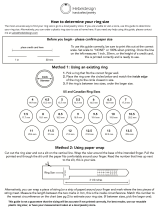
Finished Shotshell Dimensions
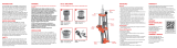
Wad Guide/Swing Arm
Assembly
#16802 - 12 gauge shown Here are some dimensions of a typical 12ga. shotshell.
Always use a quality dial caliper when measuring your
shotshells. Length may vary dependent upon shotshell
manufacturer. Dimensions shown are for maximum,
uncrimped overall length. If you find it necessary to adjust the
collet size die, try to shoot for a middle of the road measure of
the brass base.
Wad Seated Depth
When developing loads for
shotshells be aware of your “wad
seated depth.” Here’s a reference
guide for the popular wad and
shot weight used presently.
Example, if your loads currently
use a wad for 1 1/8 oz. of shot
and you decide to reduce your
shot weight and switch to 7/8 of
an ounce wads, readjust the shot
dispenser tube via the body collar
adjustment screw. Clockwise
rotation raises the shot dispenser
tube and decreases the depth the
wad is seated into the shotshell.
Counterclockwise rotation lowers
the shot dispenser tube and the
wad will get seated deeper into
the shotshell.
Finished Round Information
Your loaded round length will
vary due to loads used, type of
wads, and brand of shotshells.
We found that a majority of the
Winchester ammo loaded fell
toward 2.30 - 2.325 length.
The Remington and Federal
ammo loaded measured 2.33 -
2.350 overall length.
Always use a reputable loading
manual when reloading
shotshells.
.800-.809 Dia.
typical base
diameter
2.76 -.100
seated depth
.065
2.30 -
2.350
overall
length
16681
16678
NOTE: Periodically
lube this sleeve with
light oil.
16677
16680
13840
16682
17604
17352
16679
Wad & Shot Approx. Depth
7/8 - 1 oz. 1.12 - 1.20
1 1/8 oz. 1.30 - 1.35
1 1/4 oz. 1.45 - 1.50
13789
Part # Description
13789 1/4-28 Set Screw
13840 Hitch Pin Clip
16677 Wad Swing Arm
16678 Wad Guide Sleeve
16679 Sleeve Compression Spring
16680 1/16 x 1/2 Roll Pin
16681 Wad Guide
16682 Swing Arm Torsion Spring
17352 Spring Button
17604 Clevis Pin
15
SL 900, May 2007 5/21/07 11:51 AM Page 15

Reloading ammunition and handling powder and
primers is inherently dangerous. Just as in shooting,
accidents do happen. These accidents are
nondiscriminatory; they happen to both the novice and
the experienced reloader.
We have done everything we know how to make
your machine as safe as possible. We cannot, however,
guarantee your complete safety. To minimize your risk,
use common sense when reloading and follow these
basic rules:
Never operate the machine without ear and eye
protection on. Call our customer service department at
(800) 223-4570 for information on the wide variety of
shooting/safety glasses and hearing protection that
Dillon has to offer.
• PAY ATTENTION: Load only when you can give your
complete attention to the loading process. Don’t watch
television or try to carry on a conversation and load at
the same time. Watch the automatic systems operate
and make sure they are functioning properly. If you are
interrupted or must leave and come back to your
loading, always inspect the hulls at every station to
insure that the proper operations have been completed.
• SMOKING: Do not smoke while reloading or allow
anyone else to smoke in your reloading area. Do not
allow open flames in reloading area.
• SAFETY DEVICES: Do not remove any safety devices
from your machine or modify your machine in any way.
• MODIFICATIONS: Any modifications performed to a
machine, or the addition of any unapproved equipment
from other manufacturers will void the warranty.
• LEAD WARNING: Be sure to have proper ventilation
while handling lead components or when shooting lead
bullets. Lead is known to cause birth defects, other
reproductive harm and cancer. Wash your hands
thoroughly after handling anything made of lead.
• LOADS AND LENGTHS: Avoid maximum loads and
pressures at all times. Use only recommended loads
from manuals and information supplied by reliable
component manufacturers and suppliers. Since Dillon
Precision has no control over the components which
may be used on their equipment, no responsibility is
implied or assumed for results obtained through the use
of any such components.
Refer to a reliable loading manual for overall length
(OAL).
• QUALITY CHECKS: Every 50-100 rounds, perform
periodic quality control checks on the ammunition
being produced. Check the amount of powder being
dropped and primer supply.
• RELOADING AREA: Keep your components safely
stored. Clear your work area of loose powder, primers
and other flammables before loading.
• COMPONENTS: Never have more than one type of
powder in your reloading area at a time. The risk of a
mix-up is too great. Keep powder containers closed.
Be sure to inspect hulls prior to reloading for flaws,
cracks, splits or defects. Throw these hulls away.
Keep components and ammunition out of reach of
children.
• WINCHESTER HULLS: Please be aware that
Winchester has redesigned the AA target hull. This hull
is no longer a one-piece extruded design. Now, it is a
two-piece hull incorporating an inner reinforcing tube
which extends partway up the interior of the hull.
Winchester wads have been redesigned to work with
this new design. Additionally, some after-market wads
are now available which are compatible with the
redesigned hulls. Other wads may not be compatible
with the new AA hulls.
We suggest that you visually inspect your hulls, and
load the old and new style hulls separately, using
components appropriate to each style of hull.
• BLACK POWDER: Do not use black powder or black
powder substitutes in any Dillon powder measure.
Loading black powder cartridges requires specialized
loading equipment and techniques. Failure to do so can
result in severe injury or death.
• PRIMERS: Never force primers. If they get stuck in the
operation of the machine, disassemble it and gently
remove the obstruction.
Never attempt to deprime live primers – eventually
one will go off. When it does it will detonate the others
in the spent primer cup. Depriming live primers is the
single most dangerous thing you can do in reloading and
can cause grave injury or death.
• LOADED AMMUNITION: Properly label all of your
loaded ammunition (Date, Type of wad, primer, powder,
shot charge, etc.).
• BE PATIENT: Our loading equipment is
conservatively rated and you should have no trouble
achieving the published rates with a smooth, steady
hand. If something doesn’t seem right, stop, look and
listen. If the problem or the solution isn’t obvious, call
us. The reloading bench is no place to get into a hurry.
• REMEMBER: If your machine does not perform to
your expectations, or if you are having technical
difficulties, give us a call: (800) 223-4570 or see our
troubleshooting page online at
www.dillonprecision.com
General Machine Information
Based on our XL 650 machine frame, the SL 900
comes to you with some great automated features.
Starting from the right rear of the machine, the SL
900 features an electric casefeeder. This unit holds
approximately 80 empty hulls; enough for three boxes
of shotshells.
Turn the electric casefeeder on and the shotshell
disc (#17133) will rotate until the feed tube has filled,
then the microswitch will shut the unit off. Every
stroke of the roller handle (#22183) transfers one
empty hull from the feed tube to the shellplate via the
case insert slide ramp. Once a hull has been placed in
station one of the machine, moving the roller handle
(#22183) down will resize the brass base of the hull,
expand the mouth of the hull and remove the old
primer. NOTE: Always examine the hulls for rocks,
dirt, mud or other cases that may get stuck inside.
Also look for hulls that may appear stepped on or
flattened. Go ahead and squeeze them round again so
they won’t get stuck in the casefeed tube (#20536).
Returning the roller handle (#22183) to its full aft
position will advance the hull to station two, where a
new primer is inserted into the hull when you push
the roller handle (#22183) aft.
16
MANDATORY SAFETY MEASURES
SL 900, May 2007 5/21/07 11:51 AM Page 16

The automatic primer system holds 100 shotshell
primers. Every complete stroke of the roller handle
(#22183) will feed a primer to the hull.
The automatic powder system is also located at
station two. The hopper holds one half pound of
powder and has a fully adjustable powder bar. The
automatic powder system is hull activated. Move the
roller handle (#22183) down. When the hull contacts
the expander/powder funnel (#16746), the powder
measure is pushed up, causing the powder bar to
move and dispense one charge of powder into the
hull. Raise the roller handle (#22183) to its rest
position. The powder bar will recharge and the hull
will advance to station three.
At the third station (left, front of the machine) we
will insert the wad and meter the shot into the shell.
Move the roller handle (#22183) aft as if you are
seating a primer into the hull. You will see the wad
swing arm (#16677) tilt out, ready to accept a new
wad. With every complete stroke of the roller handle
(#22183), insert a new wad into the wad swing arm
(#16677) when it tilts out.
Move the roller handle (#22183) down. The shot
drop tube (#16726) inserts the new wad into the
empty hull and will dispense shot into the hull. Raise
the roller handle (#22183) and push aft to prime.
Hold the handle aft while you insert a wad into the
swing arm.
At station four we start the crimp in the top of the
loaded hull. It is formed and folded closed, preparing
the hull for the final crimp and seating performed in
station five.
The formed, folded top of the hull will now be
crimped and seated closed. This die is fully
adjustable. The crimp and seating depth can be
adjusted to the desired settings.
This die also has a taper crimp feature inside that
will form a tapered end to the hull. Again, move the
roller handle (#22183) down and then back up to its
rest position. The completed shotshell advances out of
the machine, down the shotshell chute (#16672) and
into the Dillon bin (#17125).
Step by Step Preliminary Assembly
1. Fasten the strong mounts (#16065) to the base
of the machine while it is lying on its side. Fig. 2
Fig. 1 - A.) Dillon Bin B.) Shotshell Chute C.) Strong Mounts D.)
Universal Mounting Kit and Hardware needed for Strong Mount
installation E.) Shot Container and Post F.) Shot Dispenser Hardware
G.) Shot Bar Return Rod and Powder Bar Return Rod
H.) SL 900 Toolhead and Frame I.) Spent Primer Cup J.) powder
measure K.) Roller Handle L.) Hardware for Shot Post and Casefeed
Post Assembly M.) Casefeed Bowl and Post N.) Clear Casefeed Tube
A.
B.
C.
D.
E.
F.
G.
H.
I.
J.
K.
L.
M.
N.
Fig. 2
17
SL 900, May 2007 5/21/07 11:51 AM Page 17

2. Lift the machine up and fasten the machine
securely to the forward edge of the bench. Fig. 3
3. Install the casefeed post (#17123) and the shot
post (#17124) to the frame of the machine using the
two long 4 1/2" bolts, 6 clamps (#13613), 2 - 1/4"
washers and 1/4-20 nuts. Fig. 4
4. Locate the shot container and place it on its
post. Fig. 5
5. Open the casefeeder box. Place the feeder on
your bench and plug it into a 110v AC outlet (220v for
European casefeeders). Place a handful of empty hulls
into the casefeeder (approximately 10). Turn the unit
on and familiarize yourself with its operation. Notice
how every time an empty hull exits the casefeeder, it
passes a microswitch. Later in the loading process, you
will see that every time the hull is next to the
microswitch the motor will shut off. Fig. 6
6. Place the casefeeder on its post. Find the clear
feed tube and place the bottom of the tube into the 12
Ga. casefeed sleeve (#17130). Align the casefeeder on
the post with the clear feed tube and snap the feed
tube into its receiver. Snug the 1/4-20 screw on the
rear of the casefeeder to secure the position of the
casefeeder. Please do not fill the clear feed tube with
empty hulls. This step will be completed later. Fig. 7
18
Fig. 3
Fig. 5
Fig. 7
Fig. 4
Fig. 6
Microswitch
SL 900, May 2007 5/21/07 11:51 AM Page 18

Be sure to secure the small, but important, screw
located at the rear of the bowl at the base. This little
screw (#13685) secures the entire bowl assembly to
the casefeed post (17123). Fig. 8
7. The powder measure (#17817) is the next item
we’ll be installing on the machine. Familiarize
yourself with its operation – every complete stroke of
the powder bar dispenses one charge of powder. The
dispenser is hull activated.
Using a 7/16” wrench, rotate the bolt located on
the end of the powder bar – counterclockwise will
reduce the powder charge weight, clockwise will
increase the powder charge weight. Fig. 9
Be sure to install the powder measure plug
(#13921) here – see arrow Fig. 9.
8. Remove the blue cap on the powder die
(#16744). Loosen the two Allen screws and place the
powder measure (#17817) on the powder die
(#16744). The clamp must lock into the groove of the
die, then secure the two Allen screws firmly. Fig. 10
9. Locate the parts bag for your machine. Enclosed
is a powder bar return rod (#17350) Fig. 11. The
powder bar return rod (#17350) must be inserted into
the bellcrank from its left side. On the bottom of the
rod is a blue wing nut (#13799), spring and white rod
bushing (#18086). Slide this end into the receiver (see
19
13685
Fig. 8
Fig. 9
Fig. 10
Fig. 11
#13921
SL 900, May 2007 5/21/07 11:51 AM Page 19

arrow Fig. 11) and snap the rod bushing (#18086)
into the platform. Thread the blue wing nut (#13799)
“up” until there’s some spring tension against the
platform – two to three turns. Do not fill the powder
measure (#17817) at this time. This will be completed
later.
10. Next we move to station three where the wad
is seated and the shot is dispensed. The Dillon shot
dispenser works similar to the powder measure
(#17817). The shot dispenser is activated by the hull
at this station. No hull – no shot. Every complete
stroke of the shot bar dispenses one charge of shot. To
adjust, loosen the bolt set screw (#16740) 1/4 of a
turn. Then use a 7/16” wrench to rotate the bolt
located on the end of the shot bar (#16738) –
counterclockwise will reduce the shot weight and
clockwise will increase the shot weight. Fig. 12
11. To complete the assembly of the shot
dispenser tube, you’ll need the following items from
the parts bag: shot bar return rod (#16733), clear shot
feed tube, two shot dispenser fittings (#17139), two
shot fitting e-clips (#17202) and two tube clamps. Fig.
13
12. Assemble the shot dispenser fittings to the
clear shot feed tube. Fig. 14 Place the tube clamps
loosely on the tube. Slide one end of the shot
dispenser fitting into the bottom of the shot hopper
(#16724 item A Fig. 13) and lock it in using one of
the shot fitting e-clips. Now, align the complete
assembly and install the other shot dispenser fitting
and e-clip into the dispenser top (#17142) and tighten
the clamps. Fig. 15
13. When installing the shot bar return rod
(#16733), use your left hand to move the lock link
down over the slot in the shot dispenser bellcrank.
Fig. 16 Now, insert the hook end of the shot bar
return rod (#16733) through both parts. On the
bottom of the rod is a blue wing nut (#13799), spring
and white rod bushing (#18086). Slide this end into
the receiver and snap the rod bushing in the platform.
Thread the blue wing nut (#13799) “up” until there is
some spring tension against the platform – two to
20
Fig. 16
Fig. 12
Fig. 14
Fig. 15
Fig. 13
A
SL 900, May 2007 5/21/07 11:51 AM Page 20
/