Page is loading ...

The following instructions provide the necessary
information for the proper operation and
preventive maintenance of the Binks MAG II
Automatic Manifold Mounted Air-Assisted
Airless HVLP Spray Gun. Please read and
understand all information in this document in
order to get the maximum performance from
your new MAG II spray gun.
In the MAG II Automatic HVLP spray gun, the
paint or other material to be sprayed is atomized;
forced through the carbide tip by the typical
1,500-3,800 psi fluid pressure (with capabilities
up to 4,000 psi/275 bar). This atomizing, plus
the final shaping air supplied by the air cap,
produces an exceptionally fine and even spray
pattern. The result of this spray pattern is an
even finish that lends itself to products that need
an exceptionally fine finish with reduced
overspray and VOC emissions.
The MAG II Automatic HVLP spray
gun uses high pressure to spray paints
and solvents. Since liquids sprayed at
high pressure can cause injuries, and
some paints and solvents can be toxic or
cause explosions and fires under certain
conditions, your safety and the safety of
others depend on your reading the
information on this Part Sheet.
If you have any questions or do not
understand the information presented,
call your nearest service representative.
NOTE
Please be sure to read the
warnings on page 2.
SPECIFICATIONS:
Max. Air Pressure: 100 psi/6.8 bar
Twist Tip HVLP: 20 psi inlet pressure is 10 psi air
cap pressure @ 5 CFM air volume
Flat Tip HVLP: 15 psi inlet pressure is 10 psi air
cap pressure @ 8 CFM air volume
Max. Fluid Pressure: 4000 psi/275 bar
Min./Max. Cylinder
Actuating Pressure:
50 psi/3.4 bar (min.),
100 psi/6.8 bar (max.)
Gun Body: Stainless Steel, Aluminum
Fluid Path: Nituff Coated Aluminum
Fluid Shut Off Type: Tungsten Carbide Seat
Fluid Inlet and
Outlet Size:
1/4" NPT(F) thread
Air Inlet Size: Atomizing Air: 1/4" NPT(F)
manifold body
Fan Air: 1/4" NPT(F)
manifold body
Cylinder Air: 1/8" NPT(F)
manifold body
Gun Weight: 1.8 lbs. (.816 kg)
Gun Mounting
Hole:
1/2" diameter
MAG II AUTOMATIC AIR-ASSISTED
AIRLESS HVLP SPRAY GUN
(U.V. AND CONVENTIONAL COATINGS)
0511-0HF0, 0511-0HT0, 0511-MHF0, 0511-MHT0
77-2949-R4.3 (6/2017) 1 / 12 www.carlisleft.com
EN
SERVICE MANUAL

INJECTION HAZARD
Spray from the gun, hose leaks, or ruptured components can inject fluid into
your body and cause extremely serious injury, including poisoning or the need
for amputation. Splashing fluid in eyes or on skin can also cause a serious injury.
• Fluid injected into the skin might look like just a cut, but is a serious injury and
should be treated as such. GET IMMEDIATE MEDICAL ATTENTION. INFORM THE
PHYSICIAN WHAT TYPE OF MATERIAL WAS INJECTED.
• Do not point the spray gun at anyone or any part of the body.
• Do not put fingers or hand over the spray tip.
• Do not stop or detect fluid leaks with a rag, hand, body or glove.
• Do not use a rag to blow back fluid. THIS IS NOT AN AIR SPRAY GUN.
• Engage the gun safety when not spraying.
• ALWAYS RELIEVE THE PRESSURE WHENEVER WORKING ON THE SPRAY GUN.
• Tighten all fluid connections before operating equipment.
• Check all hoses, tubes, and couplings daily. Replace all worn, damaged, or
loose parts immediately.
Hazardous fluids or toxic fumes can cause serious injury or death if splashed on
skin or in the eyes, swallowed or inhaled.
TOXIC FLUID HAZARD
• Know the specific hazards of the fluid you are using. This information is on the
MSDS for the material being used. Read all fluid manufacturer’s warnings.
• Store hazardous fluids in approved containers only. Dispose of all hazardous
fluids in accordance with all state, local and national guidelines.
• Wear the appropriate protective clothing, gloves, eyewear and respirator.
Equipment misuse can cause the equipment to fail, malfunction, or start
unexpectedly and result in serious injury.
EQUIPMENT MISUSE HAZARD
• This equipment is for professional use only.
• Read and understand all instructional manuals, tags, and labels before
operating equipment.
• Use the equipment only for its intended purpose. If you are unsure about its
purpose call your local Binks distributor.
• Do not alter or modify this equipment. Use only genuine Binks parts.
• Do not exceed the maximum working pressure of the lowest rated system
component. THE MAXIMUM RATING OF THE MAG II Automatic IS 4000 PSI
(275 BAR) FLUID PRESSURE. DO NOT EXCEED THE FLUID PRESSURE RATING.
• Route all hoses away from all sharp edges, moving parts, hot surfaces and
high traffic areas.
• Do not use hoses to pull the equipment.
• Use only Binks approved hoses. Do not remove spring guards from hoses,
these are on the hoses to prevent rupture from kinking at the connectors.
• Use only solvents compatible with hoses and wetted parts of the equipment
used.
• Comply with all applicable local state and national fire, electrical, and other
safety regulations.
Improper grounding, poor air ventilation, open flames, or sparks can cause a
hazardous condition and result in fire or explosion and cause serious injury.
FIRE AND EXPLOSION HAZARD
• Ground the equipment and object being sprayed.
• Provide fresh air ventilation to avoid the build up of flammable fumes from
the material being sprayed or from solvent.
• Extinguish all open flames or pilot lights in spray area.
• Electrically disconnect all equipment in the spray area.
• Keep the spray area free from all debris, including solvent rags.
• If there is any static sparking while using the equipment, STOP SPRAYING
IMMEDIATELY. Identify and correct problem.
NOISE LEVELS
• The A-weighted sound level of spray guns may exceed 85 dB(A) depending
on the setup being used. It is recommended that ear protection is worn at all
times when spraying.
WARNING
HIGH PRESSURE CAN CAUSE SERIOUS INJURY
IF EQUIPMENT IS INSTALLED OR USED
INCORRECTLY—
READ, UNDERSTAND, AND OBSERVE
ALL WARNINGS AND INSTRUCTIONS
IN THIS MANUAL.
OPERATE EQUIPMENT ONLY AFTER ALL
INSTRUCTIONS ARE CLEARLY UNDERSTOOD.
!
FLAMMABLE, EXPLOSIVE AND TOXIC VAPORS
HIGH PRESSURE SPRAY
AND HOSE LEAKS
In this part sheet, the words WARNING, CAUTION and NOTE are used to emphasize important safety information as follows:
CAUTION
Hazards or unsafe practices which could
result in minor personal injury, product
or property damage.
!
WARNING
Hazards or unsafe practices which could
result in severe personal injury, death or
substantial property damage.
!
NOTE
Important installation, operation or
maintenance information.
CA PROP
65
PROP 65 WARNING
WARNING: This product contains
chemicals known to the State of
California to cause cancer and birth
defects or other reproductive harm.
FOR FURTHER SAFETY INFORMATION REGARDING BINKS AND DEVILBISS EQUIPMENT,
SEE THE GENERAL EQUIPMENT SAFETY BOOKLET (77-5300).
IT IS THE RESPONSIBILITY OF THE EMPLOYER TO PROVIDE THIS INFORMATION TO THE OPERATOR OF THE EQUIPMENT.
NOTE
Mag II Automatic Flat Tip HVLP spray guns are
shipped with plastic Flat Tip guard installed on the
air cap. The Flat Tip guard can be removed with a
screwdriver as shown in the illustration at right.
EN
77-2949-R4.3 (6/2017)2 / 12www.carlisleft.com

MAG II AUTOMATIC HVLP SPRAY GUN SET-UP INSTRUCTIONS —
SPRAY INSTRUCTIONS
FLUID TIP SELECTION
Factors to consider in selecting a fluid tip for an air-
assisted airless spray gun include (1) the size of the parts
being sprayed; (2) the production line speed; (3) the
material flow rate and film thickness; (4) the viscosity of
the material applied; (5) the type of material applied; and
(6) the quality of atomization of the coating required.
The selection of a fluid tip necessary to perform a specific
spraying job is best determined through a combination of
experimentation and expert advice from your material
and equipment suppliers.
TO CHANGE FROM COMBINED FAN AND
ATOMIZING AIR TO SEPARATE FAN AND
ATOMIZING AIR (FLAT TIP ONLY)
1. Remove item (32) side port control by turning
counter-clockwise with a 9/16 wrench.
2. Install item (40) set screw into thread at the bottom
of tapered cavity of where the side port was.
3. Install item (41) side port plug into the upper part of
the threaded cavity of where the side port was.
SET UP FOR SPRAYING
Safe connection.
Verify that the gun is grounded per the automated
machine manufacturer’s recommendations.
Connecting gun to the material hose.
Gun should be connected by a suitable length of 3/8"
diameter material hose fitted with a the appropriate
connector that mounts to the 1/4" npt female thread of
the fluid inlet portion of the manifold. 1/4" diameter
hose is recommended for use with low viscosity
materials. (Fluid hoses of different composition are
available for special fluids.)
Connecting atomizing air to the manifold.
Guns should be connected by a suitable length of
5/16" diameter air hose fitted with a connector that
accommodates a 1/4" nps (m) fitting and should
connected the atomizing air port.
Connecting air cylinder to the manifold.
Connect 1/4" O.D. tubing to the air cylinder fitting
located on the manifold.
Controlling the material flow.
When fed from a pressure supply, an increase in
material pressure will increase the rate of flow. Correct
fluid tip size ensures correct material flow rate.
Adjusting the spray pattern.
Utilizing the adjusting side port control you can get a
30% range of pattern Adjustment. With the gun set up
to operate with remote fan air you can accommodate a
40% reduction in pattern width by increasing air
pressure to the fan port.
GENERAL SPRAY INSTRUCTIONS
1. Have at least 55-60 psi air pressure for the cylinder
operating air.
2. To reduce overspray and obtain maximum efficiency,
always spray with the lowest possible fluid/air
pressure that produces an acceptable pattern.
3. The air line to a three way valve should be as short
as possible for rapid operation.
4. All the air used in the gun should be dirt and
moisture free. This is accomplished by using
an oil and water extractor.
5. Shut off all the fluid and air lines to the gun if the
gun is to stand idle for any length of time. This is to
prevent build-up or accumulation of minute leaks in
the system from turning the gun on.
6. The distance between gun and surface should
be 6 to 12 inches depending on material and the
atomizing pressure. The material deposited should
always be even and wet. Lap each stroke over the
proceeding stroke to obtain a uniform finish.
7. Set the fluid pressure to achieve low pressure airless
pattern with tails approximately 300 to 500 psi and
will vary with fluid viscosity.
8. Open the side port control knob.
9. Set the atomizing pressure to 5 psi and increase until
the tails have been removed from the pattern and
proper atomization has been achieved. If more than
30 psi of atomizing air is required, increase fluid
pressure instead of atomizing air. If the spraying
pattern develops tails or is not uniform, gradually
increase the air pressure as necessary to develop a
uniform spraying pattern. 14 psi is the maximum inlet
pressure for HVLP flat tip air cap (20 psi max. for
HVLP twist tip cap), or use 20-30 psi inlet air
pressure for LVMP. The HVLP flat tip and twist tip
air caps consume 5-8 SCFM air at their respective
maximum inlet air pressures. The LVMP flat tip and
twist tip air caps consume 3-4 SCFM at 20-30 psi
inlet air pressure. The air is used to assist the
atomization of the coating.
10. Note: Excessive fluid/air pressure will distort the
spray pattern and produce excessive overspray. The
“hourglass” and “tails” on a spray patterns indicate
too low of fluid/air pressure or materials is too thick
or viscous. A worn or clogged tip can also cause spray
pattern distortion.
NOTE
For HVLP spray, fan adjustment feature requires 14 psi max. of
air pressure. (20 psi max. for HVLP twist tip.) For LVMP spray,
fan adjustment requires approximately 20-30 psi of air inlet
pressure. Higher fluid pressure requires higher air inlet
pressures to accommodate pattern adjustment.
NOTE
Will vary with fluid viscosity.
EN
77-2949-R4.3 (6/2017) 3 / 12 www.carlisleft.com

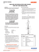
MAG II AUTOMATIC MANIFOLD MOUNTED AIR-ASSISTED HVLP SPRAY GUN
1
2
3
4
5
6
7
10
8
9
11
12
13
14
15
18
16
19
20
21A
21
22 23
25
24
23
26
27
25
28
29
25
43
44
42313240
41
45
42
33
34
35
36A
36
37
39
38
17
30
38A
OPTIONAL ITEMS
(FOR SEPARATE FAN/ATOM AIR)
TWIST TIP GUARD CAN BE
REMOVED BY REMOVING
SCREW (ITEM 38A)
LOOSENING THE RETAINING
RING AND LINING UP THE
TWIST TIP BRACE (ITEM 37) IS
REQUIRED TO INSTALL ITEM 39
TORQUE ITEM #23 TO
40 INCH/LBS
TORQUE ITEM #21 TO
10 FOOT/LBS
EN
77-2949-R4.3 (6/2017)4 / 12www.carlisleft.com

MAG II AUTOMATIC MANIFOLD MOUNTED AIR-ASSISTED HVLP SPRAY GUN
PARTS LIST
When ordering, please specify Part Number.
ITEM
NO.
NOTES PART NO. DESCRIPTION QTY.
1 54-5908 REAR CAP 1
2
●
20-6783 O-RING 1
3
▲
SPRING HOUSING 1
4
▲
NEEDLE RETURN SPRING 1
5
●
PISTON IMPACT RING 1
6 54-5332 PISTON RETURN SPRING 1
7
★
54-5318 ATOMIZING AIR VALVE 2
8
★ ●
20-6785 O-RING 2
9
★
20-6786 O-RING 2
10
★
54-5387 COLLET LOCK NUT 1
11
★
54-5317 COLLET 1
12
★
PISTON BODY 1
13
★
E-CLIP 1
14
★ ●
20-6783 O-RING 1
15
★ ●
20-6784 O-RING 1
16 54-5380 PISTON ASSEMBLY 1
17 54-5378 FLUID NEEDLE, TUNGSTEN CARBIDE 1
18 54-5376 FLUID CARTRIDGE ASSEMBLY
22 SPA-71-K5 BAFFLE PLATE (KIT OF 5) 1
23 20-6879-K4 SCREW (KIT OF 4) 4
24 54-5901 GUN HEAD 1
25
●
20-4615-5 O-RING, PTFE (KIT OF 5) 4
26 54-5902 AUTOMATIC PISTON HOUSING 1
27 54-5333-K6 RETAINING CAP SCREW (KIT OF 6) 2
28 54-5326 FLUID MANIFOLD PORT PLUG 2
29
●
20-3467 O-RING, PTFE 2
30 54-5907 MANIFOLD FLUID/AIR INLET 1
31 20-1359-1 SCREW, SQ. HEAD 1
32 54-3720 SIDE PORT ASSEMBLY 1
33 54-1835 100 MESH FILTER 1
34
●
20-5921 O-RING 1
35 54-5390 FILTER RETAINER ASSEMBLY 1
42 20-6131 PLUG, 1/4" NPT 2
43 54-4945-K10
TUBE CONNECTOR,
1/8" NPT X 1/4" TUBE (KIT OF 10)
1
44 57-13 D.M. NIPPLE, 1/4" NPT X 1/4" NPS 2
● Available as part of Rebuild Kit 54-5307.
★ 54-5380 Piston Assembly
▲ Available as part of Kit 54-5910-K.
ITEM
NO.
NOTES PART NO. DESCRIPTION QTY.
FLAT TIP COMPONENTS
19 54-5795-K
FLAT TIP HVLP AIR CAP
w/
RET. RING
1
20
■
114-XXXXX
AIRLESS TIP
(FINE FINISH 9-XXXX-F)
1
21 54-5799-K
FLUID NOZZLE
w/T.C. SEAT & GASKET
1
21
OPTIONAL
UHMW
✱
54-5811-K
FLUID NOZZLE
w/UHMWPE SEAT &
GASKET
1
21A SPA-98-K5 GASKET (PKG. OF 5 EA.) REF.
TWIST TIP COMPONENTS
36 54-5832-K
FLUID NOZZLE ASSEMBLY
(T.C.) w/GASKET
1
36
OPTIONAL
UHMW
✱
54-5833-K
UHMW FLUID NOZZLE
w/GASKET
1
36A SPA-98-K5 GASKET (PKG. OF 5 EA.) REF.
37 54-7539-K2
TWIST TIP BRACE
ASSEMBLY (KIT OF 2)
1
38
54-5924-K
TWIST TIP HVLP AIR CAP
w/
RET. RING
1
54-5925-K
TWIST TIP LVMP AIR CAP
w/
RET. RING
1
38A 54-5930 TWIST TIP GUARD SCREW 1
39
■
9-XXX-75 TWIST TIP 1
✱
OPTIONAL COMPONENTS – ORDER SEPARATELY
40 20-6748 SCREW 1
41 102-2839 SIDE PORT PLUG 1
45 72-790
D.M. NIPPLE,
HIGH PRESSURE,
1/4" NPT X 1/4" NPS
JGA-156-K10
OPTIONAL SPRING CLIP
TO RETAIN AIR CAP
(NOT SHOWN)
54-5359
OPTIONAL MANIFOLD
PLUG FOR NON-FILTER
APPLICATIONS
(NOT SHOWN)
■ See chart, page 10, for available tip sizes.
✱ Items not provided – order separately.
EN
77-2949-R4.3 (6/2017) 5 / 12 www.carlisleft.com

PROBLEM CAUSE ACTION
Fluttering Spray Pattern Insufficient fluid supply. Adjust fluid regulator or fill fluid
supply tanks.
Air in paint supply line. Check and tighten pump siphon hose
connections, bleed air from paint line.
Striping Spray – Fingers Tip partially plugged. Clean or replace tip assembly.
Irregular Pattern Fluid builds up on tip, or Clean tip.
tip partially plugged.
On defective side of pattern, air horn Clean air horn holes with solvent and
holes are plugged. a soft brush.
Pattern pushed to one side, same On defective side of pattern, air horn Clean air horn holes with solvent and
side of air cap gets dirty holes are plugged. a soft brush or toothpick.
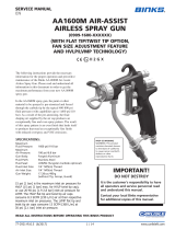
SPRAY PATTERN TROUBLESHOOTING
TROUBLESHOOTING DEFECTIVE SPRAY PATTERNS
The following procedure summarizes the steps that an
operator must immediately take when the first signs of
a defective spray pattern emerge.
1. Check the external portion of the fluid tip for material
buildup. If buildup has occurred, secure the gun
trigger safety switch and clean the gun fluid tip with
a non-metal soft brush.
2. If the spray pattern exhibits signs of tails at the top or
bottom ends of the pattern, increase the air pressure
gradually until the tails disappear.
3. If increasing air pressure does not dissipate the tails,
the fluid tip may be worn and may need to be
replaced. Another sign of the need to replace a worn
tip is a gradual decline in spraying pattern width.
4. If cleaning or replacing the fluid tip does not dissipate
the tails; the spraying defect is most likely due to the
material temperature and/or viscosity.
5. If pattern pulsation or blinking occurs, check the
pressure regulators, all downstream regulators, and
the pump. These may require further adjustment or
even repairs.
Figure 3
Correct
Pattern
Tails
Hour
Glass
Distorted
Pattern
IMPORTANT REGULATORY NOTE
The MAG II Automatic manifold mounted air-assisted automatic HVLP spray gun combines the proven efficiency of the
Binks compliant spray guns with air-assisted atomization to yield a reliable, carefully engineered compliant spray gun.
With 25' of 5/16" I.D. air hose and regulator set at only 15 p.s.i. the compliant air cap registers 10 p.s.i. of atomization
air to shape and soften the spray pattern. The MAG II Automatic manifold mounted air-assisted automatic HVLP spray gun
operates at high transfer efficiencies and fully complies with all government regulations for HVLP spray guns.
Max. Fluid Input: 4000 p.s.i.
Max. static air pressure at regulator with 25' of hose to inlet: 20 p.s.i.
Max. Dynamic Gun Inlet Air Pressure: 15 p.s.i.
Gun Body: Aluminum
Fluid Path: Nituff Coated Aluminum
EN
77-2949-R4.3 (6/2017)6 / 12www.carlisleft.com

Use 41-4458 PTFE based grease to
lubricate all o-rings and moving parts
before reassembly into the gun body.
To further protect the environment,
avoid storing solvents or solvent-soaked
wipes, such as those used for surface
preparation and cleanup, in open or
absorbent containers.
TROUBLESHOOTING
Numbers in parentheses refer to individual
items shown in the “exploded” drawing on
page 4.
CAUTION
Never use metal instruments to clean
or scrape fluid or air nozzles. These
parts have been carefully machined
and altering their shape will cause
faulty spray.
!
CAUTION
Never use lubricants containing
silicone since these lubricants can
cause finish defects.
!
WARNING
Be sure to follow all safety
precautions described on page 2
before working on the spray gun.
Never work on the spray gun until
fluid pressure has been relieved
throughout the system and the
power or air supply for the fluid
pump has been disconnected. Always
test the repaired gun for leaks with
low pressure fluid before use.
!
SERVICING/REPLACING
FLAT TIP AIR CAP, CARBIDE TIP
AND FLUID SEAT ASSEMBLY
Service symptoms (Flat Tip):
• Coating build-up on air cap or
clogged carbide tip
• Fluid seat assembly not
sealing properly
1. Depressurize the spray gun.
2. Turn retaining ring (19) counter-
clockwise and remove.
3. Remove air cap (19) and carbide tip
assembly (20) from fluid seat
assembly (21). With the air cap facing
up, apply pressure to carbide tip (20)
and remove from air cap (19).
4. Turn fluid seat assembly (21)
counterclockwise and remove.
5. Service or replace and reassemble in
reverse order.
NOTE
Carbide fluid tip needs to be
oriented properly in the air cap.
The alignment pin in the air cap is
to be properly positioned to the slot
in the carbide tip.
SERVICING/REPLACING
TWIST TIP AIR CAP, CARBIDE
TWIST TIP AND FLUID SEAT
ASSEMBLY
Service symptoms (Twist Tip):
• Coating build-up on air cap
• Clogged Twist Tip
Coating build-up:
1. Depressurize the spray gun.
2. Remove air cap (38) from the spray
gun and wash in solvent.
3. Reinstall the air cap (38).
Clogged Twist Tip:
1. Point the spray gun toward booth filter
and away from your body.
2. Rotate Twist Tip 180 degrees to
un-clog the tip.
REPLACING FLUID CARTRIDGE
AND FLUID NEEDLE
Service symptoms:
• Fluid leaking from weeps port
1. Turn rear cap (1) counterclockwise
and remove the piston return spring
from the piston housing (26) and
needle return spring (4).
2. With two 5/16" wrenches (not
supplied with gun), loosen collet
locknut (10) from collet (11).
3. Using a pair of pliers, grip collet (11)
and remove piston assembly (16).
4. Place the 3/8" deep socket (supplied
with gun) over cartridge assembly
(18) and turn counterclockwise.
5. Replace fluid needle (17) or fluid
cartridge assembly (18) and reassemble
in reverse order using the new
components as required.
NOTE
Piston assembly (16) must be
bottomed out on the piston assembly
(26) with collet (11) and locknut (10)
positioned such that the e-clip (13) is
resting against the piston assembly.
NOTE
If the piston is not positioned
correctly, the fluid-to-air timing will
not work correctly. See pictorial
view on page 8.
6. After the piston assembly has been
positioned properly, tighten locknut
(10) to collet (11) “wrench tight”.
REPLACING O-RINGS ON
PISTON ASSEMBLY
Service symptoms:
• Atomizing air not cycling off
• Air not actuating fluid
1. Turn end cap (1) counterclockwise
and remove the piston return spring
from the piston housing (26) and
needle return spring (4).
2. With two 5/16" wrenches (not
supplied with gun), loosen collet
locknut (10) from collet (11).
3. Using a pair of pliers, grip collet (11)
and remove piston assembly (16).
4. Replace o-rings (8, 9, 14 & 15) using
Standard Piston O-ring Repair Kit
54-5303 or High Performance Piston
O-ring Repair Kit 54-5307.
5. Apply 41-4458 PTFE-based lubricant
provided in the o-ring repair kits to
o-rings and reassemble in reverse
order.
NOTE
Piston assembly (16) must be
bottomed out on the piston housing
(26) with collet (11) and locknut (10)
positioned such that the e-clip (13) is
resting against the piston assembly.
NOTE
If the piston is not positioned
correctly, the fluid-to-air timing will
not work correctly. See pictorial
view on page 8.
6. After the piston assembly has been
positioned properly, tighten locknut
(10) to collet (11) “wrench tight”.
SERVICING/REPLACING FILTER
Service symptoms:
• Fluid tip clogging or restriction
in fluid flow
1. Using a 3/4" inch wrench, turn filter
retainer (35) counterclockwise and
remove.
2. Place a standard screwdriver inside the
cavity where the filter (33) is housed and
dislodge it by lifting up with the
screwdriver. Remove filter and clean or
replace as required. Most of the time you
can dislodge the filter using your finger.
3. Reassemble in reverse order.
NOTE
O-ring (34) does not require
replacement when servicing filter.
Replace o-ring (34) if a leak
develops around filter retainer (35).
MAG II AUTOMATIC MANIFOLD MOUNTED AIR-ASSISTED AIRLESS HVLP SPRAY GUN
MAINTENANCE/TROUBLESHOOTING AND SERVICE INSTRUCTIONS
NOTE
Disassemble spray gun and remove
all o-rings before immersing gun in
or subjecting it to a flood-wash of
cleaning solvent. Contact with solvents
may induce o-ring swelling beyond
their specification sizes and cause
subsequent malfunction of the gun.
(continued on page 8)
EN
77-2949-R4.3 (6/2017) 7 / 12 www.carlisleft.com

SPRAY GUN
SPRAY GUN
CYLINDER
AIR SOLENOID
(3-WAY)
ATOMIZING AIR
REGULATOR
PLUG
FLUID SUPPLY
FILTER
CYLINDER AIR
ATOMIZING AIR
CYLINDER
AIR SOLENOID
(3-WAY)
FLUID SUPPLY
FILTER
ATOMIZING AIR
CYLINDER AIR
FAN AIR
FAN AIR
REGULATOR
ATOMIZING AIR
REGULATOR
FLUID RETURN
FLUID RETURN
GROUND
GROUND
MAG II AUTOMATIC HVLP
PISTON POSITIONING
Install piston assembly into piston
housing. Be sure all o-rings are
properly lubricated with 41-4458
PTFE-based lubricant provided
with o-ring repair kits.
Piston assembly must be
bottomed out in the piston
housing (approximately 5/8" from
the top of the piston housing).
Lift the collet until it stops and
hold in an upright position while
inserting a 5/16" wrench onto
the collet.
Insert and tighten the collet
locknut using a second 5/16"
wrench and “wrench tighten”.
If properly assembled, bottom
of collet should be 3/16" from
the top of the piston assembly.
Piston Assembly
Piston Housing
Piston Assembly
Collet
Collet Locknut
3/16"
MAG II AUTOMATIC HVLP HOSE HOOK-UPS
SPRAY GUN
SPRAY GUN
CYLINDER
AIR SOLENOID
(3-WAY)
ATOMIZING AIR
REGULATOR
PLUG
FLUID SUPPLY
FILTER
CYLINDER AIR
ATOMIZING AIR
CYLINDER
AIR SOLENOID
(3-WAY)
FLUID SUPPLY
FILTER
ATOMIZING AIR
CYLINDER AIR
FAN AIR
FAN AIR
REGULATOR
ATOMIZING AIR
REGULATOR
FLUID RETURN
FLUID RETURN
GROUND
GROUND
Hose Hook-Up with Atomizing/Fan Air COMBINED
Hose Hook-Up with Atomizing/Fan Air SEPARATED
(FOR FLAT TIP APPLICATIONS ONLY)
NOTE
The gun will leak air if the piston is not
adjusted correctly.
REMOVING/REPLACING GUN
ASSEMBLY MODULE ONLY
FROM INLET MANIFOLD
ASSEMBLY
1. Using a 9/64" Allen wrench (supplied
with gun), turn retaining cap screw
(23) counter-clockwise typical
4 places and remove gun sub module.
2. Mount the new gun module, tightening
the retaining screws (23) “wrench tight”.
This will allow fluid and air passages
to seal with no contamination.
NOTE
O-rings (25 & 29) must be replaced
when replacing gun sub module.
MAINTENANCE/TROUBLESHOOTING AND SERVICE
INSTRUCTIONS (CONTINUED)
EN
77-2949-R4.3 (6/2017)8 / 12www.carlisleft.com

MAG II AUTOMATIC HVLP MOUNTING SPECIFICATIONS
(FLAT TIP)
1.750
1/4" O.D. TUBE X
1/8"NPT FITTING
CYLINDER AIR
SIDE PORT
AIR FAN
ADJUSTMENT
1/4"NPT(F)
FAN AIR INLET
1/4"NPT(F)
ATOMIZING AIR INLET
1/2" DIA HOLE
FOR GUN MOUNTING ROD
SET SCREW FOR ROD MOUNT OR
SINGLE BOLT ADAPTER MOUNT
1/4"NPT(F) FLUID
INLET TYPICAL
BOTH SIDES
5 13/16"
.966
1.826
2.700
.735
1.470
3.158
2.306
.402
.402
8-32 X 3/16"
DEEP TYPICAL 8 PLACES
PISTON VENT AND FLUID
BY-PASS WEEP PORT
PLATE MOUNTING SPECIFICATIONS
1.201
1.282
1.375
MAG II AUTOMATIC HVLP MOUNTING SPECIFICATIONS
(WITH TWIST TIP)
1.750
1/4" O.D. TUBE X
1/8"NPT FITTING
CYLINDER AIR
SIDE PORT
AIR FAN
ADJUSTMENT
1/4"NPT(F)
FAN AIR INLET
1/4"NPT(F)
ATOMIZING AIR INLET
1/2" DIA HOLE
FOR GUN MOUNTING ROD
SET SCREW FOR ROD MOUNT OR
SINGLE BOLT ADAPTER MOUNT
1/4"NPT(F) FLUID
INLET TYPICAL
BOTH SIDES
6 7/8"
.966
1.826
2.700
.704
1.470
3.158
2.306
.402
.402
8-32 X 3/16"
DEEP TYPICAL 8 PLACES
PISTON VENT AND FLUID
BY-PASS WEEP PORT
PLATE MOUNTING SPECIFICATIONS
1.201
1.282
1.375
1.308
.201
M5 THREAD
1.308
.201
M5 THREAD
EN
77-2949-R4.3 (6/2017) 9 / 12 www.carlisleft.com

MAG II AUTOMATIC MANIFOLD MOUNTED AIR-ASSISTED HVLP SPRAY GUN
STANDARD FLAT TIP SELECTION CHARTS
GPM
FAN CAPACITY
WIDTH @500 PSI
PART NUMBER DESCRIPTION ORIFICE (IN.) WATER
114-00702 TIP ASSEMBLY .007 2 .028
114-00704 TIP ASSEMBLY .007 4 .028
114-00706 TIP ASSEMBLY .007 6 .028
114-00708 TIP ASSEMBLY .007 8 .028
114-00902 TIP ASSEMBLY .009 2 .039
114-00906 TIP ASSEMBLY .009 6 .039
114-00908 TIP ASSEMBLY .009 8 .039
114-00910 TIP ASSEMBLY .009 10 .039
114-00912 TIP ASSEMBLY .009 12 .039
114-01104 TIP ASSEMBLY .011 4 .060
114-01106 TIP ASSEMBLY .011 6 .060
114-01108 TIP ASSEMBLY .011 8 .060
114-01110 TIP ASSEMBLY .011 10 .060
114-01112 TIP ASSEMBLY .011 12 .060
114-01114 TIP ASSEMBLY .011 14 .060
114-01304 TIP ASSEMBLY .013 4 .090
114-01306 TIP ASSEMBLY .013 6 .090
114-01308 TIP ASSEMBLY .013 8 .090
114-01310 TIP ASSEMBLY .013 10 .090
114-01312 TIP ASSEMBLY .013 12 .090
114-01314 TIP ASSEMBLY .013 14 .090
114-01316 TIP ASSEMBLY .013 16 .090
114-01506 TIP ASSEMBLY .015 6 .120
114-01508 TIP ASSEMBLY .015 8 .120
114-01510 TIP ASSEMBLY .015 10 .120
114-01512 TIP ASSEMBLY .015 12 .120
114-01514 TIP ASSEMBLY .015 14 .120
114-01516 TIP ASSEMBLY .015 16 .120
114-01518 TIP ASSEMBLY .015 18 .120
114-01706 TIP ASSEMBLY .017 6 .160
114-01708 TIP ASSEMBLY .017 8 .160
114-01710 TIP ASSEMBLY .017 10 .160
114-01712 TIP ASSEMBLY .017 12 .160
114-01714 TIP ASSEMBLY .017 14 .160
114-01716 TIP ASSEMBLY .017 16 .160
114-01718 TIP ASSEMBLY .017 18 .160
114-01906 TIP ASSEMBLY .019 6 .190
114-01908 TIP ASSEMBLY .019 8 .190
114-01910 TIP ASSEMBLY .019 10 .190
114-01912 TIP ASSEMBLY .019 12 .190
114-01914 TIP ASSEMBLY .019 14 .190
114-01916 TIP ASSEMBLY .019 16 .190
114-01918 TIP ASSEMBLY .019 18 .190
114-02110 TIP ASSEMBLY .021 10 .240
114-02112 TIP ASSEMBLY .021 12 .240
114-02114 TIP ASSEMBLY .021 14 .240
114-02116 TIP ASSEMBLY .021 16 .240
114-02118 TIP ASSEMBLY .021 18 .240
114-02410 TIP ASSEMBLY .024 10 .310
114-02412 TIP ASSEMBLY .024 12 .310
114-02414 TIP ASSEMBLY .024 14 .310
114-02416 TIP ASSEMBLY .024 16 .310
114-02418 TIP ASSEMBLY .024 18 .310
114-02710 TIP ASSEMBLY .027 10 .385
114-02712 TIP ASSEMBLY .027 12 .385
114-02714 TIP ASSEMBLY .027 14 .385
114-02716 TIP ASSEMBLY .027 16 .385
114-02718 TIP ASSEMBLY .027 18 .385
TWIST TIP SELECTION CHARTS
FAN GPM
WIDTH CAPACITY
PART NUMBER DESCRIPTION ORIFICE (IN.) @2200 PSI
9-307-75 TWIST TIP 0.007 6 0.05
9-309-75 TWIST TIP 0.009 6 0.09
9-409-75 TWIST TIP 0.009 8 0.09
9-509-75 TWIST TIP 0.009 10 0.09
9-211-75 TWIST TIP 0.011 4 0.12
9-311-75 TWIST TIP 0.011 6 0.12
9-411-75 TWIST TIP 0.011 8 0.12
9-511-75 TWIST TIP 0.011 10 0.12
9-611-75 TWIST TIP 0.011 12 0.12
9-213-75 TWIST TIP 0.013 4 0.18
9-313-75 TWIST TIP 0.013 6 0.18
9-413-75 TWIST TIP 0.013 8 0.18
9-513-75 TWIST TIP 0.013 10 0.18
9-613-75 TWIST TIP 0.013 12 0.18
9-713-75 TWIST TIP 0.013 14 0.18
9-215-75 TWIST TIP 0.015 4 0.24
9-315-75 TWIST TIP 0.015 6 0.24
9-415-75 TWIST TIP 0.015 8 0.24
9-515-75 TWIST TIP 0.015 10 0.24
9-615-75 TWIST TIP 0.015 12 0.24
9-715-75 TWIST TIP 0.015 14 0.24
9-317-75 TWIST TIP 0.017 6 0.31
9-417-75 TWIST TIP 0.017 8 0.31
9-517-75 TWIST TIP 0.017 10 0.31
9-617-75 TWIST TIP 0.017 12 0.31
9-717-75 TWIST TIP 0.017 14 0.31
9-419-75 TWIST TIP 0.019 8 0.38
9-519-75 TWIST TIP 0.019 10 0.38
9-619-75 TWIST TIP 0.019 12 0.38
9-521-75 TWIST TIP 0.021 10 0.47
9-621-75 TWIST TIP 0.021 12 0.47
9-523-75 TWIST TIP 0.023 10 0.57
9-623-75 TWIST TIP 0.023 12 0.57
9-525-75 TWIST TIP 0.025 10 0.67
9-625-75 TWIST TIP 0.025 12 0.67
9-627-75 TWIST TIP 0.027 12 0.74
9-435-75 TWIST TIP 0.035 8 1.31
9-631-75 TWIST TIP 0.031 12 1.03
9-635-75 TWIST TIP 0.035 12 1.31
Fan width based on 2200 PSI with latex
paint 12" from surface. Actual results may
vary, depending on material viscosity.
Fan width based on 1000 PSI with water
12" from surface. Actual results may
vary, depending on material viscosity.
FINE FINISH FLAT TIP SELECTION CHARTS
GPM
FAN CAPACITY
WIDTH @500 PSI
PART NUMBER DESCRIPTION ORIFICE (IN.) WATER
9-0909-F FINE FINISH TIP 0.009 9 0.039
9-0911-F FINE FINISH TIP 0.009 11 0.039
9-1109-F FINE FINISH TIP 0.011 9 0.06
9-1111-F FINE FINISH TIP 0.011 11 0.06
9-1113-F FINE FINISH TIP 0.011 13 0.06
9-1115-F FINE FINISH TIP 0.011 15 0.06
9-1309-F FINE FINISH TIP 0.013 9 0.09
9-1311-F FINE FINISH TIP 0.013 11 0.09
9-1313-F FINE FINISH TIP 0.013 13 0.09
9-1315-F FINE FINISH TIP 0.013 15 0.09
9-1509-F FINE FINISH TIP 0.015 9 0.12
9-1511-F FINE FINISH TIP 0.015 11 0.12
9-1513-F FINE FINISH TIP 0.015 13 0.12
9-1515-F FINE FINISH TIP 0.015 15 0.12
9-1517-F FINE FINISH TIP 0.015 17 0.12
9-1709-F FINE FINISH TIP 0.017 9 0.16
9-1711-F FINE FINISH TIP 0.017 11 0.16
9-1713-F FINE FINISH TIP 0.017 13 0.16
9-1715-F FINE FINISH TIP 0.017 15 0.16
9-1717-F FINE FINISH TIP 0.017 17 0.16
Fan width based on 1000 PSI with water
12" from surface. Actual results may
vary, depending on material viscosity.
TWIST TIP NOTE
When switching from flat tip to twist tip, increase pattern
size by 2 inches and use air adjustment to turn down to
desired size.
EN
77-2949-R4.3 (6/2017)10 / 12www.carlisleft.com

HOW TO ORDER THE MAG II
AUTOMATIC SPRAY GUN WITH MANIFOLD
0511-MHF0
MAG II Automatic HVLP Spray Gun WITH MANIFOLD,
(Flat Tip)
0511-MHT0
MAG II Automatic HVLP Spray Gun WITH MANIFOLD,
(Twist Tip)
Spray tips must be ordered separately. Use the spray tip selection chart to
determine orifice size and fan size required.
REPAIR, CLEANING & MOUNTING KITS
PART NO. DESCRIPTION
54-4994 Cleaning Kit: includes one standard stiff nylon
pipe cleaning brush, full-size nylon brush, tip
cleaner, and Binks Gunners Mate Lubricant
54-5303 Standard Performance Seal Kit (optional)
54-5396 Piston Collet Repair Kit
54-5307 High Performance Seal Kit (standard in gun)
54-5399 Single Bolt CEFLA Adapter Kit
FLUID FILTER
PART NO. DESCRIPTION
54-1835 100 Mesh Filter Screen
ACCESSORIES
PART NO. DESCRIPTION
41-4458 PTFE O-ring Lube
54-5932-K Twist Tip HVLP Air Cap Test Kit
54-5837-K Flat Tip HVLP Air Cap Test Kit
54-380 Gun Mounting Bracket
54-5305 MA2 Adapter Plate Kit (Kremlin mounting)
MAG II AUTOMATIC MANIFOLD MOUNTED AIR-ASSISTED HVLP SPRAY GUN
FLAT TIP COMPONENTS
PART NO. DESCRIPTION
54-5799-K FLUID SEAT, TUNGSTEN CARBIDE w/GASKET
54-5811-K FLUID SEAT, UHMPE w/GASKET (OPTIONAL)
SPA-98-K5 GASKET (KIT OF 5)
114-XXXXX FLAT TIP
9-XXXX-F FLAT TIP (FINE FINISH)
54-5795-K FLAT TIP HVLP AIRCAP KIT
54-5797-K FLAT TIP LVMP AIRCAP KIT
54-5852 RETAINING RING
54-5794 FLAT TIP GUARD
TWIST TIP COMPONENTS
PART NO. DESCRIPTION
54-5832-K TWIST TIP FLUID SEAT, TUNGSTEN CARBIDE
w/GASKET
54-5833-K TWIST TIP FLUID SEAT, UHMPE w/GASKET
9-XXX-75 TWIST TIP
54-7539-K2 TWIST TIP BRACE (KIT OF 2)
54-5924-K TWIST TIP HVLP AIRCAP KIT
54-5925-K TWIST TIP LVMP AIRCAP KIT
54-5928 RETAINING RING
54-5921 TWIST TIP GUARD
SPA-98-K5 GASKET (KIT OF 5)
HOW TO ORDER THE MAG II
AUTOMATIC SPRAY GUN WITHOUT MANIFOLD
0511-0HF0
MAG II Automatic HVLP Spray Gun WITHOUT MANIFOLD,
(Flat Tip)
0511-0HT0
MAG II Automatic HVLP Spray Gun WITHOUT MANIFOLD,
(Twist Tip)
Spray tips must be ordered separately. Use the spray tip selection chart to
determine orifice size and fan size required.
0511 – __ – H – __ – 0
MAG II SPRAY GUN 0 = NO MANIFOLD HVLP F = FLAT TIP
M = WITH MANIFOLD T = TWIST TIP
MAG II DESIGNATION
EN
77-2949-R4.3 (6/2017) 11 / 12 www.carlisleft.com

EN
77-2949-R4.3 (6/2017)12 / 12www.carlisleft.com
WARRANTY POLICY
Binks products are covered by Carlisle Fluid Technologies one year materials and workmanship
limited warranty. The use of any parts or accessories, from a source other than
Carlisle Fluid Technologies, will void all warranties. For specic warranty information please contact
the closest Carlisle Fluid Technologies location listed below.
Binks is part of Carlisle Fluid Technologies, a global leader in innovative nishing technologies.
For technical assistance or to locate an authorized distributor, contact one of our international sales
and customer support locations.
USA/Canada
Tel: 1-888-992-4657
Fax: 1-888-246-5732
United Kingdom
Tel: +44 (0)1202 571 111
Fax: +44 (0)1202 573 488
China
Tel: +8621-3373 0108
Fax: +8621-3373 0308
Mexico
Tel: +52 55 5321 2300
Fax: +52 55 5310 4790
Japan
Tel: +81 45 785 6421
Fax: +81 45 785 6517
Brazil
Tel: +55 11 5641 2776
Fax: +55 11 5641 1256
Germany
Tel: +49 (0) 6074 403 1
Fax: +49 (0) 6074 403 281
Australia
Tel: +61 (0) 2 8525 7555
Fax: +61 (0) 2 8525 7575
Carlisle Fluid Technologies reserves the right to modify equipment specications without prior notice.
DeVilbiss
®
, Ransburg
®
, MS
®
, BGK
®
, and Binks
®
are registered trademarks of Carlisle Fluid Technologies, Inc.
©2017 Carlisle Fluid Technologies, Inc.
All rights reserved.
For the latest information about our products, visit www.carlisleft.com.

1
2
3
4
5
6
7
10
8
9
11
12
13
14
15
18
16
19
20
21A
21
22 23
25
24
23
26
27
25
28
29
25
43
44
42313240
41
45
42
33
34
35
36A
36
37
39
38
17
30
38A
ARTÍCULOS OPCIONALES
(PARA AIRE DE VENTILADOR/
ATOMIZADOR SEPARADO)
PISTOLA PULVERIZADORA MAG II MONTADA EN COLECTOR
CON HVLP ASISTIDA POR AIRE
PROTECCIÓN DE LA TAPA DE
PUNTA GIRATORIA MEDIANTE
LA ELIMINACIÓN DE
TORNILLO (ARTÍCULO 38A)
AFLOJAR EL ANILLO DE
RETENCIÓN Y ALINEANDO LA
FRENILLO DE PUNTA GIRATORIA
(ARTÍCULO 37) SE REQUIERE
PARA INSTALAR EL ARTÍCULO 39
ART. 23 TORSIÓN A
40 PULGADAS / LIBRA
ART. 21 TORSIÓN A
10 PIES / LIBRA
ES
77-2949-R4.3 (6/2017)ES-4 / 12www.carlisleft.com

PISTOLA PULVERIZADORA MAG II MONTADA EN COLECTOR CON HVLP ASISTIDA POR AIRE
LISTA DE PIEZAS
Al ordenar, por favor, especifique el Número de Pieza.
Art. Notas Pieza DESCRIPCIÓN Cant
1
54-5908
TAPA TRASERA 1
2
20-6783
ANILLO 1
3
ALOJAMIENTO DE RESORTE 1
4
RESORTE DE RETORNO DE
AGUJA
1
5
ANILLO DE IMPACTO DEL
PISTÓN
1
6
54-5332
ANILLO DE RETORNO DEL
PISTÓN
1
7
★
54-5318
VÁLVULA DE AIRE ATOMIZADO 2
8
★
20-6785
ANILLO 2
9
★
20-6786
ANILLO 2
10
★
54-5387
TUERCA DE LA BOQUILLA DE
SUJECIÓN
1
11
★
54-5317
BOQUILLA 1
12
★
CUERPO DEL PISTÓN 1
13
★
E-CLIP 1
14
★
20-6783
ANILLO 1
15
★
20-6784
ANILLO 1
16
54-5380
ENSAMBLE DE PISTONES 1
17
54-5378
AGUJA DE FLUIDO, CARBURO
DE TUNGSTENO
1
18
54-5376
ENSAMBLE DE CARTUCHOS DE
FLUIDOS
22
SPA-71-
K5
PLACA DEFLECTORA
(PAQUETE DE 5)
1
23
20-6879-
K4
TORNILLOS (PAQUETE DE 4) 4
24
54-5901
CABEZAL DE LA PISTOLA 1
25
20-4615-5
ANILLO PTFE
(PAQUETE DE 5)
4
26
54-5902
ALOJAMIENTO DEL PISTÓN
AUTOMÁTICA
1
27
54-5333-
K6
TORNILLO DE LA TAPA DE
RETENCIÓN (PAQ. DE 6)
2
28
54-5326
TAPÓN DE PUERTO DEL
COLECTOR DE FLUIDOS
2
29
20-3467
ANILLO, PTFE
2
2
2
30
54-5907
ENTRADA DEL COLECTOR DE
AIRE/FLUIDOS
1
31
20-1359-1
TORNILLO, CABEZA CUADRADA 1
32
54-3720
ENSAMBLE DE PUERTO
LATERAL
1
33
54-1835
FILTRO DE MALLA 100 1
34
20-5921
ANILLO 1
35
42
44
43
5
54-4945-
K10
20-6131
57-13
4-5390
ENSAMBLE DE RETENCIÓN DEL
FILTRO
1
1
Art Notas Pieza DESCRIPCIÓN Cant
COMPONENTES DE PUNTA PLANA
19
54-
5795-K
TAPA DE AIRE HVLP DE PUNTA
PLANA c/ARO DE RETENCIÓN
1
20
∎
114-
XXXXX
PUNTA AIRLESS (ACABADO
FINO 9-XXXX-F)
1
21
54-
5799-K
BOQUILLA DE FLUIDO
c/EMPAQUE Y ASIENTO T.C.
1
21
∗ UHMW
OPCIONAL
54-
5811-K
BOQUILLA DE FLUIDO
c/EMPAQUE Y ASIENTO
UHMWPE
1
21A
SPA-
98-K5
EMPAQUE (PAQ. DE 5 C/U) REF.
COMPONENTES DE PUNTA DE ROSCA
36
54-
5832-K
ENSAMBLE DE BOQUILLAS DE
FLUIDO (T.C.) c/EMPAQUE
1
36
∗ UHMW
OPCIONAL
54-
5833-K
BOQUILLA DE FLUIDO UHMW
c/EMPAQUE
1
36A
SPA-
98-K5
EMPAQUE (PAQ. DE 5 C/U) REF.
37
54-
7539-
K2
ENSAMBLE DE FRENILLO DE
PUNTA GIRATORIA (PAQ. DE 2)
1
38
54-
5924-K
TAPA DE PUNTA GIRATORIA
c/ANILLO DE RETENCIÓN
1
54-
5925-K
1
39
∎
9-XXX-
75
GUARDIA DE TORNILLO DE
PUNTA GIRATORIA
1
38A
54-5930
PUNTA GIRATORIA 1
∗ COMPONENTES OPCIONALES - POR SEPARADO
40
20-
6748
TORNILLO 1
41
45
102-
2839
TAPÓN DE PUERTO LATERAL 1
JGA-
156-
K10
∎
Véase la tabla de la página 10 para ver los tamaños de punta.
Artículos no provistos - ordénelos por separado.
HVLP
TAPA DE PUNTA GIRATORIA
c/ANILLO DE RETENCIÓN
LVMP
GANCHO DEL RESORTE OPCIONAL
PARA RETENER EL TAPA DE AIRE
(NO MOSTRADO)
54-5359
TAPÓN DE COLECTOR OPCIONAL
PARA APLICACIONES NO-FILTER
(NO MOSTRADO)
∗
TAPÓN, 1/4'' NPT
CONECTOR DE TUBO, 1/8'' NPT X
TUBO DE 1/4'' (PAQ. DE 10)
NIPLE D.M., 1/4'' NPT X 1/4'' NPS
72-790
NIPLE D.M., PRESIÓN ALTA,
1/4'' NPT X 1/4'' NPS
● Disponible como parte del Paquete de Reconstrucción 54-5307.
★ Ensamble de pistón 54-5380
▲ Disponible como parte del Paquete 54-5910-K.
▲
▲
77-2949-SPANISH.pdf 1 9/22/14 2:26 PM
ES
77-2949-R4.3 (6/2017) ES-5 / 12 www.carlisleft.com

ESPECIFICACIONES DE MONTAJE DE LA MAG II CON HVLP AUTOMÁTICA
(PUNTA PLANA)
ESPECIFICACIONES DE MONTAJE DE LA MAG II CON HVLP AUTOMÁTICA
(CON PUNTA GIRATORIA)
1.308
.201
ROSCA M5
1.308
.201
ROSCA M5
ES
77-2949-R4.3 (6/2017) ES-9 / 12 www.carlisleft.com

PISTOLET PULVÉRISATEUR HVLP AUTOMATIQUE MAG II AIR-ASSISTÉ
ET MONTÉ SUR COLLECTEUR
1
2
3
4
5
6
7
10
8
9
11
12
13
14
15
18
16
19
20
21A
21
22 23
25
24
23
26
27
25
28
29
25
43
44
42313240
41
45
42
33
34
35
36A
36
37
39
38
17
30
38A
ARTICLES EN OPTION
(POUR AIR DE JET/D'ATOMISATION SÉPARÉ)
GARDE D'EMBOUT ROTATIF
PEUT ÊTRE RETIRÉ EN
ENLEVANT LA VIS (POINT 38A)
DESSERRANT LA BAGUE DE
RETENUE ET EN ALIGNANT
LE RENFORT POUR EMBOUT
ROTATIF (ARTICLE N° 37) EST
NÉCESSAIRE POUR INSTALLER
L'ARTICLE N° 39
COUPLE ARTICLE N° 23 À
40 PO / LB
COUPLE ARTICLE N° 21 À
10 PIED / LB
FR
77-2949-R4.3 (6/2017)FR-4 / 12www.carlisleft.com

PISTOLET PULVÉRISATEUR HVLP AUTOMATIQUE MAG II AIR-ASSISTÉ
ET MONTÉ SUR COLLECTEUR
LISTE DES PIÈCES
En commandant, préciser le numéro de pièce.
ARTICLE
N°
REMARQUES PIÈCE N° DESCRIPTION
QTÉ.
1
54-5908
CAPUCHON ARRIÈRE
1
2
●
20-6783
JOINT TORIQUE
1
3
▲
BOÎTIER DU RESSORT
1
4
▲
RESSORT DE RAPPEL DE
POINTEAU
1
5
●
GARNITURE D’IMPACT DU
PISTON
1
6
54-5332
RESSORT DE RAPPEL DU PISTON
1
7
★
54-5318
SOUPAPE D’AIR D’ATOMISATION
2
8
★ ●
20-6785
JOINT TORIQUE
2
9
★
20-6786
JOINT TORIQUE
2
10
★
54-5387
ÉCROU DE DOUILLE DE
SERRAGE
1
11
★
54-5317
DOUILLE DE SERRAGE
1
12
★
CORPS DU PISTON
1
13
★
AGRAFE EN E
1
14
★ ●
20-6783
JOINT TORIQUE
1
15
★ ●
20-6784
JOINT TORIQUE
1
16
54-5380
PISTON
1
17
54-5378
POINTEAU À PRODUIT,
CARBURE DE TUNGSTÈNE
1
18
54-5376
ENSEMBLE DE CARTOUCHE À
PRODUIT
22
SPA-71-K5
DÉFLECTEUR (TROUSSE DE 5)
1
23
20-6879-K4
VIS (TROUSSE DE 4)
4
24
54-5901
TÊTE DE PISTOLET
1
25
●
20-4615-5
JOINT TORIQUE, PTFE
(TROUSSE DE 5)
4
26
54-5902
LOGEMENT DE PISTON
AUTOMATIQUE
1
27
54-5333-K6
VIS DE FIXATION DU CHAPEAU
(TROUSSE DE 6)
2
28
54-5326
BOUCHON DU PORT DU
COLLECTEUR DE PRODUIT
2
29
●
20-3467
JOINT TORIQUE, PTFE
2
30
54-5907
COLLECTEUR DE PRODUIT/
ARRIVÉE D’AIR
1
31
20-1359-1
VIS, TÊTE CARRÉE
1
32
54-3720
ENSEMBLE DE PORT LATÉRAL
1
33
54-1835
FILTRE À MAILLE 100
1
34
●
20-5921
JOINT TORIQUE
1
35
54-5390
ENSEMBLE PORTE-FILTRE
1
42
20-6131
BOUCHON, NPT 1/4 PO
2
43
54-4945-
K10
CONNECTEUR DE TUYAU,
TUYAU NPT 1/8 PO X 1/4 PO
(TROUSSE DE 10)
1
44
57-13
MAMELON D.M.,
NPT 1/4 PO X NPS 1/4 PO
2
●
Disponible dans le cadre de la trousse de réparations 54-5307.
★
54-5380 PISTON
▲
Disponible dans le cadre 54-5910-K.
ARTICLE
N°
REMARQUES PIÈCE N° DESCRIPTION QTÉ.
COMPOSANTS POUR EMBOUT PLAT
19
54-5795-K
CAPUCHON D’AIR HVLP
À EMBOUT PLAT AVEC
BAGUE DE RETENUE
1
20
■
114-XXXXX
EMBOUT, SANS AIR
(FINI FIN 9-XXXX-F)
1
21
54-5799-K
BUSE DE PRODUIT
AVEC SIÈGE ET JOINT
TORIQUE CARB. TUNGST.
1
21
UHMW
EN OPTION
✱
54-5811-K
EMBOUT À PRODUIT
AVEC SIÈGE UHMWPE
ET JOINT TORIQUE
1
21A
SPA-98-K5
JOINT TORIQUE
(PAQUET DE 5 CHACUN)
RÉF.
COMPOSANTS POUR EMBOUT ROTATIF
36
54-5832-K
ENSEMBLE DE BUSE À
PRODUIT (CARBURE DE
TUNGSTÈNE) AVEC
JOINT TORIQUE
1
36
UHMW
EN OPTION
✱
54-5833-K
BUSE À PRODUIT UHMW
AVEC JOINT TORIQUE
1
36A
SPA-98-K5
JOINT TORIQUE
(PAQUET DE 5 CHACUN)
RÉF.
37
54-7539-K2
ENSEMBLE DE RENFORT
POUR EMBOUT ROTATIF
(TROUSSE DE 2)
1
38
54-5924-K
CAPUCHON D’AIR HVLP
À EMBOUT ROTATIF AVEC
BAGUE DE RETENUE
1
54-5925-K
CAPUCHON D’AIR LVMP
À EMBOUT ROTATIF AVEC
BAGUE DE RETENUE
1
38A 54-5930
VIS DE GARDE
EMBOUT ROTATIF
1
39
■
9-XXX-75
EMBOUT ROTATIF
1
✱
COMPOSANTS EN OPTION – COMMANDER SÉPARÉMENT
40
20-6748
VIS
1
41
102-2839
BOUCHON DE PORT
LATÉRAL
1
45
72-790
MAMELON D.M.,
HAUTE PRESSION,
NPT 1/4 PO X NPS 1/4 PO
JGA-156-K10
CLIP À RESSORT EN
OPTION POUR MAINTENIR
LE CHAPEAU D'AIR
(NON REPRÉSENTÉ)
54-5359
BOUCHON DE COLLECTEUR
EN OPTION POUR LES
APPLICATIONS NON-FILTER
(NON REPRÉSENTÉ)
■ Voir tableau page 10 pour les tailles d’embouts
disponibles.
✱ Articles non fournis – commander séparément.
FR
77-2949-R4.3 (6/2017) FR-5 / 12 www.carlisleft.com

SPÉCIFICATIONS DE MONTAGE DU PISTOLET HVLP AUTOMATIQUE MAG II
(EMBOUT PLAT)
1,750
TUYAU D.E. 1/4 po X AIR
DE CYLINDRE RACCORD
NPT 1/8 PO
RÉGLAGE DU
JET D’AIR DU
PORT LATÉRAL
ARRIVÉE D’AIR DU JET
NPT 1/4 PO (F)
ARRIVÉE D’AIR
D’ATOMISATION
NPT 1/4 PO (F)
ORIFICE 1/2 PO DIA. POUR BARRE
DE MONTAGE DU PISTOLET
VIS DE FIXATION POUR BARRE DE MONTAGE OU
SUPPORT DE MONTAGE POUR BOULON UNIQUE
ARRIVÉE DE LIQUIDE
NPT 1/4 PO (F) TYPE
DES DEUX CÔTÉS
5 13/16 po
966
1,826
2,700
0,735
1,470
3,158
2,306
0,402
0,402
8-32 X 3/16 PO
8 POINTS PROFONDS TYPES
PURGE DE PISTON ET PORT DE DRAINAGE
DE LA DÉRIVATION DE LIQUIDE
SPÉCIFICATIONS DE MONTAGE DE LA PLAQUE
1,201
1,282
1,375
SPÉCIFICATIONS DE MONTAGE DU PISTOLET HVLP AUTOMATIQUE MAG II
(AVEC EMBOUT ROTATIF)
1,750
TUYAU D.E. 1/4 po X
AIR DE CYLINDRE
RACCORD NPT 1/8 PO
RÉGLAGE DU
JET D’AIR DU
PORT LATÉRAL
ARRIVÉE D’AIR DU JET
NPT 1/4 PO (F)
ARRIVÉE D’AIR
D’ATOMISATION
NPT 1/4 PO (F)
ORIFICE 1/2 PO DIA.
POUR BARRE DE MONTAGE DU PISTOLET
VIS DE FIXATION POUR BARRE DE MONTAGE OU
SUPPORT DE MONTAGE POUR BOULON UNIQUE
ARRIVÉE DE LIQUIDE
NPT 1/4 PO (F) TYPE
DES DEUX CÔTÉS
6 7/8 po
966
1,826
2,700
0,704
1,470
3,158
2,306
0,402
0,402
8-32 X 3/16 PO
8 POINTS PROFONDS TYPES
PURGE DE PISTON ET PORT DE DRAINAGE
DE LA DÉRIVATION DE LIQUIDE
SPÉCIFICATIONS DE MONTAGE DE LA PLAQUE
1,201
1,282
1,375
1.308
.201
FILETAGE M5
1.308
.201
FILETAGE M5
FR
77-2949-R4.3 (6/2017) FR-9 / 12 www.carlisleft.com

POUR COMMANDER LE PISTOLET
PULVÉRISATEUR AUTOMATIQUE MAG II
AVEC COLLECTEUR
0511-MHF0
Pistolet pulvérisateur HVLP automatique MAG II AVEC
COLLECTEUR, (Embout plat)
0511-MHF0
Pistolet pulvérisateur HVLP automatique MAG II AVEC
COLLECTEUR, (Embout rotatif)
Les embouts de pulvérisation doivent être commandés séparément. Utiliser le
tableau de sélection des embouts de pulvérisation pour déterminer les dimensions
requises pour l’orifice et l’éventail.
NÉCESSAIRES DE RÉPARATION, NETTOYAGE ET
MONTAGE
N° DE PIÈCE DESCRIPTION
54-4994 Trousse de nettoyage : inclut un écouvillon pour
tuyau en nylon rigide standard, un écouvillon en
nylon de dimension régulière, un nettoyant pour
embout et le lubrifiant Binks Gunners Mate.
54-5303 Nécessaire de joints performance standard (en
option)
54-5396 Nécessaire de réparations pour douille de
serrage de piston
54-5307 Nécessaire de joints haute performance
(standard avec le pistolet)
54-5399 Trousse d’adaptateur CEFLA pour boulon unique
FILTRE À LIQUIDE
N° DE PIÈCE DESCRIPTION
54-1835 Filtre à maille métallique 100
ACCESSOIRES
N° DE PIÈCE DESCRIPTION
41-4458 Lubrifiant pour joints toriques en PTFE
54-5932-K Trousse de vérification de capuchon d’air HVLP,
embout rotatif
54-5837-K Trousse de vérification de capuchon d’air HVLP,
embout plat
54-380 Support de montage de pistolet
54-5305 Kit de plaque d'adaptation MA2
(montage Kremlin)
PISTOLET PULVÉRISATEUR HVLP AUTOMATIQUE MAG II AIR-ASSISTÉ
ET MONTÉ SUR COLLECTEUR
COMPOSANTS POUR EMBOUT PLAT
N° DE PIÈCE DESCRIPTION
54-5799-K SIÈGE, CARBURE DE TUNGSTÈNE
AVEC JOINT D’ÉTANCHÉITÉ
54-5811-K SIÈGE, UHMPE
AVEC JOINT D’ÉTANCHÉITÉ (EN OPTION)
SPA-98-K5 JOINT D’ÉTANCHÉITÉ (TROUSSE DE 5)
114-XXXXX EMBOUT PLAT
9-XXXX-F EMBOUT PLAT (FINI FIN)
54-5795-K TROUSSE DE CAPUCHON D’AIR HVLP, EMBOUT
PLAT
54-5797-K TROUSSE DE CAPUCHON D’AIR LVMP, EMBOUT
PLAT
54-5852 BAGUE DE RETENUE
54-5794 GARNITURE POUR EMBOUT PLAT.
COMPOSANTS POUR EMBOUT ROTATIF
N° DE PIÈCE DESCRIPTION
54-5832-K EMBOUT ROTATIF, SIÈGE, CARBURE DE TUNGSTÈNE
AVEC JOINT D’ÉTANCHÉITÉ
54-5833-K SIÈGE D’EMBOUT ROTATIF,
UHMPEaVEC JOINT D’ÉTANCHÉITÉ
9-XXX-75 EMBOUT ROTATIF
54-7539-K2 SUPPORT POUR EMBOUT ROTATIF (TROUSSE DE 2)
54-5924-K TROUSSE DE CAPUCHON D’AIR HVLP, EMBOUT
ROTATIF
54-5925-K TROUSSE DE CAPUCHON D’AIR LVMP, EMBOUT
ROTATIF
54-5928 BAGUE DE RETENUE
54-5921 GARNITURE POUR EMBOUT ROTATIF
SPA-98-K5 JOINT D’ÉTANCHÉITÉ (TROUSSE DE 5)
POUR COMMANDER LE PISTOLET
PULVÉRISATEUR AUTOMATIQUE MAG II
SANS COLLECTEUR
0511-MHF0
Pistolet pulvérisateur HVLP automatique MAG II, SANS
COLLECTEUR, (Embout plat)
0511-MHF0
Pistolet pulvérisateur HVLP automatique MAG II, SANS
COLLECTEUR, (Embout rotatif)
Les embouts de pulvérisation doivent être commandés séparément. Utiliser le
tableau de sélection des embouts de pulvérisation pour déterminer les dimensions
requises pour l’orifice et l’éventail.
0511 – __ – H – __ – 0
PISTOLET PULVÉRISATEUR MAG II 0 = SANS COLLECTEUR HVLP F = EMBOUT PLAT
M = AVEC COLLECTEUR T = EMBOUT ROTATIF
DÉSIGNATION MAG II
FR
77-2949-R4.3 (6/2017) FR-11 / 12 www.carlisleft.com
/