Page is loading ...

Instructions
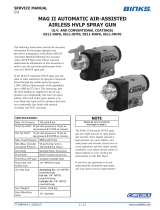
Automatic air spray gun for fine finish application of various paints and coatings. For
professional use only.
300 psi (2.1 MPa, 21 bar) maximum working fluid pressure.
100 psi (0.7 MPa, 7 bar) maximum working air pressure.
Important Safety Instructions
Read all warnings and instructions in this
manual before using the equipment. Be
familiar with the proper control and
usage of the equipment. Save these
instructions.
407194D
EN
Stellair™ Auto Air
Spray Gun

2 407194D
Contents
Models . . . . . . . . . . . . . . . . . . . . . . . . . . . . . . . . . . . . 3
Warnings . . . . . . . . . . . . . . . . . . . . . . . . . . . . . . . . . . 4
Installation. . . . . . . . . . . . . . . . . . . . . . . . . . . . . . . . . 6
Ventilate the Spray Booth . . . . . . . . . . . . . . . . . . 6
Grounding . . . . . . . . . . . . . . . . . . . . . . . . . . . . . . 6
Manifold Setup. . . . . . . . . . . . . . . . . . . . . . . . . . . 7
Mount the Gun and Manifold . . . . . . . . . . . . . . . . 9
Adjust the True Zero Reference Marks View . . . 10
Air Line Installation. . . . . . . . . . . . . . . . . . . . . . . 11
Fluid Line Installation . . . . . . . . . . . . . . . . . . . . . 12
Setup . . . . . . . . . . . . . . . . . . . . . . . . . . . . . . . . . . . . 13
Position the Air Cap . . . . . . . . . . . . . . . . . . . . . . 13
Position the Spray Gun and Workpiece. . . . . . . 14
Adjust Spray Pattern . . . . . . . . . . . . . . . . . . . . . 14
Flush Before Using. . . . . . . . . . . . . . . . . . . . . . . 16
Operation. . . . . . . . . . . . . . . . . . . . . . . . . . . . . . . . . 17
Pressure Relief Procedure . . . . . . . . . . . . . . . . . 17
Spray Finishing Application . . . . . . . . . . . . . . . . 17
Flushing and Cleaning . . . . . . . . . . . . . . . . . . . . . . 18
Flushing Procedure . . . . . . . . . . . . . . . . . . . . . . 18
Daily Cleaning Procedure . . . . . . . . . . . . . . . . . 19
Troubleshooting . . . . . . . . . . . . . . . . . . . . . . . . . . . 20
Fluid Troubleshooting. . . . . . . . . . . . . . . . . . . . . 20
Air Troubleshooting . . . . . . . . . . . . . . . . . . . . . . 21
Spray Pattern Troubleshooting . . . . . . . . . . . . . 22
Repair . . . . . . . . . . . . . . . . . . . . . . . . . . . . . . . . . . . 24
Prepare Equipment for Service . . . . . . . . . . . . . 24
Air Cap Assembly Repair . . . . . . . . . . . . . . . . . . 24
Fluid Cartridge Repair . . . . . . . . . . . . . . . . . . . . 25
Piston Repair . . . . . . . . . . . . . . . . . . . . . . . . . . . 27
Replace Manifold Seals . . . . . . . . . . . . . . . . . . . 28
Fluid Control Knob and Piston Cap Repairs . . . 28
Parts . . . . . . . . . . . . . . . . . . . . . . . . . . . . . . . . . . . . 30
Kits and Accessories . . . . . . . . . . . . . . . . . . . . . . . 32
Fluid Cartridge and Fluid Nozzle Information . . . 36
Air Cap and Air Flow . . . . . . . . . . . . . . . . . . . . . . . 37
Compatible Manifolds . . . . . . . . . . . . . . . . . . . . . . 39
Mounting Hole Layout and Dimensions . . . . . . . . 41
Gun Mounting Kit 24C208 . . . . . . . . . . . . . . . . . 45
Gun Mounting Kit 24B609 . . . . . . . . . . . . . . . . . 45
Retrofit Adapter Plate 288197 . . . . . . . . . . . . . . 45
Single Gun Mounting Bracket 24Y515. . . . . . . . 46
Dual Gun Mounting Bracket 25A844 . . . . . . . . . 46
Robot Adapter Plates. . . . . . . . . . . . . . . . . . . . . 47
Technical Specifications . . . . . . . . . . . . . . . . . . . . 49
Graco Standard Warranty. . . . . . . . . . . . . . . . . . . . 50
Approvals
Spray Technology
Conventional: Optimized for excellent finish quality
and high production rates.
HVLP: High transfer efficiency gun that limits the air
pressure at the air cap to 10 psi (0.07 MPa, 0.7 bar)
maximum.
Compliant: High transfer efficiency gun with a transfer
efficiency greater than or equal to HVLP guns.
Applications
Operate all guns from delivery systems, such as
pressure pots or pumps.
General Industry: Sprays most industrial coatings or
finishes used for industrial, automotive, aerospace,
marine, wood, plastic, and architectural applications.
Air Brush: Delivers a round spray pattern for precise,
small surface area spraying.
Adhesive: Applies waterborne and solventborne
adhesives and sealants.
Trim: Delivers a spray pattern with a well-defined edge
and minimal overspray for selective coating
applications such as edges or trim. Compatible with
most industrial coatings, including dielectric materials.
II 2 G
Ex h IIB T6 Gb

Models
407194D 3
Models
Gun Models with Manifolds
Gun Models
A manifold is required. See Compatible Manifolds, page 39.
Application Included
Manifold
Nozzle Size
in. (mm)
Fluid Control
Knob
Included
Spray Technology
Conventional HVLP Compliant
General Industry with Side
Inlet Manifold (Inch) 25F155 0.055 (1.4)
✓25F213 25F215 25F217
25F212 25F214 25F216
General Industry with Side
Inlet Manifold (Metric) 25F315 0.055 (1.4)
✓25F219 — —
25F218 — —
Application Nozzle Size
in. (mm)
Fluid Control Knob
Included
Spray Technology
Conventional HVLP Compliant
General Industry 0.030 (0.8)
✓25F167 25F174 25F181
25F163 25F170 25F177
General Industry 0.042 (1.1)
✓25F168 25F175 25F182
25F164 25F171 25F178
General Industry 0.055 (1.4)
✓25F169 25F176 25F183
25F165 25F172 25F179
General Industry 0.070 (1.8) 25F166 25F173 25F180
Air Brush 0.042 (1.1) 25F208 — —
Air Brush ✓25F209 — —
Adhesive 0.051 (1.3) 25F210 — —
Adhesive 0.07 (1.8) 25F211 — —
Trim 0.042 (1.1)
✓25F206
Trim 25F204
Trim 0.055 (1.4)
✓25F207
Trim 25F205

Warnings
4 407194D
Warnings
The following warnings are for the setup, use, grounding, maintenance, and repair of this equipment. The
exclamation point symbol alerts you to a general warning and the hazard symbols refer to procedure-specific risks.
When these symbols appear in the body of this manual or on warning labels, refer back to these Warnings.
Product-specific hazard symbols and warnings not covered in this section may appear throughout the body of this
manual where applicable.
WARNING
FIRE AND EXPLOSION HAZARD
Flammable fumes, such as solvent and paint fumes, in work area can ignite or explode. Paint or
solvent flowing through the equipment can cause static sparking. To help prevent fire and explosion:
• Use equipment only in well-ventilated area.
• Eliminate all ignition sources; such as pilot lights, cigarettes, portable electric lamps, and plastic
drop cloths (potential static sparking).
• Ground all equipment in the work area. See Grounding, instructions.
• Never spray or flush solvent at high pressure.
• Keep work area free of debris, including solvent, rags and gasoline.
• Do not plug or unplug power cords, or turn power or light switches on or off when flammable fumes
are present.
• Use only grounded hoses.
• Hold gun firmly to side of grounded pail when triggering into pail. Do not use pail liners unless they
are anti-static or conductive.
•Stop operation immediately if static sparking occurs or you feel a shock. Do not use equipment
until you identify and correct the problem.
• Keep a working fire extinguisher in the work area.
PRESSURIZED EQUIPMENT HAZARD
Fluid from the equipment, leaks, or ruptured components can splash in the eyes or on skin and cause
serious injury.
• Follow the Pressure Relief Procedure when you stop spraying/dispensing and before cleaning,
checking, or servicing equipment.
• Tighten all fluid connections before operating the equipment.
• Check hoses, tubes, and couplings daily. Replace worn or damaged parts immediately.
TOXIC FLUID OR FUMES HAZARD
Toxic fluids or fumes can cause serious injury or death if splashed in the eyes or on skin, inhaled, or
swallowed.
• Read Safety Data Sheets (SDSs) to know the specific hazards of the fluids you are using.
• Store hazardous fluid in approved containers, and dispose of it according to applicable guidelines.

Warnings
407194D 5
EQUIPMENT MISUSE HAZARD
Misuse can cause death or serious injury.
• Do not operate the unit when fatigued or under the influence of drugs or alcohol.
• Do not exceed the maximum working pressure or temperature rating of the lowest rated system
component. See Technical Specifications in all equipment manuals.
• Use fluids and solvents that are compatible with equipment wetted parts. See Technical
Specifications in all equipment manuals. Read fluid and solvent manufacturer’s warnings. For
complete information about your material, request Safety Data Sheets (SDSs) from distributor or
retailer.
• Turn off all equipment and follow the Pressure Relief Procedure, when equipment is not in use.
• Check equipment daily. Repair or replace worn or damaged parts immediately with genuine
manufacturer’s replacement parts only.
• Do not alter or modify equipment. Alterations or modifications may void agency approvals and
create safety hazards.
• Make sure all equipment is rated and approved for the environment in which you are using it.
• Use equipment only for its intended purpose. Call your distributor for information.
• Route hoses and cables away from traffic areas, sharp edges, moving parts, and hot surfaces.
• Do not kink or over bend hoses or use hoses to pull equipment.
• Keep children and animals away from work area.
• Comply with all applicable safety regulations.
PERSONAL PROTECTIVE EQUIPMENT
Wear appropriate protective equipment when in the work area to help prevent serious injury, including
eye injury, hearing loss, inhalation of toxic fumes, and burns. Protective equipment includes but is not
limited to:
• Protective eyewear, and hearing protection.
• Respirators, protective clothing, and gloves as recommended by the fluid and solvent
manufacturer.
WARNING

Installation
6 407194D
Installation
Ventilate the Spray Booth
The spray booth must have a ventilation system.
Electrically interlock the gun fluid supply with the
ventilators to prevent gun operation any time that the
ventilation air flow falls below minimum values. Check
and follow all local codes and regulations regarding air
exhaust velocity requirements. Verify the operation of
the interlock at least once a year.
Grounding
The following grounding instructions are minimum
requirements for a system. Your system may include
other equipment or objects that must be grounded.
Check your local electrical code for detailed grounding
instructions for your area and type of equipment. Your
system must be connected to a true earth ground.
Spray Gun: Ground the spray gun by mounting it to a
grounded mount, such as a reciprocator, robot, or
stationary support, and connect the gun to a properly
grounded fluid hose and pump.
Pump: Ground the pump by connecting a ground wire
and clamp between the pump and a true earth ground
as instructed in your separate pump instruction manual.
Air Compressors and Hydraulic Power Supplies:
Ground air compressors and hydraulic power supplies
according to the manufacturer recommendations.
Air, Fluid, and Hydraulic Hoses Connected To Pump:
Use only electrically conductive hoses with a maximum
of 100 ft (30.5 m) combined hose length to ensure
grounding continuity. Check the electrical resistance of
your air and fluid hoses at least once a week. If the total
resistance to ground exceeds 25 megohms, replace the
hose immediately. Use a meter that is capable of
measuring resistance at this level.
Fluid Supply Container: Ground the fluid supply
container according to local code and regulations.
Object Being Sprayed: Ground the object that is being
sprayed according to local code and regulations.
Solvent Pails: Ground all solvent pails used during the
Flushing Procedure according to local code. Use only
metal pails, which are conductive. Do not place the pail
on a non-conductive surface, such as paper or
cardboard, which interrupts the grounding continuity.
Do not operate the gun unless ventilating air flow is
above the minimum required value. Provide fresh air
ventilation to avoid the buildup of flammable or toxic
vapors when spraying, flushing, or cleaning the gun.
Interlock the gun fluid supply to prevent operation
unless ventilating air flow is above the minimum
required value.
The equipment must be grounded to reduce the risk
of static sparking. Static sparking can cause fumes
to ignite or explode. Grounding provides an escape
wire for the electric current.

Installation
407194D 7
Manifold Setup
Manifold connection locations vary by manifold. See
Compatible Manifolds, page 39 for manifold part
details.
Install Air Fittings on the Manifold
Manifold connection locations vary by manifold. See
Compatible Manifolds, page 39 for manifold part
details.
1. Install a tube fitting (104) into the cylinder air inlet
(CYL).
2. Install a tube fitting (105) into the fan air inlet (FAN)
and the atomizing air inlet (ATOM).
Install Fluid Connectors and Gun on the
Manifold
Circulating System Configuration
1. Apply anti-seize lubricant 222955 to the mating
faces of the manifold and the fluid connector
threads (102).
2. Install the fluid connector fitting (102) in the fluid
ports (FLP). See FIG. 1.
3. Connect the fluid supply hose to one fluid
connector fitting (102) and the fluid return hose to
the other connector (102). See Gun Fluid Line
Installation, page 12.
4. Remove the internal fluid plug (17). See FIG. 4.
5. Install the two fluid o-rings (108) supplied with the
manifold.
NOTE: The fluid ports (FLP) are reversible.
6. Lubricate the manifold o-rings (107 and 108) with
the recommended Light-Weight Oil, page 35.
FIG. 1: Air Fittings and Fluid Supply Inlets
104
105 FIG. 2: Fluid Port Connections (Circulating
Configuration)
102
102
2
2
2
FLP
Apply anti-seize lubricant

Installation
8 407194D
7. Secure the gun to the manifold with the mounting
screws (4). Torque to 65 in-lb (7.3 N•m)
Non-Circulating System Configuration
1. Apply anti-seize lubricant 222955 to the fluid port
(FLP) threads, fluid connector thread (102), and the
pipe plug (103).
2. Install a fluid connector fitting (102) in one fluid port,
and a pipe plug (103) in the other port.
3. Connect the fluid supply hose to the fluid connector
fitting (102). See Gun Fluid Line Installation on
page 12.
4. Lubricate and install the internal fluid plug (17) with
o-ring (17a) in the gun fluid port on the same side
as the pipe plug (103). Use the recommended
Light-Weight Oil, page 35.
5. Install one fluid o-ring (108) in the manifold fluid
port opposite the internal fluid plug.
NOTE: Make sure to remove the fluid o-ring (108)
before installing the internal fluid plug (17).
FIG. 3: Mounting Screw Location
4
4
Torque to 65 in-lb
(7.3 N•m)
3
4
4
Lubricate with a
lightweight oil
107
108
3
FIG. 4: Fluid Port Connections (Non-Circulating
Systems
Lubricate with recommended
Light-Weight Oil
103
102
2
17
4
4
2Apply anti-seize lubricant
(Remove in a
circulating
system)
FLP
2
17a
4
107
4
108
2

Installation
407194D 9
Mount the Gun and Manifold
Reciprocating Arm Rod Mount Installation
The gun fits a 0.5 in. (13 mm) diameter maximum
reciprocating arm rod.
1. Insert a mounting bar (MB) through the hole in the
manifold.
2. Tighten the set screw (106) to secure the gun to the
manifold.
NOTE: The manifold notches (MN) fit 1/8 in. alignment
pins. Use as desired.
Stationary Support Installation
Mount the gun on a stationary support or robot
mounting bracket. Refer to the Mounting Hole Layout
and Dimensions, page 41 for the manifold
measurements and screw hole depth.
1. Tighten or remove the setscrew (106) with a hex
key.
2. Locate alignment pins and holes per the Mounting
Hole Layout and Dimensions illustration, page 41.
3. Align the manifold with alignment pins (AP).
4. Secure the gun to the support with capscrews (CS).
FIG. 5: Reciprocating Arm Mount
MB
106
MN
FIG. 6: Stationary Support Mount
CS
106
AP

Installation
10 407194D
Adjust the True Zero Reference
Marks View
Optional Setup: Gun models with a fluid control knob
(8) have a true zero set point. See True Zero
Reference Checklist, page 28.
If desired, rotate the fluid control knob assembly so the
operator can see the reference marks (M1 and M2). Use
a hex key to adjust set screws.
1. Turn the fluid control knob (8) counter-clockwise
until it stops.
2. Slightly loosen the piston cap set screw (5a).
3. Rotate the fluid control knob assembly so the true
zero marking (M2) is visible.
4. Tighten the piston cap set screw (5a).
5. Reset Gun to True Zero, page 29.
NOTICE
Use caution when closing the fluid control knob.
The needle tip may be damaged if forced too hard
against the nozzle seat by the fluid control knob.
FIG. 7: Piston Set Screw Location
5a
8
5
M1
M2

Installation
407194D 11
Air Line Installation
Main Air Line Typical Installation
•Bleed-type master air valve: required in your
system to relieve air trapped between the pump
and the gun when the valve is closed.
NOTE: Be sure the valve is easily accessible from the
pump and located downstream from the air regulator.
•Pump air pressure regulator: to control pump
speed and fluid outlet pressure. Locate it close to
the pump.
•Air line filter: removes harmful dirt and moisture
from compressed air supply. Ensures a dry, clean
air supply.
•Air shutoff valve: shuts off air to the gun and
pump.
Gun Air Hose Installation
Connect air hoses to the gun cylinder (CYL), fan (FAN),
and atomizing (ATOM) air connectors.
Manifolds with three air inlets: Supply and regulate
each air line separately.
Manifolds with a fan adjustment valve: Supply and
regulate the fan and atomizing air with one air
connection.
1. Connect an air hose (D) to each air fitting. Use 3/8
in. (9.5 mm) O.D. tubing for fan and atomizing air to
minimize excessive pressure drop in the hoses.
2. Install an air pressure regulator (F) on each gun air
hose.
NOTE: The fan and atomizing air regulators must have
a minimum air flow capacity of 30 scfm at 100 psi (0.7
MPa, 7.0 bar) air pressure.
3. Install a bleed-type air shutoff valve (E) on each gun
air hose. Install downstream of the gun air regulator
to shut off air to the gun.
4. Connect each gun air hose (D) to the main air
supply line.
Trapped air can cause the gun to spray
unexpectedly, which could result in serious injury
from splashing fluid. To help prevent injury, install a
bleed-type master air valve.
FIG. 8: Cylinder, Fan, and Atomizing Connections
FIG. 9: Gun Air Hose Connections
FIG. 10: Gun Air Hose Typical Installation
D
F
E

Installation
12 407194D
Fluid Line Installation
Main Fluid Line Installation
•Fluid filter: with a 60 or 100 mesh (250 micron)
stainless steel element to filter particles from the
fluid as it leaves the pump. Always use a clean fluid
filter.
•Fluid drain valve: relieves fluid pressure in the
hose and gun. Required in your system to assist in
relieving fluid pressure in the displacement pump,
hose and gun; triggering the gun to relieve pressure
may not be sufficient.
•Fluid shutoff valve: shuts off fluid flow. Can be
installed in the fluid line to the gun.
•Fluid pressure regulator: for more precise
adjustment of the fluid pressure. Install a fluid
pressure regulator on the main fluid line if the
pump’s maximum working pressure exceeds the
gun's maximum fluid working pressure. See
Technical Specifications, page 49.
Gun Fluid Line Installation
Before connecting the fluid hose, blow it out with air
and flush it with solvent. Use solvent that is compatible
with the fluid to be sprayed.
1. Install a fluid pressure regulator (L) on the gun fluid
hose.
NOTE: Some applications require fine-tuned control of
fluid pressure. You can control fluid pressure more
accurately with a fluid pressure regulator than by
regulating the air pressure to the pump.
2. Install a fluid shutoff valve (M) on the gun fluid line
to shut off the fluid supply to the gun.
3. Connect the gun fluid supply hose (J) to a gun fluid
connector fitting (102). In a circulating system,
connect the fluid return hose to the other fluid
connector (102).
FIG. 11: Gun Fluid Line Typical Installation
FIG. 12: Fluid Supply and Fluid Return Connections
ti7016a
L
M
J
J
102

Setup
407194D 13
Setup
Position the Air Cap
NOTE: Air Brush air caps do not include alignment
pints.
Vertical Spray Pattern
Air caps are factory-set with the alignment pin set to a
vertical spray pattern.
Horizontal Spray Pattern
To change the air cap to a horizontal spray pattern, use
a hex key to unscrew the alignment pin and relocate it
to the horizontal spray pattern hole. When relocating
the pin use low strength thread locker. Torque to
1.5–2.5 in-lb (0.2–0.3 N•m). Do not overtighten.
Angled Spray Pattern
Use the gauge on the Alignment Tool: 2000481 to
quickly set precise spray pattern angles. The alignment
tool is sold separately. See Alignment Tool: 2000481,
page 34.
1. Tighten the assembled air cap onto the gun body.
2. Place the alignment tool onto the gun.
3. Rotate the alignment tool to the desired angled
spray pattern position.
4. Remove the tool before spraying.
FIG. 13: Vertical Spray Pattern (Factory-Set Position)
FIG. 14: Air Cap Alignment Pin Positions
FIG. 15: Horizontal Spray Pattern
Horizontal
Vertical
FIG. 16: Alignment Tool on an Air Cap in the Vertical
Position (0°)
FIG. 17: 160° Angled Spray Pattern

Setup
14 407194D
Position the Spray Gun and
Workpiece
The 8 in. (300 mm) path guides on the Alignment Tool:
2000481 help visualize the spray center point and the
distance between the gun and the workpiece. The
alignment tool is sold separately. See Alignment Tool:
2000481, page 34.
Adjust Spray Pattern
Set Fluid Flow
1. Adjust the Fluid Pressure Regulator (L) to set the
fluid flow rate. Typical industrial flow rates will vary
with regulator pressures from 5–30 psi (34–210
kPa, 0.3–2.1 bar).
2. Supply a minimum of 50 psi (0.34 MPa, 3.4 bar) air
pressure to the cylinder (CYL) air line to trigger the
gun.
3. Make fluid flow adjustments.
•Fluid Regulator (L): Increase or decrease the fluid
pressure to achieve desired flow rate.
•Fluid Control Knob (8) (select models): make fine
adjustments to the flow with the fluid control knob.
-Open: Turn counter-clockwise to increase the
fluid flow.
-Close: Turn clockwise to decrease.
•Adjust nozzle size: Check fluid pressure and
change nozzle if needed. See Fluid Cartridge and
Fluid Nozzle Information, page 36.
- If the fluid pressure is too high at the desired
flow rate, install a larger nozzle.
- If the fluid pressure is too low at the desired
flow rate, install a smaller nozzle.
NOTE: A larger fluid nozzle at a reduced fluid pressure
will maintain the same flow rate, but the fluid stream
(velocity) will slow down. When air is applied, the lower
velocity allows the air to act on the fluid longer, which
improves atomization.
Supply Fan and Atomizing Air
Use the air pressure regulator (F) to set the fan and
atomizing air pressure. Use the Recommended
Starting Pressures as a starting point. Note Maximum
Fan and Atomizing Manifold Inlet Pressure
Requirements, page 15.
FIG. 18: Alignment Tool Path Guides
NOTICE
Use caution when operating the fluid control knob
near the closed position. The needle tip may be
damaged if forced too hard against the nozzle seat
by the fluid control knob.
FIG. 19: Fluid Control Knob Adjustments
FIG. 20: Fluid Flow Coverage
Increase Decrease

Setup
407194D 15
Recommended Starting Pressures
* Pattern created from a 10 in. spray distance, using a
0.055 in. (1.4 mm) nozzle orifice.
Maximum Fan and Atomizing Manifold Inlet
Pressure Requirements
Test Fan and Atomizing Air
Test the spray pattern while keeping the gun a
consistent distance, about 6–8 in. (150–200 mm), from
the test piece. Adjust atomizing and fan air as needed.
Adjust Atomizing Air
For the best transfer efficiency, use the lowest setting
needed to achieve desired finish quality.
Increase the gun atomizing air supply pressure with the
air pressure regulator in 5 psi (34 kPa, 0.3 bar)
increments until you obtain the desired atomization.
Note Maximum Fan and Atomizing Manifold Inlet
Pressure Requirements for HVLP and compliant guns.
Adjust Fan Air
If the spray pattern is too wide or split, reduce the fan
air pressure (or slightly close the fan adjustment valve
on the manifold if using manifold 2000226). Note
Maximum Fan and Atomizing Manifold Inlet
Pressure Requirements for HVLP and compliant guns.
Application and
Technology
Fan Air
psi (MPa, bar)
Atomizing Air
psi (MPa, bar)
*Fan Pattern
Width 100ccm,
20cps
*Fan Pattern
Width 100ccm,
100cps
General Industry:
Conventional
25 (0.17, 1.7) 25 (0.17, 1.7) 12 8
General Industry:
HVLP
25 (0.17, 1.7) 25 (0.17, 1.7) 12 9
General Industry:
Compliant
25 (0.17, 1.7) 25 (0.17, 1.7) 13.5 13
Trim: HVLP 10 (0.07, 0.7) 10 (0.07, 0.7) 9.5 8
Adhesive 20 (0.14, 1.4) 20 (0.14, 1.4) 5 5
Air Brush 20 (0.14, 1.4) 20 (0.14, 1.4) N/A N/A
Application and
Technology
Maximum
Fan Air
Pressure
psi (MPa, bar)
Maximum
Atomizing Air
Pressure
psi (MPa, bar)
General
Industry: HVLP
29 (0.20, 2.0) 17 (0.12, 1.2)
General
Industry:
Compliant
33 (0.23, 2.3) 29 (0.20, 2.0)
Trim: HVLP 14 (0.0965,
965)
12 (0.08, 0.8)
FIG. 21: Atomizing Air
FIG. 22: Fan Air
Increase Decrease

Setup
16 407194D
To further control the spray pattern, use an alternate air
cap. See Air Cap and Air Flow, page 37.
HVLP and Compliant Gun Limits
In some areas, an HVLP gun is required for compliance
with environmental standards. To comply with HVLP
requirements, the air pressure at the air cap must be
less than 10 psi (0.07 MPa, 0.7 bar).
See Air Cap and Air Flow, page 37 for maximum HVLP
and Compliant manifold inlet pressures. To verify the
pressure at the air cap, use an appropriate HVLP
Pressure Verification Kit, page 35.
Flush Before Using
The equipment was tested with lightweight oil, which is
left in the fluid passages to protect parts. To avoid
contaminating your fluid with oil, flush the equipment
with a compatible solvent before using the equipment.
See Flushing Procedure, page 18.
FIG. 23: Fan Air
Increase Decrease

Operation
407194D 17
Operation
Pressure Relief Procedure
Follow the Pressure Relief Procedure whenever
you see this symbol.
1. Turn off the fluid supply to the gun.
2. Turn off the fan and atomizing air supply to the gun.
3. Trigger the gun into a grounded metal waste
container to relieve the pressure.
4. Turn off the cylinder air supply to the gun.
5. Close the bleed-type master air valve (required in
the system).
6. Open the fluid drain valve (required in the system)
to relieve fluid pressure in the gun and hose. In
addition, relieve fluid pressure in the fluid supply
equipment as instructed in its instruction manual.
Have a container ready to catch the drainage.
Leave all drain valves open until you are ready to
spray again.
7. If you suspect that the nozzle or hose is completely
clogged or that pressure has not been fully relieved:
a. Very slowly loosen the fluid hose end coupling
to relieve pressure gradually.
b. Loosen the coupling completely.
c. Clear the obstruction in the hose or nozzle.
Spray Finishing Application
When triggered, the gun begins emitting air before the
fluid discharges. When the cylinder air stops, the fluid
stops before the airflow stops. This lead and lag
operation helps ensure proper spray atomization and
prevents fluid buildup on the air cap.
1. Adjust Spray Pattern. See page 14.
2. Position the workpiece. Adjust the system control
device, if it is automatic, so the gun starts spraying
just before meeting the workpiece and stops as
soon as it passes.
3. Keep the gun perpendicular and 6–8 in. (150–200
mm) from the workpiece.
4. Supply a minimum of 50 psi (0.34 MPa, 3.4 bar) air
pressure to the cylinder (CYL) air line to trigger the
gun.
5. Use smooth, parallel strokes across the workpiece
surface with 50 percent overlap.
6. Flush the equipment. See Flushing and Cleaning,
page 18.
This equipment stays pressurized until pressure is
manually relieved. To help prevent serious injury from
pressurized fluid, such as splashing fluid, follow the
Pressure Relief Procedure when you stop spraying
and before cleaning, checking, or servicing the
equipment.
FIG. 24: Correct Spray Method
Incorrect
Correct

Flushing and Cleaning
18 407194D
Flushing and Cleaning
• Follow the Daily Cleaning Procedure every day.
• Flush before changing colors, before fluid can dry
in the equipment, at the end of the day, before
storing, and before repairing equipment.
• Flush at the lowest pressure possible. Check
connections for leaks and tighten as necessary.
• Flush with a fluid that is compatible with the fluid
being dispensed and the equipment wetted parts.
• Clean the front of the air cap regularly to reduce
buildup.
• Do not use any cleaning method which may allow
solvent into the gun air passages. Solvent left in
gun air passages could result in a poor quality paint
finish.
- Do not point gun up while cleaning.
- Do not wipe the gun with a cloth soaked in
solvent; wring out the excess.
- Do not immerse the gun in solvent.
Flushing Procedure
1. Follow the Pressure Relief Procedure, page 17.
2. Connect a solvent supply hose to the gun.
3. To maintain grounding continuity hold metal part of
the spray gun firmly to the side of a grounded metal
solvent pail.
4. Turn on the gun cylinder (CYL) air.
5. Starting with the lowest possible fluid pressure,
trigger the gun into a grounded metal solvent pail.
6. Increase the fluid pressure slowly. Flush until clean
solvent flows from the gun.
7. De-trigger the gun.
8. Turn off the solvent supply.
9. Follow the Pressure Relief Procedure, page 17.
To reduce the risk of an injury from splashing fluid,
follow the Pressure Relief Procedure, page 17,
whenever you are instructed to relieve the pressure.
To avoid fire and explosion, always ground equipment
and waste container. To avoid static sparking and
injury from splashing fluid, always flush at the lowest
possible pressure.
NOTICE
Methylene chloride with formic or propionic acid is
not recommended as a flushing or cleaning solvent
with this gun as it will damage aluminum and nylon
components. FIG. 25: Flushing into a Grounded Metal Container

Flushing and Cleaning
407194D 19
Daily Cleaning Procedure
1. Follow the Pressure Relief Procedure, page 17.
2. Flush the equipment. See Flushing Procedure,
page 18.
3. Remove the air cap assembly. See Remove the Air
Cap Assembly, page 24.
4. Dip the end of a soft-bristle brush into a compatible
solvent. Do not continuously soak the brush’s
bristles.
5. Clean the components. Replace seals as needed.
a. Clean the parts with a soft-bristle brush.
b. Use a soft tool, such as an unclogging needle
or tooth pick, to clean the air cap (6) holes.
6. Dampen a soft cloth with solvent and wring-out the
excess. Point the gun down and wipe off the
outside of the gun.
7. Assemble and install the air cap assembly. See
Install the Air Cap Assembly, page 24.
NOTICE
Do not use metal tools to clean the air cap assembly
parts. Metal tools may scratch the air cap and cause
spray pattern distortion.
FIG. 26: Clean Air Cap Components
7b 6
7a
7

Troubleshooting
20 407194D
Troubleshooting
1. Follow the Pressure Relief Procedure, page 17
before checking or repairing the gun.
2. Check all possible problems and causes before
disassembling gun.
Fluid Troubleshooting
Problem Cause Solution Reference
Fluid leakage
through venting
holes
Worn fluid cartridge seals Replace the fluid cartridge or the
seals
Fluid Cartridge Repair,
page 25
Worn, dirty, or damaged
fluid needle
Replace the fluid cartridge or the
fluid needle
Loose packing nut Replace the fluid cartridge or tighten
packing nut
Fluid leakage
from front of gun
Fluid needle tip is dirty,
worn, or damaged
Replace the fluid cartridge Fluid Cartridge Repair,
page 25
Clean or replace fluid needle tip or
entire needle
FIG. 30: Needle Assembly,
page 25
Dirty or worn nozzle Replace the fluid cartridge Fluid Cartridge Repair,
page 25
Clean or replace nozzle FIG. 31: Nozzle and Fluid
Insert, page 25
Fluid is present
at air cap holes
Nozzle is insufficiently
tightened
Tighten the fluid cartridge Install the Fluid Cartridge,
page 25
Tighten the nozzle FIG. 31: Nozzle and Fluid
Insert, page 25
Fluid does not
flow
Fluid needle will
not trigger
Insufficient cylinder (CYL)
air pressure supplied to
the gun on trigger
Increase cylinder (CYL) air pressure
or clean the air line
Air Line Installation,
page 11
Missing ball bearing from
the piston
Replace the ball bearings Check Piston Ball
Bearings, page 27
Air leaking around piston Replace piston o-ring or piston Replace Piston Seals,
page 27
Swollen piston o-ring Replace piston o-ring. Piston Repair, page 27
Internal fluid plug is
incorrectly installed
Non-Circulating System: Move
plug to fluid port consistent with
manifold plumbing
FIG. 4: Fluid Port
Connections
(Non-Circulating Systems,
page 8
Circulating System: All fluid ports
in gun and on manifold should be
open
FIG. 2: Fluid Port
Connections (Circulating
Configuration), page 7
/