Page is loading ...

77-2774-R6 (4/2019) 1 / 4 www.carlisleft.com
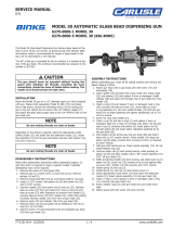
The Model 30 High Flow Glass Bead
Dispensing Gun delivers glass beads
at the rate of up to 60 lbs./min. (A
pressure tank with follower plate and
bottom outlet is recommended for
supply of glass beads to the gun.) Air
for atomization is not required.
“On-off” of the gun is provided by the
air cylinder. It is located at the rear of
the gun body. The minimum recom-
mended air pressure to the cylinder is
50 PSIG.
INSTALLATION
Mount the Model 30 gun on a 1/2" diameter steel rod. (Not fur-
nished with gun. Please order separately, Model 54-380.) The
rod should have a flat area to receive the mounting screw (16)
for locking the gun to the rod. Attach the air hose to the 1/4"
NPS(m) nipple (18) and attach the glass bead supply hose to the
3/4" NPS(m) inlet on the gun head (13).
DISASSEMBLY INSTRUCTIONS
Read entire disassembly instructions before attempting repairs.
Do only that which is required to repair a specific trouble.
Complete disassembly may not be required.
1. Remove screw (24) and guard (25).
2. Remove cap (3), control screw (1) and lock-nut (2).
Remove springs (4) and (5).
3. Remove deflection nozzle (29) and nozzle insert (28) by
unscrewing retainer ring (10).
4. Using a 11/16" socket, hold piston rod (6) and loosen nut
(19) with a 7/16" wrench.
5. Unscrew needle (12) from piston rod (6) and nut (19).
Remove take-up screw (20) from gun head (13). Since
o-ring (21) and take-up screw (20) offer resistance to
removal from needle (12), unscrew take-up screw (20) from
needle (12), rather than pulling forcefully. Remove needle
(12) from front of gun head (13).
6. Remove wiper (22) and retainer (23) from gun head (13).
7. Remove piston rod (6) and piston (8) by feeding air into the
air inlet (18) at 5-10 PSIG.
8. Remove screw (14) and lockwasher (15) and separate gun
body (17) from gun head (13).
ASSEMBLY INSTRUCTIONS
Before assembling gun, clean off all mating surfaces and
remove any beads clinging to them.
1. Attach gun head (13) to gun body (17) with screw (14) and
lockwasher (15).
2. Insert needle (12) through front of gun head (13). Check
wiper (22) and retainer (23) and replace if worn or dam-
aged. Install retainer (23) and wiper (22) through rear of
gun head (13) onto needle (12).
3. Check o-ring (21) and replace if worn or damaged. Seat
o-ring (21) correctly into take-up screw (20). Screw take-up
screw o-ring assembly (20, 21) over needle threads (12)
and into gun head (13) to finger tightness and tighten addi-
tionally 1/8 to 1/4 turn by wrench.
4. Screw nut (19) onto needle (12).
5. Check u-cup (9) and two o-rings (7) and replace if worn or
damaged. Seat two o-rings (7) correctly onto piston rod (6)
and seat u-cup (9) correctly onto piston (8). Insert piston
rod (6) through piston (8) and insert piston rod/piston
assembly (6, 8) into gun body (17).
6. Push piston rod (6) all the way into gun body (17) and hold
it there with 11/16" socket wrench. Screw needle (12) deep
into piston rod (6) while, at same time, turning nut (19), as
required, to avoid “lockup”.
7. Hold gun with nozzle end up. Insert nozzle insert (28) and
deflection nozzle (29). Do not install retainer ring (10).
8.
Unscrew piston rod (6) with socket wrench, while pushing
on piston rod (6) and allow needle (12) to “lift” nozzle insert
(29) and deflection nozzle (29) 3/32" off gun head (16).
9. While preventing needle (12) from turning, and while push-
ing on piston rod (6), screw nut (19) forward so as to lock
against take-up screw (20). Tighten nut (19) securely with
7/16" wrench.
10. Install spring (4) and cap (3).
11. Install spring (5), lock-nut (2) and control screw (1).
12. Insert nozzle insert (28) and deflection nozzle (29) into gun
head (13).
13. Check o-ring (11) and replace if worn or damaged. Seat
o-ring (11) correctly onto gun head (13).
14. Screw retainer ring (10) onto gun head (13) and make hand
tight.
15. Attach guard (25) with screw (24) and nut (26).
NOTE
Be sure mating threads are clean of beads.
CAUTION
The gun should never be operated without having the
guard (25) installed. All threads, including the hose con-
nections, should be clean of beads before mating. The
needle (12) should always be kept clean. Failure
to follow these precautions may result in damage to
components.
!
25
MODEL 30 AUTOMATIC HIGH FLOW
GLASS BEAD DISPENSING GUN
6277-3522-5 and 6277-3525-7
EN
SERVICE MANUAL

EN
77-2774-R6 (4/2019)2 / 4www.carlisleft.com
LOCK OUT / TAG-OUT
Failure to de-energize, disconnect, lock out and tag-out all power
sources before performing equipment maintenance could cause
serious injury or death.
OPERATOR TRAINING
All personnel must be trained before operating finishing
equipment.
EQUIPMENT MISUSE HAZARD
Equipment misuse can cause the equipment to rupture,
malfunction, or start unexpectedly and result in serious injury.
PROJECTILE HAZARD
You may be injured by venting liquids or gases that are released
under pressure, or flying debris.
PINCH POINT HAZARD
Moving parts can crush and cut. Pinch points are basically any
areas where there are moving parts.
INSPECT THE EQUIPMENT DAILY
Inspect the equipment for worn or broken parts on a daily basis.
Do not operate the equipment if you are uncertain about its
condition.
In this part sheet, the words WARNING, CAUTION and NOTE are used to
emphasize important safety information as follows:
Hazards or unsafe practices which
could result in minor personal injury,
product or property damage.
!
CAUTION
Hazards or unsafe practices which
could result in severe personal
injury, death or substantial property
damage.
!
WARNING
Important installation, operation or
maintenance information.
NOTE
Read the following warnings before using this equipment.
READ THE MANUAL
Before operating finishing equipment, read and understand all
safety, operation and maintenance information provided in the
operation manual.
WEAR SAFETY GLASSES
Failure to wear safety glasses with side shields could result in
serious eye injury or blindness.
NEVER MODIFY THE EQUIPMENT
Do not modify the equipment unless the manufacturer provides
written approval.
IT IS THE RESPONSIBILITY OF THE EMPLOYER TO PROVIDE THIS INFORMATION TO THE OPERATOR OF THE EQUIPMENT.
FOR FURTHER SAFETY INFORMATION REGARDING THIS EQUIPMENT, SEE THE GENERAL EQUIPMENT SAFETY BOOKLET (77-5300).
KNOW WHERE AND HOW TO SHUT OFF THE EQUIPMENT
IN CASE OF AN EMERGENCY
PRESSURE RELIEF PROCEDURE
Always follow the pressure relief procedure in the equipment
instruction manual.
NOISE HAZARD
You may be injured by loud noise. Hearing protection may be
required when using this equipment.
STATIC CHARGE
Fluid may develop a static charge that must be dissipated through
proper grounding of the equipment, objects to be sprayed and all
other electrically conductive objects in the dispensing area. Improper
grounding or sparks can cause a hazardous condition and result in
fire, explosion or electric shock and other serious injury.
WEAR RESPIRATOR
Toxic fumes can cause serious injury or death if inhaled.
Wear a respirator as recommended by the fluid and solvent
manufacturer’s Material Safety Data Sheet.
TOXIC FLUID & FUMES
Hazardous fluid or toxic fumes can cause serious injury or death if
splashed in the eyes or on the skin, inhaled, injected or
swallowed. LEARN and KNOW the specific hazards or the fluids
you are using.
KEEP EQUIPMENT GUARDS IN PLACE
Do not operate the equipment if the safety devices have been
removed.
!
WARNING
AUTOMATIC EQUIPMENT
Automatic equipment may start suddenly without warning.
FIRE AND EXPLOSION HAZARD
Improper equipment grounding, poor ventilation, open flame or
sparks can cause a hazardous condition and result in fire or
explosion and serious injury.
MEDICAL ALERT
Any injury caused by high pressure liquid can be serious. If you
are injured or even suspect an injury:
• Go to an emergency room immediately.
• Tell the doctor you suspect an injection injury.
• Show the doctor this medical information or the medical alert
card provided with your airless spray equipment.
• Tell the doctor what kind of fluid you were spraying or
dispensing.
GET IMMEDIATE MEDICAL ATTENTION
To prevent contact with the fluid, please note the following:
• Never point the gun/valve at anyone or any part of the body.
• Never put hand or fingers over the spray tip.
• Never attempt to stop or deflect fluid leaks with your hand,
body, glove or rag.
• Always have the tip guard on the spray gun before spraying.
• Always ensure that the gun trigger safety operates before
spraying.

EN
77-2774-R6 (4/2019) 3 / 4 www.carlisleft.com
BINKS MODEL 30 AUTOMATIC HIGH-FLOW GLASS BEAD DISPENSING GUN
16 54-335 MOUNTING SCREW .................... 1
17 54-1194 GUN BODY .................................. 1
18 57-13 D.M. NIPPLE 1/4" NPS x 1/4" NPT ......... 1
19 20-301-1 HEX NUT 1/4"-20 ........................... 1
20 54-1198 SCREW ......................................... 1
21 20-3620•▲ O-RING ........................................ 1
22 54-3114*•▲ WIPER .......................................... 1
23 54-3113*•▲ RETAINER .................................... 1
24 20-4827 SCREW, ROUND HEAD
6-32 x 1 1/4" Long .......................... 1
25 54-1199 GUARD ........................................ 1
26 20-412-1 NUT 6-32 ....................................... 1
27 20-2287-1 PIPE PLUG 1/8" NPT SOC Head ......... 1
28 45-147•■ NOZZLE INSERT 1/2" Dia. .............. 1
29 45-148•■ DEFLECTION NOZZLE 1/2" Dia. ..... 1
PARTS LIST
When ordering, please specify Part No.
ITEM PART
NO. NO. DESCRIPTION QTY.
ITEM PART
NO. NO. DESCRIPTION QTY.
1 54-1195 CONTROL SCREW ......................... 1
2 54-323 CONTROL SCREW LOCKNUT .......... 1
3 54-1196 CAP ............................................... 1
4 54-236 SPRING .......................................... 1
5 54-1648▲ SPRING .......................................... 1
6 54-1197 PISTON ROD ................................. 1
7 20-2369▲ O-RING ......................................... 2
8 102-2059 PISTON .......................................... 1
9 20-3723▲ U-CUP ........................................... 1
10 52-1635 RETAINER RING ............................ 1
11 20-3829▲ O-RING ......................................... 1
12 47-700• NEEDLE ......................................... 1
13 54-1208 GUN HEAD ................................... 1
14 20-702-1 SCREW, HEX HEAD ......................
1/4"-20 x 7/8" Long .......................... 1
15 20-1041-1 LOCKWASHER .............................. 1
* Also available in 54-3116 Wiper Kit. Please order separately.
■ For Standard Nozzle set-ups, see Part Sheet 2151 or order
optional 45-101 Assembly.
▲ Also available in 6-271 Repair Kit. Please order separately.
• Also available in 6-1287 Big Bore Kit. Please order separately.
1
2
3
4
5
6
7
8
9
10 11
29
28
12
13
27
23 22
21
19
18
17
24 25
26
20
14
15 16
NOTE
O-ring (21) fits in groove inside item (20).

EN
77-2774-R6 (4/2019)4 / 4www.carlisleft.com
WARRANTY POLICY
This product is covered by Carlisle Fluid Technologies’ materials and workmanship limited warranty.
The use of any parts or accessories, from a source other than Carlisle Fluid Technologies,
will void all warranties. Failure to reasonably follow any maintenance guidance provided
may invalidate any warranty.
For specic warranty information please contact Carlisle Fluid Technologies.
For technical assistance or to locate an authorized distributor,
contact one of our international sales and customer support locations.
Region Industrial/Automotive Automotive Renishing
Americas Tel: 1-800-992-4657 Tel: 1-800-445-3988
Fax: 1-888-246-5732 Fax: 1-800-445-6643
Europe, Africa,
Middle East, India
Tel: +44 (0)1202 571 111
Fax: +44 (0)1202 573 488
China Tel: +8621-3373 0108
Fax: +8621-3373 0308
Japan Tel: +81 45 785 6421
Fax: +81 45 785 6517
Australia Tel: +61 (0) 2 8525 7555
Fax: +61 (0) 2 8525 7575
Carlisle Fluid Technologies is a global leader in innovative nishing technologies.
Carlisle Fluid Technologies reserves the right to modify equipment specications without prior notice.
DeVilbiss®, Ransburg®, ms®, BGK®, and Binks®
are registered trademarks of Carlisle Fluid Technologies, Inc.
©2019 Carlisle Fluid Technologies, Inc.
All rights reserved.
For the latest information about our products, visit www.carlisleft.com
/