Panasonic AK-HC1500G User manual
- Category
- Bridge cameras
- Type
- User manual

AK-HC1500G
ULTI FORMAT
DIGITAL CAMERA SYSTEM
Multi Purpose Camera
AK-HC1500G
Before attempting to connect, operate or adjust this product,
please read these instructions completely.
FRANÇAIS DEUTSCH ENGLISHITALIANOESPAÑOL
中 文
РУССКИЙ
PANASONIC BROADCAST & TELEVISION SYSTEMS COMPANY
UNIT COMPANY OF PANASONIC CORPORATION OF NORTH AMERICA
Executive Office:
One Panasonic Way 4E-7, Secaucus, NJ 07094 (201) 348-7000
EASTERN ZONE:
One Panasonic Way 4E-7, Secaucus, NJ 07094 (201) 348-7621
Southeast Region:
1225 Northbrook Parkway, Ste 1-160, Suwanee, GA 30024 (770) 338-6835
Central Region:
1707 N Randall Road E1-C-1, Elgin, IL 60123 (847) 468-5200
WESTERN ZONE:
3330 Cahuenga Blvd W., Los Angeles, CA 90068 (323) 436-3500
Government Marketing Department:
52 West Gude Drive, Rockville, MD 20850 (301) 738-3840
Broadcast PARTS INFORMATION & ORDERING:
9:00 a.m. – 5:00 p.m. (PST) (800) 334-4881/24 Hr. Fax (800) 334-4880
Emergency after hour parts orders (800) 334-4881
TECHNICAL SUPPORT:
Emergency 24 Hour Service (800) 222-0741
Panasonic Canada Inc.
5770 Ambler Drive, Mississauga, Ontario L4W 2T3 (905) 624-5010
Panasonic de Mexico S.A. de C.V.
Av angel Urraza Num. 1209 Col. de Valle 03100 Mexico, D.F. (52) 1 951 2127
Panasonic Puerto Rico Inc.
San Gabriel Industrial Park, 65th Infantry Ave., Km. 9.5, Carolina, Puerto Rico 00630
(787) 750-4300
© 2006 Matsushita Electric Industrial Co., Ltd. All rights reserved.
© 2006 Matsushita Electric Industrial Co., Ltd.
All Rights Reserved.
Matsushita Electric Industrial Co., Ltd.
Web Site: http://www.panasonic.co.jp/global/
松下电器产业株式会社
Web Site: http://www.panasonic.co.jp/global/
Printed in Japan
Gedruckt in Japan
Imprimé au Japon
Stampato in Giappone
Impreso en Japón
Напечатано в Япони
在日本印制
VQTB0110 F0206S0
D
Operating Instructions
AK-HC1500G

indicates safety information.
CAUTION
RISK OF ELECTRIC SHOCK
DO NOT OPEN
CAUTION: TO REDUCE THE RISK OF ELECTRIC SHOCK,
DO NOT REMOVE COVER (OR BACK).
NO USER SERVICEABLE PARTS INSIDE.
REFER TO SERVICING TO QUALIFIED SERVICE PERSONNEL.
The lightning flash with arrowhead symbol, within an equilateral triangle,
is intended to alert the user to the presence of uninsulated “dangerous
voltage” within the product’s enclosure that may be of sufficient magnitude
to constitute a risk of electric shock to persons.
The exclamation point within an equilateral triangle is intended to alert
the user to the presence of important operating and maintenance
(service) instructions in the literature accompanying the appliance.
FCC Note:
This equipment has been tested and found to comply with the limits for a class A
digital device, pursuant to Part 15 of the FCC Rules. These limits are designed
to provide reasonable protection against harmful interference when the
equipment is operated in a commercial environment. This equipment generates,
uses, and can radiate radio frequency energy, and if not installed and used in
accordance with the instruction manual, may cause harmful interference to radio
communications. Operation of this equipment in a residential area is likely to
cause harmful interference in which case the user will be required to correct the
interference at his own expense.
Warning:
To assure continued FCC emission limit compliance, the user must use only
shielded interface cables when connecting to external units. Also, any
unauthorized changes or modifications to this equipment could void the user’s
authority to operate it.
This class A digital apparatus complies with Canadian ICES-003.
Cet appareil numérique de la classe A est conforme à la norme
NMB-003 du Canada.
For CANADA
ENGLISH VERSION
- 1 (E) -

- 2 (E) -
ENGLISH
indicates safety information.
CAUTION:
TO REDUCE THE RISK OF FIRE OR SHOCK HAZARD AND ANNOYING
INTERFERENCE, USE THE RECOMMENDED ACCESSORIES ONLY.
Note:
The rating plate is on the bottom of the unit.
WARNING:
• TO REDUCE THE RISK OF FIRE OR ELECTRIC SHOCK, DO NOT EXPOSE
THIS APPARATUS TO RAIN OR MOISTURE.
• THE APPARATUS SHALL NOT BE EXPOSED TO DRIPPING OR SPLASHING
AND THAT NO OBJECTS FILLED WITH LIQUIDS, SUCH AS VASES, SHALL
BE PLACED ON THE APPARATUS.

- 3 (E) -
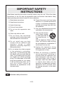
1) Read these instructions.
2) Keep these instructions.
3) Heed all warnings.
4) Follow all instructions.
5) Do not use this apparatus near
water.
6) Clean only with dry cloth.
7) Do not block any ventilation
openings. Install in accordance with
the manufacturer’s instructions.
8) Do not install near any heat
sources such as radiators, heat
registers, stoves, or other
apparatus (including amplifiers)
that produce heat.
9) Do not defeat the safety purpose
of the polarized or grounding-
type plug. A polarized plug has
two blades with one wider than the
other. A grounding-type plug has
two blades and a third grounding
prong. The wide blade or the third
prong are provided for your safety.
If the provided plug does not fit
into your outlet, consult an
electrician for replacement of the
obsolete outlet.
10) Protect the power cord form being
walked on or pinched particularly
at plugs, convenience receptacles,
and the point where they exit from
the apparatus.
11) Only use attachments/accessories
specified by the manufacturer.
12) Use only with the cart,
stand, tripod, bracket,
or table specified by
the manufacturer, or
sold
with the apparatus. When a cart is
used, use caution when moving
the cart/apparatus combination to
avoid injury from tip-over.
13) Unplug this apparatus during
lightning storms or when unused
for long periods of time.
14) Refer all servicing to qualified
service personnel. Servicing is
required when the apparatus has
been damaged in any way, such
as power-supply cord or plug is
damaged, liquid has been spilled
or objects have fallen into the
apparatus, the apparatus has been
exposed to rain or moisture, does
not operate normally, or has been
dropped.
Read these operating instructions carefully before using the unit. Follow the safety
instructions on the unit and the applicable safety instructions listed below. Keep
these operating instructions handy for future reference.
IMPORTANT SAFETY
INSTRUCTIONS
indicates safety information.

- 4 (E) -
ENGLISH
Information on Disposal for Users of Waste Electrical & Electronic Equipment
(private households)
This symbol on the products and/or accompanying documents means that used
electrical and electronic products should not be mixed with general household
waste.
For proper treatment, recovery and recycling, please take these products to
designated collection points, where they will be accepted on a free of charge
basis. Alternatively, in some countries you may be able to return your products to
your local retailer upon the purchase of an equivalent new product.
Disposing of this product correctly will help to save valuable resources and prevent any potential
negative effects on human health and the environment which could otherwise arise from
inappropriate waste handling.
Please contact your local authority for further details of your nearest designated collection point.
Penalties may be applicable for incorrect disposal of this waste, in accordance with national
legislation.
For business users in the European Union
If you wish to discard electrical and electronic equipment, please contact your dealer or supplier
for further information.
Information on Disposal in other Countries outside the European Union
This symbol is only valid in the European Union.
If you wish to discard this product, please contact your local authorities or dealer and ask for the
correct method of disposal.

- 5 (E) -
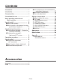
Contents
Accessories
Accessories .......................................... 5
Introduction ...........................................
6
Characteristics ...................................... 6
Precautions for use ..............................
7
Ma jor operating controls and
their functions .................................. 8
How to install ......................................
12
How to set the lens ........................ 12
Ho w to install on the camera housing,
pan/tilt head, tripod, etc. ............
12
Ho w to set up the system ..................
13
Co nfiguration example 1: Connection
of camera controller ..................
13
Co nfiguration example 2:
High-speed P/T system ............. 14
Operation procedure ..........................
15
How to adjust ......................................
16
Fl ange back adjustment
(for zoom lens) ............................
16
Lens iris gain volume adjustment .. 16
White balance adjustment ............. 17
Co lor temperature and white balance
adjustment (reference) ..............
17
Black balance adjustment ............... 18
Gen-lock adjustment ...................... 18
Setting of menu items ........................
19
How to display the menus .............. 19
TOP menu ...................................... 19
MAINTENANCE menu ................. 20
SETTING menu ............................ 36
CAMERA ID menu ....................... 43
FILE OPERATION menu .............. 44
TIME CODE menu ....................... 45
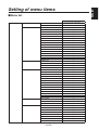
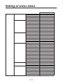
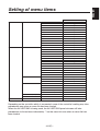
Menu list ......................................... 46
Appearance ......................................... 49
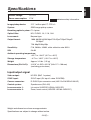
Specifications ..................................... 50
Appendix ............................................. 51
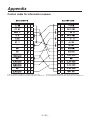
Co ntrol cable for
information camera .......................
51
Lens cap ................................................. 1
Filter ........................................................ 2

- 6 (E) -
ENGLISH
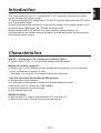
Introduction
Characteristics
New 2/3˝ 1 million-pixel CCD is employed. [1280(H)720(V)]
1 million-pixel CCD is 2/3˝ in size, being compact and light-weight.
Multiple HD formats supported
Signal output of many different formats enabled by incorporating a format conversion
circuit in Panasonic’s original LSI chip.
Fabrication of a circuit for 24 Hz-based formats also supported.
14-bit A/D conversion and brand-new DSP featured
Wide dynamic range achieved
Crystal-clear shooting even of images with different brightness levels
Boosting of gain to a maximum 72 dB enabled
Electronic extender function provided
Cine gamma supported
Multiple functions
Multi-function DTL such as high-luminance DTL and skin DTL.
Right and left, top and bottom picture reversing function.
This camera employs new 2/3˝ 1 million-pixel IT CCD, realizing a compact light-weight
system including the optical system.
The newly developed CCD image sensor, 14-bit A/D converter and brand-new DSP make
for a wide dynamic range.
The self-contained format conversion circuit ensures support for a multiple number of HD
formats including 1080/59.94i, 50i, 720/60p, 59.94p and 50p.
Making the best use of the features of a small-sized self-contain camera, it is
accommodated in the camera housing and able to provide high-quality HD pictures as an
multi purpose digital camera.

- 7 (E) -
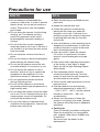
Do not attempt to disassemble the
camera or other units. In order to prevent
electric shock, do not remove screws or
covers. There are no user-serviceable
parts inside.
Do not abuse the camera. Avoid striking,
shaking, etc. The camera contains
sensitive components which could
be damaged by improper handling or
storage.
Do not let the lens remain uncapped
when the camera is not use. If the lens is
not installed, do not leave the lens mount
hole uncovered.
Do not touch the surface of the lens or
prism.
Do not use strong of abrasive detergents
when cleaning the camera body.
Do not aim the camera toward the sun,
no matter whether it is turned on or not.
Do not expose the camera to rain or
moisture, and do not try to operate the
equipment in wet conditions. Do not
operate the camera if it becomes wet.
Do not operate the camera outdoors
during a lightning storm.
Do not use the camera in an extreme
environment where high temperatures or
high humidity exist.
Do not leave the camera turned on when
not in use. Do not unnecessarily turn the
camera power on and off repeatedly. Do
not block the ventilation slots.
Do not cover the port otherwise block
ventilation during operation. Internal heat
buildup can cause a fire.
Refer any servicing to qualified service
personnel.
Handle the camera with care.
Protect the precision made lens by
placing the lens cap over when the
camera is not in use. If the lens is not
installed, protect the surface of the prism
by placing the body cap into the lens
mount hole.
Use a mild blower or lens cleaning tissue
designed for coated lenses, to clean the
surface of the lens or prism in the event
that it should become dirty.
Use a dry cloth to clean the camera
if it is dirty. In case the dirt is hard to
remove, use mild detergent and wipe
gently.
Use caution when operating the camera
in the vicinity of spot lights or bright
lights, as well as light reflecting objects
and surfaces.
Take immediate action if ever the
camera should become wet. Turn the
power off and have the unit checked by
an authorized service facility.
Follow normal safety precaution to avoid
personal injury.
Use the camera in an environment
where the temperature is within 32°F
– +104°F (0°C – +40°C), and the relative
humidity is within 30% – 90% (no
condensation).
Always turn the power off when the
camera is not going to be used. Operate
the camera only when there is adequate
ventilation.
Cooling fan
There is internally provided a cooling fan.
Since the cooling fan is a consumable
part, replace it after about 30,000 hours
of operation.
(Be sure to ask the dealer for the
replacement.)
Precautions for use
DON’TS DO’S

- 8 (E) -
ENGLISH
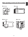
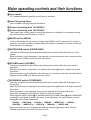
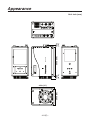
Major operating controls and their functions
Front view Top view
Bottom view Rear view

- 9 (E) -
Major operating controls and their functions
Lens mount
2/3” standard bayonet type (B4 mount) lens is installed.
Lens fixing ring knob
Lens is fixed by turning the knob clockwise.
Camera mounting hole (1/4-20UNC)
Camera mounting hole (3/8-16UNC)
The screw holes can be used to secure the camera for installing it on camera housing,
and when using a pan/tilt head or a tripod.
MENU switch [MENU]
A menu will appear on the monitor screen when MENU switch is pressed for at least 3
seconds. The menu screen is cleared when the switch is pressed for at least 3 seconds
while the menu is displayed.
ENTER/AWB switch [ENTER/AWB]
The item just below can be selected by pressing this switch while the menu is on the
screen.
When the menu is not displayed or the camera is in shooting mode, the automatic white
balance control (AWB) can be set with this switch.
UP/ABB switch [UP/ABB]
The item just above can be selected by pressing this switch while the main menu is
displayed.
While the Sub menu is displayed, any setting can be brought up to a higher value with
this switch.
When the menu is not displayed or the camera is in shooting mode, the automatic black
balance control (ABB) can be set with this switch.
DOWN/BAR switch [DOWN/BAR]
The item just below can be selected by pressing this switch while the Sub menu is on
the screen.
While the Sub menu is displayed, any setting can be brought down to a lower value with
this switch.
When the menu is not displayed, the color bar and the shooting conditions are
alternately indicated by pressing the switch for about 5 seconds.
Each time the MENU switch
is pressed while the UP/ABB switch and DOWN/BAR
switch
is held down and while the menu is not displayed, the video output format is
changed in the following sequence.
720/60p 720/59.94p 720/50p 1080/60i 1080/59.94i 1080/50i
1080/30p 1080/29.97p 1080/25p 1080/24p 1080/23.98p
When the video format is changed, the operate indicator
flashes twice with the
720/60p format and once with any other format.

- 10 (E) -
ENGLISH
HD SDI output connector [HD SDI OUT]
SDI signal output is given by this line.
G/L input connector [G/L IN]
For gen-lock with the camera, the external sync signal (black burst) or tri-level sync
signal is supplied to this input connector.
Cable clamp
Clamp the DC power supply cable connected to the DC 12 V input connector to
prevent it from slipping out.
Optional card slot
Slot for inserting an optional card. For details, refer to the manual for optional cards.
Cooling fan
• Do not block or obstruct the ventilation during operation. It may otherwise cause
internal heating or fire.
• The life of this fan is approximately 50,000 hours (at room temp. 77°F (25°C)).
Replace the fan as needed.
(When the room temperature is higher than 95°F (35°C), replace the fan 30% earlier.)
Be sure to ask the dealer for the replacement.
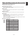
Interface connector [I/F]
Pin No. Signal
1 Gen-lock signal GND
2 Time code signal input
3 Not used
4 TX_N (EIA422)/TXD (EIA232) output
5 RX_N (EIA422)/RXD (EIA232) output
6 Camera power supply input (DC +12 V)
7 Gen-lock signal input
8 GND
9 TX_P (EIA422) output
10 RX_P (EIA422) input
11 GND
12 Time code signal GND
13 GND
14 GND
15 GND
Major operating controls and their functions
5
1
6
10
15
11

- 11 (E) -
Tally output connector [TALLY OUT]
The R tally and G tally signals are output from this connector.
These signals take effect when the optional card for studio applications has been
inserted.
Pin No. Signal
1 GND
2 R_TALLY_OUT
3 G_TALLY_OUT
4 +12 V (500 mA Max)
IRIS connector [IRIS]
Used to connect the IRIS control cables of the lens.
Pin No. Signal Pin No. Signal
1 Return control 7 Iris follow
2 VTR-S/S 8 Iris auto selection
3 UNREG GND 9 —
4 Iris manual selection 10 Zoom position information
5 Iris control 11 Focus position information
6 UNREG 12 V 12 NC
Zoom/Focus connector [ZOOM/FOCUS]
Used to connect the zoom/focus control cables of lens.
Pin No. Signal Pin No. Signal
1 Focus control selection 7 COM
2 Zoom control selection 8 Focus control
3 GND 9 Zoom control
4 Forcible iris closing 10 Iris control selection
5 Iris control 11 COM +Voltage
6 +Voltage 12 COM –Voltage
Operate indicator
Green LED lamp lights to indicate that the specified DC power is supplied to
the DC 12 V input connector
.
When the video format is changed, the operate LED flashes twice when the format is
720/60p and once with any other format.
DC 12 V input connector [DC12V IN]
12 V DC is supplied through the optional DC power supply cable (AW-CA4T1).
Major operating controls and their functions

- 12 (E) -
ENGLISH
How to install
Be sure to ask the dealer for the installation,
adjustment and connection of this equipment.
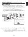
How to set the lens
Standard 2/3” bayonet type (B4 mount) lens of any makers can be used*.
Turn the lens fixing ring knob counterclockwise to remove the lens mount cap.
Set the lens in place, and turn the lens fixing ring knob clockwise to precisely fix the
lens.
Connect the iris control cable to the IRIS connector.
Connect the zoom/focus control cable to the ZOOM/FOCUS connector.
* Note that there are some lenses uncontrollable with respect to zoom, focus function.
How to install on the camera housing, pan/tilt head, tripod, etc.
Precisely set the camera on the camera housing, pan/tilt head, tripod, etc. by using
the camera set-screw hole (1/4-20UNC, 3/8-16UNC).
When mounting the camera on a pan/tilt head, be sure to use proper tools and make
sure that there is no fear of falling off.
Attach the provided filter to the iris
control cable and zoom/focus control
cable.
Zoom/focus control cable
(to ZOOM/FOCUS connector)
(When a pan/tilt head is
used, connect the cable
to the pan/tilt head.)
Iris control
cable (to IRIS
connector)
Lens fixing ring
knob
Filter

- 13 (E) -
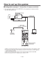
How to set up the system
Configuration example 1: Connection of camera controller
Use multi cable supplied with AK-HRP150G for the connection of camera controller
AK-HRP150G and this unit.
Before connecting the cables, be sure to set the power switch of AC adapter to OFF.
Connect the multi cable to the interface connector of the camera, and the opposite
side to camera controller.
Set the AC adapter power switch to ON, then the camera can be controlled.
After shooting, set the AC adapter power switch to OFF.
AK-HC1500G
ULTI FORMAT
DIGITAL CAMERA SYSTEM
Multi cable
(POWER + CONTROL)
Lens
Multi purpose camera
AK-HC1500G
Camera controller
AK-HRP150G
AC adapter
AW-PS505A
Monitor
HD SDI OUT
IRIS

- 14 (E) -
ENGLISH
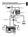
How to set up the system
Configuration example 2: High-Speed P/T system
Cable kit
AW-CAK4HIG
Lens
Multi purpose camera
AK-HC1500G
Monitor
IRIS
HD SDI
AC adapter
AW-PS505A
ZOOM/FOCUS
Indoor pan/tilt head
AW-PH400
Pan/tilt control panel
AW-RP400
Camera
controller
AK-HRP150G
HD SDI
AC adapter
AW-PS505A
Cable kit
AW-CAK4HIG
(Camera control)
10BASE-T straight cable
(Pan/tilt control)

- 15 (E) -
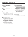
Operation procedure
1
Turn on the power of each
equipment.
2
Properly adjust the light for the
object.
3
Adjust the flange back of the lens,
the iris and the focus.
Flange back must be adjusted when
the camera is used for the first time
or after replacement of the lens.
4
Adjust the white balance.
This adjustment is needed when the
camera is used for the first time or
after leaving unused for a long time.
The adjustment is necessary when
the lighting condition or brightness is
changed.
After adjusting the white balance
once, re-adjustment is not needed
under the same condition.
5
Adjust the black balance.
This adjustment is needed when the
camera is used for the first time or
after leaving unused for a long time.
The adjustment is necessary when
the ambient temperature is greatly
changed or at the change of season.
After adjusting the black balance
once, re-adjustment is not needed
under the same condition.
6
Start shooting.
(After shooting, be sure to turn off the
power of each equipment connected.)

- 16 (E) -
ENGLISH
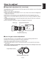
How to adjust
Flange back adjustment (for zoom lens)
The adjustment is to adjust the focus in all the range from the maximum zoom to the widest
angle of the zoom lens.
Shoot a dark object to open the iris.
Adjust the distance from the object to 6.6 ft. (2 m) at least, then loosen the flange back
fixing knob of the lens.
Set the lens to the maximum zoom and adjust the focus by turning the focus ring.
Set the lens to the widest angle and adjust the focus by turning the flange back adjust
ring.
Repeat adjusting the focus ring and flange back adjust ring until the focus is adjusted
within the zooming range.
After finishing the adjustment, tighten the flange back fixing knob.
Lens iris gain volume adjustment
Iris gain adjust hole (G or S) is provided at front of the lens housing. Adjust the iris
according to the following procedure by using a screwdriver.
Set the iris select switch of the lens to A “AUTO” side.
Turn the iris gain adjust volume to maximize the gain in such extent that no hunting
takes place.
* When CAM is selected as the IRIS MODE setting on the camera menu, IRIS gain on the menu
can be used to make adjustments.
Iris gain adjust volume
Auto iris power zoom lens
Flange back adjust ring
Focus ring Flange back fixing knob

- 17 (E) -
How to adjust
White balance adjustment
Adjust the white balance after shooting a white object by at least 50% of the screen.
NOTE: If the white signal level is over 100% or less than 50%, the white balance may not
be normally adjusted.
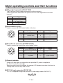
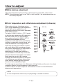
Color temperature and white balance adjustment (reference)
When carbon is burnt, it develops various
colors of light depending on the temperature.
Natural light can be specified by color
temperature reflecting to the color developed
when carbon is burnt.
The light of 3,200K (K=Kelvin, –273°C equals
to absolute zero temperature 0K) represents
the same value (color) as what develops
when carbon is burnt at 3,200K (2,927°C).
The relationship between the color
temperature of the light source and weather
condition is indicated in the right figure. Let’s
study the difference of shooting an indoor
object from shooting one outdoors. Studios
are usually lighted with incandescent lamps
and the color temperature of a white object in
a studio is around 3,000K. The color
temperature of a white object outdoors is
around 6,500K. The former may look a little
yellowish while the latter appears somewhat
bluish when they are shot by a camera.
However, the human eye does not recognize
color differences among these objects even
under different ambient lighting conditions,
because of their adaptability to light.
The video camera reproduces color differences with high fidelity and the color of an object
somewhat different from what appears to the human eye.
Therefore, there is a need to adjust the white balance in order to correct differences
between color temperatures.
NOTE
Color temperature outdoors may vary depending on weather conditions.
Blue sky
Partly cloudy
Fluorescent lamp
Cloudy
AWC
Fine
Tangsten lamp
Halogen lamp
Rainy
Candle

- 18 (E) -
ENGLISH
Black balance adjustment
Adjust it with the lens closed.
When the motor drive lens is controlled from the camera, adjusting the black balance
causes the lens to be automatically closed.
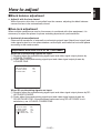
Gen-lock adjustment
When multiple cameras are used or the camera is combined with other equipment, it is
necessary to adjust the phase for phase matching by external synchronization.
Horizontal phase adjustment
Observe the waveforms of externally synchronizing signal input (black burst signal) and
video signal output by a two-phenomenon oscilloscope, and make the horizontal phase
according to the camera menu.
Adjustment with GEN-LOCK of SETTING menu
When HD synchronizing signals are input:
Roughly adjust the synchronizing signal input and video signal output phases by
H PHASE-COARSE.
Finely adjust the synchronizing signal input and video signal output phases by
H PHASE-FINE.
When SD synchronizing signals are input:
Roughly adjust the synchronizing signal input and video signal output phases by SD-
HD PHASE-COARSE.
Finely adjust the synchronizing signal input and video signal output phases by
SD-HD PHASE-FINE. If the adjustment performed using SD-HD PHASE is not
satisfactory, use H PHASE-COARSE/FINE.
How to adjust
��
GEN-LOCK
��
GEN-LOCK INPUT :BNC
H PHASE-COARSE :+00
H PHASE-FINE :+000
GEN-LOCK
GEN-LOCK INPUT :BNC
H PHASE-COARSE :+00
H PHASE-FINE :+000
SD HD PHASE CRS :+0
SD HD PHASE FINE :+00

- 19 (E) -
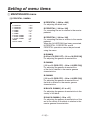
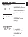
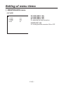
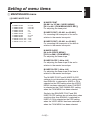
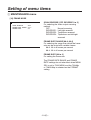
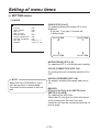
Setting of menu items
How to display the menus
Two methods are used to display the menus.
Using AK-HC1500G multi purpose camera to display the menus:
Hold down the MENU switch on the rear panel of the main unit for at least 3 seconds
to display the TOP menu.
Use the UP/DOWN switch to move the cursor to the target item, and press the
ENTER switch to move to a menu at a lower hierarchical level.
Using AK-HRP150G camera controller
Press the MENU ON/OFF switch on the AK-HRP150G so that its lamp lights. The
TOP menu now appears.
Move the cursor to the target item, and press the MENU switch to move to a menu at
a lower hierarchical level.
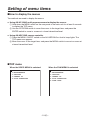
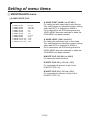
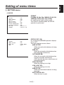
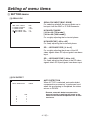
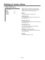
TOP menu
When the VIDEO MENU is selected: When the FILM MENU is selected:
USER MENU
1.MAINTENANCE
2.SETTING
3.CAMERA ID
4.FILE OPERATION
USER MENU (FILM MENU)
1.MAINTENANCE
2.SETTING
3.CAMERA ID
4.FILE OPERATION
5.TIME CODE
Page is loading ...
Page is loading ...
Page is loading ...
Page is loading ...
Page is loading ...
Page is loading ...
Page is loading ...
Page is loading ...
Page is loading ...
Page is loading ...
Page is loading ...
Page is loading ...
Page is loading ...
Page is loading ...
Page is loading ...
Page is loading ...
Page is loading ...
Page is loading ...
Page is loading ...
Page is loading ...
Page is loading ...
Page is loading ...
Page is loading ...
Page is loading ...
Page is loading ...
Page is loading ...
Page is loading ...
Page is loading ...
Page is loading ...
Page is loading ...
Page is loading ...
Page is loading ...
-
 1
1
-
 2
2
-
 3
3
-
 4
4
-
 5
5
-
 6
6
-
 7
7
-
 8
8
-
 9
9
-
 10
10
-
 11
11
-
 12
12
-
 13
13
-
 14
14
-
 15
15
-
 16
16
-
 17
17
-
 18
18
-
 19
19
-
 20
20
-
 21
21
-
 22
22
-
 23
23
-
 24
24
-
 25
25
-
 26
26
-
 27
27
-
 28
28
-
 29
29
-
 30
30
-
 31
31
-
 32
32
-
 33
33
-
 34
34
-
 35
35
-
 36
36
-
 37
37
-
 38
38
-
 39
39
-
 40
40
-
 41
41
-
 42
42
-
 43
43
-
 44
44
-
 45
45
-
 46
46
-
 47
47
-
 48
48
-
 49
49
-
 50
50
-
 51
51
-
 52
52


Panasonic AK-HC1500G User manual
- Category
- Bridge cameras
- Type
- User manual
Ask a question and I''ll find the answer in the document
Finding information in a document is now easier with AI
Related papers
-
Panasonic AK-HC910L User manual
-
-
-
-
-
-
-
-
-
Panasonic AW-RP50E User manual
Other documents
-
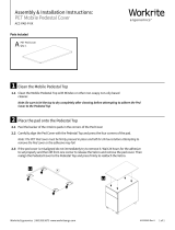 Workrite Ergonomics PET Mobile Pedestal Cover Installation guide
-
Workrite PET Mobile Pedestal Cover Installation guide
-
 DRS Technologies DRS WatchMaster IP Ultra 6000 30 Hz User manual
-
Sony BRCZ330 User manual
-
Sony BRC-H800 User manual
-
 Anton/Bauer AJ-HDX400E User manual
-
Orion Safety Products 8907 Specification
-
Sony HXC-D70 Operating instructions
-
-


