Page is loading ...

User Manual
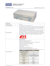
ACS-1208L
ACS-1216L
2002-01-15

Note: This equipment has been tested and found to comply with
the limits for a Class A digital device pursuant to Part 15 of the
FCC Rules. These limits are designed to provide reasonable
protection against harmful interference when the equipment is
operated in a commercial environment. This equipment
generates, uses, and can radiate radio frequency energy and, if
not installed and used in accordance with the instruction manual,
may cause harmful interference to radio communications.
Operation of this equipment in a residential area is likely to cause
harmful interference, in which case the user will be required to
correct the interference at his own expense.
2002-01-15

Packing List
The complete Master View ACS-1208L / ACS-1216L package consists of:
M 1 ACS-1208L or ACS-1216L KVM Switch
M 2 Custom KVM Cable Sets
M 1 Power Adapter with Power Cord
M 1 User Manual
M 1 Quick Start Guide
M 1 LCD OSD Quick Reference
Check to make sure that the unit was not damaged in shipping. If you encounter
a problem, contact your dealer.
Read this manual thoroughly and follow the installation and operation
procedures carefully to prevent any damage to the unit, and/or any of the
devices connected to it.
© Copyright 2001 ATEN
®
International Co., Ltd.
Manual Part No. PAPE-0201-1AT
Printed in Taiwan 12/2001
All brand names and trademarks are the registered property of their respective owners.
2002-01-15
ACS-1208L / ACS-1216L User Manual iii.

Contents
Overview . . . . . . . . . . . . . . . . . . . . . . . . . . . . . . . . . . . . . . . . . . . . . . . . . . . . . . 1
Features. . . . . . . . . . . . . . . . . . . . . . . . . . . . . . . . . . . . . . . . . . . . . . . . . . . . . . . 2
Hardware Requirements . . . . . . . . . . . . . . . . . . . . . . . . . . . . . . . . . . . . . . . . . . 3
Computers . . . . . . . . . . . . . . . . . . . . . . . . . . . . . . . . . . . . . . . . . . . . . . . . . . 3
Cables . . . . . . . . . . . . . . . . . . . . . . . . . . . . . . . . . . . . . . . . . . . . . . . . . . . . . 3
Introduction . . . . . . . . . . . . . . . . . . . . . . . . . . . . . . . . . . . . . . . . . . . . . . . . . . . . 4
ACS-1208L / ACS1216L Front View . . . . . . . . . . . . . . . . . . . . . . . . . . . . . . 4
ACS-1208L / ACS1216L Rear View . . . . . . . . . . . . . . . . . . . . . . . . . . . . . . 6
Installation . . . . . . . . . . . . . . . . . . . . . . . . . . . . . . . . . . . . . . . . . . . . . . . . . . . . . 7
Before you Begin . . . . . . . . . . . . . . . . . . . . . . . . . . . . . . . . . . . . . . . . . . . . . 7
Single Station Installation. . . . . . . . . . . . . . . . . . . . . . . . . . . . . . . . . . . . . . . 7
Daisy Chaining. . . . . . . . . . . . . . . . . . . . . . . . . . . . . . . . . . . . . . . . . . . . . . . 8
Operation. . . . . . . . . . . . . . . . . . . . . . . . . . . . . . . . . . . . . . . . . . . . . . . . . . . . . 10
Hot Plugging. . . . . . . . . . . . . . . . . . . . . . . . . . . . . . . . . . . . . . . . . . . . . . . . 10
Powering Off and Restarting . . . . . . . . . . . . . . . . . . . . . . . . . . . . . . . . . . . 10
Port ID Numbering . . . . . . . . . . . . . . . . . . . . . . . . . . . . . . . . . . . . . . . . . . . 11
Port Selection. . . . . . . . . . . . . . . . . . . . . . . . . . . . . . . . . . . . . . . . . . . . . . . 11
Hotkeys . . . . . . . . . . . . . . . . . . . . . . . . . . . . . . . . . . . . . . . . . . . . . . . . . . . . . . 12
Hotkey Port Control . . . . . . . . . . . . . . . . . . . . . . . . . . . . . . . . . . . . . . . . . . 12
Hotkey Beeper Control. . . . . . . . . . . . . . . . . . . . . . . . . . . . . . . . . . . . . . . . 15
Hotkey Summary Table . . . . . . . . . . . . . . . . . . . . . . . . . . . . . . . . . . . . . . . 15
OSD Operation . . . . . . . . . . . . . . . . . . . . . . . . . . . . . . . . . . . . . . . . . . . . . . . . 16
OSD Overview . . . . . . . . . . . . . . . . . . . . . . . . . . . . . . . . . . . . . . . . . . . . . . 16
OSD Navigation . . . . . . . . . . . . . . . . . . . . . . . . . . . . . . . . . . . . . . . . . . . . . 17
OSD Main Screen Headings . . . . . . . . . . . . . . . . . . . . . . . . . . . . . . . . . . . 17
OSD Functions. . . . . . . . . . . . . . . . . . . . . . . . . . . . . . . . . . . . . . . . . . . . . . 18
Appendix . . . . . . . . . . . . . . . . . . . . . . . . . . . . . . . . . . . . . . . . . . . . . . . . . . . . . 27
ACS-1208L - Computer Connection Table . . . . . . . . . . . . . . . . . . . . . . . . 27
ACS-1216L - Computer Connection Table . . . . . . . . . . . . . . . . . . . . . . . . 27
Removing the KVM Module. . . . . . . . . . . . . . . . . . . . . . . . . . . . . . . . . . . . 28
OSD Factory Default Settings . . . . . . . . . . . . . . . . . . . . . . . . . . . . . . . . . . 29
Troubleshooting . . . . . . . . . . . . . . . . . . . . . . . . . . . . . . . . . . . . . . . . . . . . . 29
Specifications. . . . . . . . . . . . . . . . . . . . . . . . . . . . . . . . . . . . . . . . . . . . . . . 30
Limited Warranty . . . . . . . . . . . . . . . . . . . . . . . . . . . . . . . . . . . . . . . . . . . . 31
2002-01-15
iv. ACS-1208L / ACS-1216L User Manual

Overview
The Master View ACS-1208L and ACS-1216L KVM Switches are control units that
allow access to multiple computers from a single console (keyboard, mouse, and
monitor). Before the development of the Master View, the only way to control
multiple computer configurations from a single console was through a complex and
costly network system. Now, with the Master View ACS-1208L and ACS-1216L,
you can easily access multiple computers in a cost effective manner.
A single Master View ACS-1208L or ACS-1216L can control up to 8 or 16
computers, respectively. As many as 31 additional Master View ACS-1216 units
can be daisy chained to each other, so that up to 512 computers can all be
controlled from a single keyboard-monitor-mouse console.
The Master View ACS-1208L / ACS-1216L offers a space-saving, streamlined
approach to KVM switch technology by integrating a keyboard, LCD monitor,
and trackball in a 1U high Slideaway housing for convenient rack mounting.
Slide the KVM module section out; flip the cover up; and you are ready to go to
work. The LCD display is built into the cover; the keyboard and trackball are
built into the base. When finished, simply flip the cover down and slide the KVM
module away.
For further convenience, the ACS-1208L / ACS-1216L features high density 15
pin connectors instead of the usual 25 pin connectors. This space-saving
innovation allows a full, 16 port switch to be installed in a 1U system rack.
Because of its modular design, the KVM section can be detached from the
switch section. If you ever need to expand your connections, you can remove
the 8 port Switch module; and replace it with a 16 port Switch module.
Setup is fast and easy; plugging cables into their appropriate ports is all that is
entailed. Because the ACS-1208L / ACS-1216L intercepts keyboard input
directly, there is no software to configure, so there is no need to get involved in
complex installation routines or be concerned with incompatibility problems.
Access to any computer connected to the installation is easily accomplished
either by entering Hotkey combinations from the keyboard, or by means of a
powerful menu driven OSD (On Screen Display) system. A convenient Auto
Scan feature also permits automatic scanning and monitoring of the activities of
all computers running on the installation one by one.
There is no better way to save time and money than with a Master View
ACS-1208L / ACS-1216L installation. By using the Master View ACS-1208L /
ACS-1216L with its Slideaway console, to manage your installation, you: (1)
eliminate the expense of having to purchase a separate keyboard, monitor, and
mouse for each computer; (2) save all the space those extra components would
take up; (3) save the space that a keyboard, monitor, and mouse would take
with a standard KVM switch; (4) save on energy costs; and (5) eliminate the
inconvenience and wasted effort involved in constantly moving from one
computer to another.
2002-01-15
ACS-1208L / ACS-1216L User Manual 1

Features
w Integrated KVM Console - Including a 15" LCD Monitor - In a 1U High
Slideaway Housing For Convenient Rack Mounting
w Space Saving Technology - A Single Console Controls Up To 8 (ACS-1208L)
or 16 (ACS-1216L) Computers
w Daisy Chain Up To 31 Additional Units - Control Up to 512 Computers From
the Unit’s Integrated Slideaway Console
w Console Detaches From the Switch Chassis for Easy Maintenance
w No Software Required - Convenient Computer Selection via Hotkeys and
Intuitive On Screen Display (OSD) Menus
w Auto Scan Feature for Monitoring User-Selected Computers
w Hot Pluggable - Add or Remove Computers Without Having To Power Down
the Switch
w Auto-Sensing of Station Position on Daisy Chained Installations - No Need
For Manual DIP Switch Setting - Front Panel LED Indicates Station Position
w Port Names Automatically Reconfigured When Station Sequence Is Changed
w Two Level Password Security - Only Authorized Users View and Control the
Computers - Up to Four Users Plus an Administrator - Separate Profiles For Each
w Two Level Logout - Manual and Timed
w PS/2 Keyboard and Mouse Emulation - Computers Boot Even When the
Console Focus is Elsewhere
w Superior Video Quality - Supports Resolutions of Up To 1024 x 768
w Rack Mountable in 19" System Rack (1U)
2002-01-15
2 ACS-1208L / ACS-1216L User Manual

Hardware Requirements
Computers
The following equipment must be installed on each computer:
w A VGA, SVGA or Multisync card.
Note: Since the integrated LCD monitor’s maximum resolution is 1024 x
768, make sure that the computer resolution settings do not exceed
1024 x 768.
w A 6-pin mini-DIN (PS/2 style) mouse port.*
w Either a 6-pin mini-DIN (PS/2 Style) keyboard port with +5V DC on pin 4 and
Ground on pin 3, or a 5-pin DIN (AT Style) keyboard port with +5V DC on pin
5 and ground on pin 4.*
* See the note under Cables in the next section.
Cables
Substandard cables may damage the connected devices or degrade overall
performance. For optimum signal integrity and to simplify the layout, we strongly
recommend that you use the following high quality CS Custom Cable sets:
Function CS Part Number
Master View to Computer 2L-5201P - 1.2 m
2L-5202P - 1.8 m
2L-5203P - 3.0 m
Master View to Master View (Daisy Chaining) 2L-1700 - 0.6 m
2L-1701 - 1.8 m
Note: 1. The ACS-1208L/ACS1216L does not support serial mice. You cannot
use Serial-to-PS/2 adapters with the extender cables. Attempts to do
so will not work.
2. If your computer uses an AT style keyboard socket you will need to
purchase a PS/2-to-AT keyboard adapter (Part No. 2A-106, or any
standard keyboard adapter), in order to plug the cable into the
computer’s keyboard port.
2002-01-15
ACS-1208L / ACS-1216L User Manual 3

Introduction
ACS-1208L / ACS1216L Front View
1. Handle
Pull to slide the KVM module out; push to slide the module in.
2. Cover
After sliding the KVM module out, flip up the cover to access the LCD
monitor, keyboard and trackball.
3. Port LEDs
Port LEDs provide status information about their corresponding CPU Ports.
The top row of LEDs corresponds to Ports 1 - 8; the bottom row corresponds
to Ports 9 - 16. There are two LEDs for each Port. The one on the left is the
On Line LED; the one on the right is the Selected Port LED:
w An On Line LEDs light ORANGE to indicate that the computer attached to
the corresponding port is up and running.
w A Selected LEDs light GREEN to indicate that the computer attached to
the corresponding port is the one that has the KVM focus. The LED is
steady under normal conditions, but flashes when its port is accessed
under Auto Scan Mode (see F7 SCAN, p. 26).
Note: 1. Since the ACS-1208L only has eight ports, only the top row of
LEDs (corresponding to Ports 1 - 8) are active on that unit. On the
ACS-1216L, both rows are active.
2. When the ACS-1208L / ACS-1216L is first powered on, the On Line
and Selected LEDs blink one after the other as the Switch performs
a self-test.
1
2
3
5
6
4
2002-01-15
4 ACS-1208L / ACS-1216L User Manual

4. Rack Mounting Brackets
There are rack mounting brackets attached to each corner of the unit. They
are used to secure the chassis to a system rack.
5. LCD Display Controls
The LCD On/Off Switch is located here, as well as buttons to control the
position and picture settings of the LCD display. See the LCD OSD Quick
Reference (provided with this package) for details.
6. Locking Tabs
There is a locking tab on each side of the unit. When the KVM module is
pulled all the way out, these tabs pop out to lock it in place. Before you can
slide the KVM module back into the chassis, you must first push these tabs in.
2002-01-15
ACS-1208L / ACS-1216L User Manual 5

ACS-1208L / ACS1216L Rear View
1. Daisy Chain Port
When Daisy Chaining Units, the cable plugs in here.
2. CPU Port Section
The cables that link to the computers plug in here.
Note: The shape of these 15-pin connectors has been specifically modified
so that only extender cables designed to work with this switch can
plug in (see the Cables section on p. 3, for details). Do NOT attempt
to use ordinary 15 pin VGA connector cables to link these ports to the
computers.
3. Power Port
The power adapter cable plugs in here.
1
2
3
1
2
3
2002-01-15
6 ACS-1208L / ACS-1216L User Manual

Installation
Before you Begin
1. Make sure that power to all the devices you will be connecting
up have been turned off.
2. To prevent damage to your equipment due to ground potential
difference, make sure that all devices on the installation are properly
grounded. Consult your dealer for technical details, if necessary.
Single Station Installation
In a Single Stage installation, there are no additional Master View’s daisy
chained down from the first unit. To set up a single stage installation do the
following:
1. Use connector cable sets (as described in the Cables section on p. 3), to
connect any available CPU Port to the Keyboard, Video and Mouse ports of
the computer you are installing.
Note: Ignore the Daisy Chain Port at this time. It is only used when daisy
chaining additional Master View units. Daisy chaining is described in
the next section.
2. Plug the power adapter cable into the Master View’s Power Jack, then plug
the power adapter into an AC power source.
3. Turn on the power to the computers.
2002-01-15
ACS-1208L / ACS-1216L User Manual 7

Daisy Chaining
To control even more computers, up to 31 additional Master View ACS-1208 /
ACS-1216 units can be daisy chained down from the First Station.
Note: The ACS-1208 and ACS-1216 are similar in all respects to the
ACS-1208L and ACS-1216L, except that they come in standard
housings. They do not have the built in Slideaway console.
As many as 504 (ACS-1208L) or 512 (ACS-1216L) computers can be controlled
from from the unit’s integrated Slideaway console in a complete installation.
Tables showing the relation between the number of computers and the number
of Master Views needed to control them are provided on p. 27 in the Appendix.
To set up a daisy chained installation, do the following:
1. Make sure that power to all the devices you will be connecting up has been
turned off.
2. Use a daisy chain cable set (described in the Cables section, p. 3), to
connect the Chain Out port of the parent unit to the Chain In port of the child
unit.
3. Use connector cable sets (described in the Cables section, p. 3), to connect
any available Master View CPU Port to the Keyboard, Video and Mouse
ports of the computers you are installing.
4. Repeat the above steps for any additional Master View units you wish to add
to the chain.
5. Power up the installation according to the following procedure:
1. Plug in the power adapter for the First Station.
Wait a few seconds for the unit to ascertain its Station ID.
2. Plug in the power adapters for each Station on the installation in turn
(Second Station, then Third Station, etc.).
Each ACS-1208 and ACS-1216 has a LED display on its front panel to
indicate its Station ID (the Station ID for the First Stage unit is 01, the ID
for the Second Stage unit is 02, the ID for the Third Stage unit is 03, etc.).
In each case, wait for the Station ID to be ascertained and displayed on
the Station ID LED before plugging in the next Station.
3. After all the Stations are up, power on the computers.
2002-01-15
8 ACS-1208L / ACS-1216L User Manual

ACS-1216L
ACS-1216
ACS-1216
2002-01-15
ACS-1208L / ACS-1216L User Manual 9

Operation
Hot Plugging
The ACS-1216L supports hot plugging - components can be removed and
added back into the installation by unplugging their cables from the ports without
the need to shut the unit down. In order for Hot Plugging to work properly,
however, these procedures that must be followed:
M
Switching Station Positions:
You can switch station positions by simply unplugging from the old parent
and plugging into a new one. After you do, in order for the OSD menus to
correspond to the change, you must reset the OSD. See RESET STATION
IDS, p. 24, for details.
Note: If the computer’s Operating System does not support hot plugging,
this function may not work properly.
M
Hot Plugging CPU Ports:
In order for the OSD menus to correspond to the change, you must manually
reconfigure the OSD information for the new Port information. See the F3
SET (p. 20) and F4 ADM (p. 22), functions for details.
Powering Off and Restarting
If it becomes necessary to Power Off one of the Master View units, before
starting it back up you must do the following:
1. Shut down all the computers that are attached to it.
2. Wait 10 seconds, then plug the Master View back in.
3. After the Master View is up, Power On the computers.
Note: If you have shut down more than one Station, power up the highest
Station first and work your way down to the lowest one.
2002-01-25
10 ACS-1208L / ACS-1216L User Manual

Port ID Numbering
Each CPU port on a Master View installation is assigned a unique Port ID. The
Port ID is made up of two parts: a Station Number, and a Port Number:
w The Station Number - a two digit number which reflects the ACS-1208L /
ACS-1216L’s position in the daisy chain sequence. This corresponds to the
number displayed on the front panel Station ID LED.
w The Port Number - a two digit number which reflects the port on the
ACS-1208L / ACS-1216L Station that the computer is connected to.
w The Station Number precedes the Port Number.
w Station and Port numbers from 1 - 9 are padded with a preceding zero, so
they become 01 - 09.
For example, a computer attached to Port 6 of Station 12 would have a Port ID
of: 12-06.
Port Selection
Port Selection is accomplished either by entering Hotkey combinations from the
keyboard, or by means of the ACS-1208L / ACS-1216L’s OSD (On Screen
Display). Hotkey Port Selection is discussed in the next section; OSD Operation
is discussed in detail beginning on p. 16.
2002-01-15
ACS-1208L / ACS-1216L User Manual 11

Hotkeys
Hotkey Port Control
Hotkey Port Control allows you to provide KVM focus to a particular computer
directly from the keyboard. The Master View ACS-1208L / ACS-1216L provides
the following Hotkey Port Control features:
w Selecting the Active Port
w Auto Scanning
w Previous/Next Switching
w
Invoking Hotkey Mode
1. All Hotkey operations begin by invoking Hotkey Mode. Invoking Hotkey Mode
takes three steps: 1) Press and hold down the Num Lock key; 2) Press and
release the minus key; 3) Release the Num Lock key:
[Num Lock] + [-];
Note: The minus key must be released within one half second, otherwise
Hotkey invokation is cancelled and it has no effect.
2. When Hotkey Mode is active:
w A Command Line appears on the monitor screen. The command line
prompt is the word Hotkey: in yellow text on a blue background, and
displays the subsequent Hotkey information that you key in.
w Ordinary keyboard and mouse functions are suspended - only Hotkey
compliant keystrokes and mouse clicks (described in the sections that
follow), can be input.
3. Pressing [Esc] exits Hotkey Mode.
2002-01-15
12 ACS-1208L / ACS-1216L User Manual

w
Selecting the Active Port
Each CPU port is assigned a Port ID (see Port ID Numbering, p. 11). You
can directly access any computer on the installation with a Hotkey
combination that specifies the Port ID of the CPU Port that the computer is
connected to. The steps involved are:
1. Invoke Hotkey Mode with the [NumLock] + [-] combination
2. Key in the Port ID
The Port ID numbers display on the Command Line as you key them in. If
you make a mistake, use [Backspace] to erase the wrong number.
3. Press [Enter]
After you press [Enter], the KVM focus switches to the designated
computer and you automatically exit Hotkey Mode.
w
Auto Scanning
Auto Scan automatically switches among all the active CPU Ports that are
accessible to the currently logged on User (see Scan/Skip Mode of the OSD
F3 SET function, p. 21), at regular intervals, so that he can monitor their
activity automatically.
Setting the Scan Interval:
The amount of time Auto Scan dwells on each port is set with the Scan
Duration setting of the OSD F3 SET function (see p. 21). You can change the
scan interval before activating Hotkey Auto Scanning, if you wish, with the
following Hotkey combination:
1. Invoke Hotkey Mode with the [NumLock] + [-] combination
2. Key in [T] [n]
Where [T] is the letter T, and [n] is a number from 1-255 that represents
the number of seconds for the dwell time.
The letter T, and the numbers display on the Command Line as you key
them in. If you make a mistake, use [Backspace] to erase the wrong
number.
3. Press [Enter]
After you press [Enter], you automatically exit Hotkey Mode, and are ready
to invoke Auto Scanning.
2002-01-15
ACS-1208L / ACS-1216L User Manual 13

Starting Auto Scan:
To start Auto Scanning, key in the following Hotkey combination:
1. Invoke Hotkey Mode with the [NumLock] + [-] combination
2. Key in [A]
After you press A, you automatically exit Hotkey Mode, and enter Auto
Scan Mode.
3. To exit Auto Scan Mode, press [Esc] or [Spacebar]
Note: While Auto Scan Mode is in effect, ordinary keyboard and mouse
functions are suspended - only Auto Scan Mode compliant
keystrokes and mouse clicks can be input. You must exit Auto
Scan Mode in order to regain normal control of the console.
w
Skip Mode
This feature allows you to switch between computers in order to monitor
them manually. You can dwell on a particular port for as long or as little as
you like - as opposed to Auto Scanning, which automatically switches after a
fixed interval. To invoke Previous/Next Switching, key in the following Hotkey
combination:
1. Invoke Hotkey Mode with the [NumLock] + [-] combination
2. Key in [Arrow]
Where [Arrow] refers to the left or right Arrow key. After you press [Arrow],
you automatically exit Hotkey Mode, and enter Skip Mode where you can
switch ports as follows:
← Skips from the current port to the first accessible port previous to it. (See
Scan/Skip Mode, p. 21, for information regarding accessible ports.)
→ Skips from the current port to the next accessible port.
↑ Skips from the current port to the last accessible port of the previous
Station.
↓ Skips from the current port to the first accessible port of the next Station.
Note: 1. Once Skip Mode has been invoked, until you exit, you can keep
on skipping simply by pressing an Arrow key. You don’t have to
use the [NumLock] + [-] combination again.
2. While Skip Mode is in effect, ordinary keyboard and mouse
functions are suspended - only Skip Mode compliant keystrokes
can be input. You must exit Skip Mode in order to regain normal
control of the console.
3. To exit Skip Mode, press [Esc]
2002-01-15
14 ACS-1208L / ACS-1216L User Manual

Hotkey Beeper Control
The Beeper (see Activate Beeper, p. 23) can be Hotkey toggled On and Off.
To toggle the Beeper, key in the following Hotkey combination:
1. Invoke Hotkey Mode with the [NumLock] + [-] combination
2. Key in [B]
After you press [B], the Beeper toggles On or Off. The Command Line
displays Beeper On or Beeper Off for one second; then the message
disappears and you automatically exit Hotkey Mode.
Hotkey Summary Table
Combination Action
[Num Lock] + [-] [Port ID] [Enter] Switches access to the computer that corresponds
to that Port ID.
[T] [n] [Enter] Sets the Auto Scan interval to n seconds - where n
is a number from 1 - 255.
[A] Invokes Auto Scan Mode.
[←]
Invokes Skip Mode and skips from the current port
to the first accessible port previous to it.*
[→]
Invokes Skip Mode and skips from the current port
to the next accessible port.*
[↑]
Invokes Skip Mode and skips from the current port
to the last accessible port of the previous Station.*
[↓]
Invokes Skip Mode and skips from the current port
to the first accessible port of the next Station.*
[B] Toggles the Beeper On or Off.
* Once Skip Mode has been invoked, until you exit, you can keep on skipping
simply by pressing an Arrow key. You don’t have to use the [NumLock] + [-]
combination again.
2002-01-15
ACS-1208L / ACS-1216L User Manual 15

OSD Operation
OSD Overview
The On Screen Display (OSD) is used to handle all computer control and
switching procedures. All procedures start from the OSD Main Menu. To pop up
the Main Menu, tap the [Scroll Lock] key twice.
Note: You can optionally change the Hotkey to the Ctrl key (see OSD Hotkey,
p. 20), in which case you would tap [Ctrl] twice. With this method, the
[Ctrl] keys must be on the same side (both left, or both right).
The OSD incorporates a two level (Administrator / User) password system. Before
the OSD Main Screen comes up, a dialog box appears that asks you to provide
your password. If the password function has been set, you must provide the
password in order to access the OSD Main Screen.
If this is the first time that the OSD is being run, or if the password function has
not been set, simply press [Enter]. The OSD Main Screen comes up in
Administrator Mode. In this mode, you have administrator privileges, with
access to all Administrator and User functions, and can set up operations
(including password authorization for the future), as you would like.
When you invoke the OSD, a screen similar to the one below appears:
Note: 1. The diagram depicts the Administrator’s Main Screen. The User Main
Screen does not show the F4 and F6 functions, since these are reserved
for the Administrator and can’t be accessed by ordinary Users.
2. OSD always starts in List view, with the highlight bar at the same
position it was in the last time it was closed.
3. Only the ports that have been set accessible by the Administrator for
the currently logged in User are visible (see SET ACCESSIBLE
PORTS, p. 24, for details).
F1:GOTO F3:SET F5:SKP F7:SCAN X
F2:LIST F4:ADM F6:BRC F8:LOUT
z
z
z
ADMINISTRATOR
LIST:ALL
SN PN QV NAME
01 14 ATEN INTL.CO. 1
01 15 ATEN INTL.CO. 2
01 16 ATEN INTL.CO. 3
02 01 FAX SERVER 1
02 02 FAX SERVER 2
02 03 WEB SERVER 1
02 04 WEB SERVER 2
02 05 MAIL SERVER 1
2002-01-15
16 ACS-1208L / ACS-1216L User Manual
/