7
Heat Controller Multi-Position Air Handler with Hydronic Heat with X13 Motor HWCGxxX0A
Counter Flow Installation
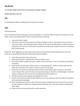
Fig.7. Air Handler parts and changes for Counter flow
• Before positioning the Air Handler in the counter
flow position, remove lower access panels, filter
panel and filter.
• Remove the A-Coil assembly with the horizontal
drain pan; discard the horizontal drain pan (not
required for counter flow application).
• Rotate the Air Handler 180° to the counter flow
position.
• Remove the coil deck and filter channel, rotate
the filter channels 180° and re-attach in the
same location they were removed from.
• Rotate the coil deck 180° and re-attach in the
holes near the center of the cabinet (screws not
provided).
• Slide the A-coil assembly into the cabinet on the
coil deck (without the horizontal drain pan).
Note: Push the coil pan assembly all the way to
the rear of the cabinet until it locks under the
bracket in the rear.
• Place the 3” x 16” counter flow plates at the
outside bottom of the coil as shown in FIG. 8.
• Replace the access panels and filter panel.
Fig.8. Position of plates required in counter flow
Electrical Installation
These units are designed for single or three phase 120
volts, 60 Hz power supply. Wire selection and wiring
must be in accordance with the National Electric Code
(or CEC for Canadian Installations) and/or local codes.
Unit terminals are designed to accommodate copper and
aluminum wirings. If aluminum wiring is used; please
observe special precautions relative to sizing, wire
connections and corrosion protection.
Fig.9 shows the typical electrical connections reqruired
for A/C only and heat pump applications.
The unit ships with a micro-processor based board
which controls the electrical functining of the unit. An
inspection of the controls is recommended prior to start
up of the unit.
Fig.10 provides a schematic of the control board present
in the unit. The units ship from the factory with the
aquastat jumper in the OFF position (right two pins) and
the heating selector in the HW position (right two pins). If
an aquastat is used in the application; the jumper should
be changed to ON position (left two pins).
Note: Terminals T and N located on the top right side
of the board are not intended for field use and should be
left un-connected.
The aquastat (AQ) jumper must be
in the OFF position at all times; except when an aquastat
is used. If the jumper is moved to the ON position
without installing an aquastat the blower will not be
energized.
When an aquastat is present, the blower will be
energized at the aquastat temperature settings.
Fig 9. Electric connections
This model is shipped without
factory a installed pump, therefore the two black wires
should be connected to the boiler terminals T T. In
applications where a boiler provides the hot water
supply, these wires shouId be connected to the boiler.
Terminals T T are normally open dry contacts.
In applications where a valve is used to regulate hot
water supply, the two black wires located on the T T
terminals should be removed and placed on the two
terminals reading “VALVE”. The open ends of the wires
should be connected to the valve according to local
requirments and instructions of the valve manufacturer.
On call for heat, 24V will be sent to the field installed
valve or pump relay.
On call for heat water will circulate through the water
(hydronic) coilfor 60 secs prior to energizing the blower.
After the thermostat is satisfied, the blower will continue
to stay energized for a minimum of 30 secs. This helps
maximize heating efficiency.
The freeze protection sensor is connected to the FP and
R terminals. These are normally open and will close
when the sensor sees 40ºF. The pump stays ON for a
minimum of 30 secs.
The board has a built-in timer which circulates hot water
6 times a day for 60 secs each time to prevent the coil
from freezing.
Fig.10. Micro-processor control board
Start up
Ensure motor is pre-loaded with program from factory.
WARNING
The hot water (hydronic) coil and
all water lines MUST be purged of air prior to starting the
pump. Failure to do so could result in pump damage.
Manufacturer will not be responsible for any property
damage or physical injury caused by failure to follow this
instruction.
WARNING
Hot water flowing to the coil
should be in the range of 120º - 180º F. Water at these
temperatures can cause first-degree burns. Use of
proper safety gear while installing or servicing the
equipment is strongly recommended as is installation of
a water-tempering valve (for water temperatures of
above 140ºF) to supply lower temperature water to
fixtures in the house. N170L series or equivalent should
be used.
Connect the hydronic coil to the water heater system as
shown in Fig 11. Use flexible piping and insulate all
pipes. Plumbing must be in compliance with state or
local codes (Code CMR248 in Massachusetts). The
units for hydronic heat have different top and heater box
configurations. This configuration is not suitable for
electric heat. DO NOT try to install a hydronic heater in a
unit not equipped for it. Verify connections: hot water to
“in” and cold water to “out”. 7/8” ODstubs are provided
for plumbing connections. Bleed the air flow system
through the bleeder port or optional valve.
Purging The System
1) Open air vent and allow water heater to fill with
water. Close air vent when water heater is full and
all air has been purged.
2) Ignite water heater. Set thermostat on water heater
to 140 degrees.
3) Close the valve on the hot water supply from the
water heater ("A") and open the valve on the cold-
water return to the water heater ("B"). Then open the
air vent in the fan coil. Use a bucket or hose to
discard water during purging process at air bleed
valve. Purge air completely from line.
4) Once air is purged, close return valve ("B") and open
supply valve ("A"). Purge the coil and lines of air
completely.
5) After air is purged from the system and filled with
water, open the return valve ("B") and the supply
valve ("A"). Then close the air vent in the fan coil.
6) Apply power to the fan coil and set the room
thermostat on heat. Raise the temperature setting to
activate the circulating pump
7) Check the pump to ensure proper operation. The
water inlet of the unit should be hot if the water
temperature in the water heater has reached the set
point. If water is not being circulated through the coil
but the pump is running, then open the air bleed
valve in the unit and purge any air left in the system.