Dometic 3314080 CCC2 Operating instructions
- Category
- Thermostats
- Type
- Operating instructions
This manual is also suitable for
Dometic 3314080 CCC2 is the most advanced RV thermostat designed for ease of operation and many years of reliable service.
Product Capabilities:
- Liquid Crystal Display (LCD)
- Two operation programs
- Constant time of day display
- Remote Sensor (precise comfort control)
- Display reminder for air filter maintenance
- Independent climate control for up to four zones
- Modes of operation: OFF, Cool, Heat Pump, Fan, Heat Strip, Auto, Furnace or Aqua
- Adjustable fan speed: Auto, Low, Med, High
- Compressor delay
- System reset
Possible Use Cases:
- Set different temperatures in separate areas of your RV (up to four zones)

USA
SERVICE OFFICE
Dometic Corporation
1120 North Main Street
Elkhart, IN 46514
CANADA
Dometic Corporation
46 Zatonski, Unit 3
Brantford, ON N3T 5L8
CANADA
For Service Center &
Dealer Locations
Please Visit:
www.eDometic.com
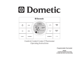
COMFORT CONTROL CENTER 2 THERMOSTAT
OPERATING INSTRUCTIONS
REVISION B
Form No. 3314149.018 08/16
(French 3314169.016_B)
©2016 Dometic Corporation
LaGrange, IN 46761
PROGRAMMABLE THERMOSTAT
MODEL
3314080.000 BLACK
3314080.015 WHITE

2
TABLE OF CONTENTS
INTRODUCTION ........................................................................................................................................... 2
DOCUMENT SYMBOLS ...............................................................................................................................3
ABOUT YOUR NEW THERMOSTAT ............................................................................................................3
A. Features ....................................................................................................................................3
B. SystemConguration&Initialization ......................................................................................... 3
C. QuickReferenceToControlButtons .........................................................................................5
D. Quick Reference To LCD Icons .................................................................................................5
PROGRAMMING&OPERATIONS ............................................................................................................... 6
A. ON/OFF ..................................................................................................................................... 6
B. ClockSetting .............................................................................................................................6
C. Temperature Format °F / °C ...................................................................................................... 7
D. Inside Temperature .................................................................................................................... 7
E. ZoneSelection ...........................................................................................................................8
F. ModeSelection .......................................................................................................................... 8
G. Fan Speed ................................................................................................................................. 9
H. Temperature Set-Point ............................................................................................................... 9
MODE DESCRIPTION ................................................................................................................................10
A. “OFF” - Off Mode .....................................................................................................................10
B. “COOL”-CoolMode ...............................................................................................................10
C. “HP” - Heat Pump Mode .......................................................................................................... 10
D. “HS” - Heat Strip Mode ............................................................................................................ 11
E. “FAN” - Fan Mode .................................................................................................................... 11
F. “FURN” / “AQUA” - Furnace Or Aqua (Hydronic) Heating Mode ............................................. 11
G. “AUTO” - Auto Change Over Mode .........................................................................................12
SPECIAL FEATURES.................................................................................................................................. 12
A. Auto Fan .................................................................................................................................. 12
B. ZoneControl ............................................................................................................................ 13
C. Program“1”&“2” .....................................................................................................................13
D. ExamplesOfTimesProgrammed ............................................................................................ 15
E. CANbus Interface ....................................................................................................................15
F. AuxiliaryHeat(HeatPumpModelsOnly) ................................................................................ 16
G. StageSelect-TwoAirConditioner/HeatPumpUnits(SelectModels)OnOneZone ............. 16
H. StageSelect-DualCompressorAirConditioner/HeatPump(SelectModels) ....................... 16
I. Auto Generator Start (AGS) ....................................................................................................17
J. Load Shed ..............................................................................................................................17
K. DefrostCycle(HeatPumpModelsOnly) .................................................................................17
L. CompressorTimeDelay .......................................................................................................... 17
M. PowerInterruption ...................................................................................................................18
N. LCD Error Code ....................................................................................................................... 18
SYSTEM RESET PROCEDURE ................................................................................................................. 19
GENERAL INFORMATION .......................................................................................................................... 19
INTRODUCTION
Congratulations! Your recreational vehicle manufacturer has equipped your RV with
themostadvancedRVthermostat.YourDometicComfortControlCenter2thermostat
(hereinafter referred to as the CCC 2 thermostat) has been designed for ease of opera-
tionandformanyyearsofreliableservice.
DometicCorporationreservestherighttomodifyappearancesandspecicationswithout
notice.

3
A. Reduce Heat Gain ................................................................................................................... 19
B. Disclaimer ................................................................................................................................ 19
MAINTENANCE ..........................................................................................................................................20
A. AirFilter ...................................................................................................................................20
B. Dometic CCC 2 Thermostat ....................................................................................................20
SERVICE ..................................................................................................................................................... 20
TABLE OF CONTENTS
DOCUMENT SYMBOLS
Indicatesadditionalinformationthatisnotrelatedtopersonalinjury.
Indicates step-by-step instructions.
ABOUT YOUR NEW THERMOSTAT
A. Features
● LiquidCrystalDisplay
● Twooperationprograms
● Constanttimeofdaydisplay
● RemoteSensor(Precisecomfortcontrolwithin1°Fofset-point)
● Displayreminderletsyouknowwhentoserviceorreplacelters
● Uptofourindependentzones
TohelpfamiliarizeyourselfwiththeoperationoftheCCC2thermostat,reviewthe
followingdiagramsandaccompanyingtextthatexplainthefunctionalcharacteris-
tics of this system.
YourCCC2thermostatisequippedwithaliquidcrystaldisplay(LCD)thatidenties
themodeofoperation(OFF,Cool,HeatPump, Fan,HeatStrip,Auto,&Furnace
orAqua), temperature set-point, zone identication (“1”, “2”, “3”, “4”), fan speed
(“Auto,” “Low,” “Med,” “High”), program “1” and “2”, inside temperature, clock,
°F/°C,compressordelay,andltermaintenance.Themodesofoperationviewed
intheLCDwillvarydependingonthesysteminstalledinyourRV.
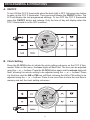
B. System Conguration & Initialization
Theinstallerof your systemwillsetthe required systemDIPswitches totheON
position.InorderfortheCCC2thermostattorecognizethesystemzones,typeof
unitsinstalledandtheiroptions,asystemresetmustbedone.

4
Oncethesystemiscompletelyinstalled,doasystemreset:
1. Make sure the CCC 2 thermostat is in the OFF mode. See section, “C. Quick
ReferenceToControlButtons”onpage(5).
2. SimultaneouslypressandholdtheMODE and ZONE buttons. See section, “C.
QuickReferenceToControlButtons”onpage(5).
3. TheLCDwilldisplay“IniT”andallavailablezones.
4. ReleasetheMODE and ZONE buttons.
5. Press the ON/OFF button to exit system set up.
6. The furnace ON/OFF temperature differential should be set at this time. For
furtherinformationonfurnacemodedifferentialsetting,seesection,“F.“FURN”
/ “AQUA” - Furnace Or Aqua (Hydronic) Heating Mode” on page (11).
Anytimeasystemresetoccurs,thefactorydefaultsettingsarerestored.Seetable,
“Factory Preset Settings” on page (4).
IntheunlikelyeventofCCC2systemmemorylossordipswitchsettingchange,the
CCC2thermostatwillrequireasystemreset.Forsystemresetprocedure,seemain
heading, “System Reset Procedure” on page (19).
YourDometicCCC2thermostathasbeenpre-programmed.Reviewsettingsbelow
andadjustthesettingstoyourpersonalcomfortlevel.
AnytimetheCCC2isinanidlestage(notilluminated)youwillneedtowakeit
upbypressinganybuttonontheCCC2beforeitwillrecognizeanewsetting
attempt.
Factory Preset Settings Factory Preset Settings Each Zone
All Zones Program “1”
Function Setting Function Setting
TimeofDay(Clock) — — — Heating 68 °F / 20 °C
Each Zone Cooling 72 °F / 22 °C
Automatic 70 °F / 21 °C
Heating 68 °F / 20 °C Fan Speed Auto
Cooling 72 °F / 22 °C Mode Off
Automatic 70 °F / 21 °C Time 8:00AM
Fan Speed Auto Program “2”
Mode Off Heating 68 °F / 20 °C
Cooling 72 °F / 22 °C
Automatic 70 °F / 21 °C
Fan Speed Auto
Mode Off
Time 10:00PM
ABOUT YOUR NEW THERMOSTAT

5
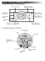
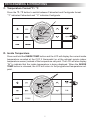
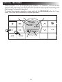
C. Quick Reference To Control Buttons
Press to display
inside temperature
Press to select
temperature format
Press to decrease
temperature set-point
Press to increase
temperature set-point
Press to select zone
Press to select
On and OFF
Press to select
fan speed
Press to set
clock
Press to
select mode
Press to select
program 1 or 2
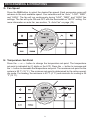
D. Quick Reference To LCD Icons
Temperature
Set-Point or Error
Code
Operation Mode
Time of Day
Fan Speed
Zone
Program
Clean or Replace
Filter
Compressor
Delay
ABOUT YOUR NEW THERMOSTAT

6
PROGRAMMING & OPERATIONS
A. ON/OFF
ToturnONtheCCC2thermostatwhenthebacklightisOFF,rstpressanybutton
towakeuptheCCC2thermostat.ThenpressandreleasetheON/OFF button. The
LCDwilldisplaythelastprogrammedsettings.ToturnOFFtheCCC2thermostat
press the ON/OFFbuttonandrelease.Onlythetimeofdaywilldisplaywhenthe
CCC 2 thermostat is in the OFF condition.
B. Clock Setting
Press the CLOCKbuttontoinitiatetheclocksettingsub-menuontheCCC2ther-
mostat. When in this menu, the hourdigitswillashrst.Thehourcanbeadjusted
using the
∧
or
∨
buttons. Press the CLOCK button again and the minutedigitswill
ash,allowingtheminutesettingtobeadjustedusingthe
∧
or
∨
buttons. Press
it a third time and the AM or PMiconwillash,allowingtheAMorPMsettingtobe
adjustedusingthe
∧
or
∨
buttons.Pressitonemoretimetostorethenewtimein
memoryandexittheclocksettingsub-menu.

7
C. Temperature Format °F / °C
Press the °F / °CbuttontoswitchbetweenFahrenheitandCentigradeformat.
“°F” indicates Fahrenheit and “°C” indicates Centigrade.
D. Inside Temperature
PressandholdtheINSIDE TEMPbuttonandtheLCDwilldisplaythecurrentinside
temperaturerecorded at the CCC 2thermostat (or at theoptional remote indoor
temperaturesensor)insteadofthetemperatureset-point.TheLCDwillalsodisplay
“IN”toindicate that theinsidetemperatureisbeing displayed. When theINSIDE
TEMPbuttonisreleased,theLCDwillreturntotheprogrammedtemperatureset-
point.
PROGRAMMING & OPERATIONS

8
E. Zone Selection
Press the ZONEbuttontocycletheLCDdisplaythroughtheavailablezoneselec-
tions;“Zone1”,“Zone2”,“Zone3”,and“Zone4”.Onlytheavailablezonesinstalled
within your system will display. For more information on zones, see section, “B.
ZoneControl”onpage(13).
F. Mode Selection
Press the MODE button and the LCD will display the rst available mode. Each
successivepresswill advance tothenextavailablemode. Continue to pressthe
MODEbuttonuntilthedesiredmodeappears.Dependingonthesystemsinstalled,
yourchoiceswillbe“OFF”,“COOL”,“AUTO”,“HP”,“FURN”or“AQUA”,“HS”,and
“FAN”. For more information on modes, see main heading, “Mode Description” on
page (10).
PROGRAMMING & OPERATIONS

9
G. Fan Speed
Press the FANbuttontoselectthedesiredfanspeed.Eachsuccessivepresswill
advancetothenextavailablespeed.Yourselectionswillbe“Auto”,“LOW”,“MED”,
and“HIGH”.Thefanwillruncontinuouslyduring“LOW”, “MED”, and “HIGH” fan
settings.ThefanwillcycleONandOFFwiththethermostaton“AUTO”setting.For
more information on auto fan, see section, “A. Auto Fan” on page (12).
H. Temperature Set-Point
Press the
∧
or
∨
button to change the temperature set-point. The temperature
set-point is indicated by (2) digits on the LCD. Press the
∧
button to increase and
the
∨
button to decrease the temperature set-point. The maximum set-point for the
system is 90 °F (32 °C). The minimum set-point is determined by the active operat-
ingmode.Forheating,theminimumis40°F(4°C)andminimumforcoolingis55
°F (13 °C).
PROGRAMMING & OPERATIONS

10
MODE DESCRIPTION
A. “OFF” - Off Mode
DisplaysOFFmodeinazone.
B. “COOL” - Cool Mode
In the COOLmodethesystemwillcyclethecompressorONandOFFbasedon
the room air temperature and the temperature set-point on the CCC 2 thermostat.
Whenthesystemcallsforcoolingtherewillbeadelayofapproximately2minutes.
Duringthisdelay,thehourglassiconwillbedisplayedintheLCD.Inautofan,the
fanwillturnONrstfollowedbythecompressorinapproximately15seconds.In
thismodethereare(4)fanspeedselections:
LOW: Thefanoperatescontinuouslyatlowspeed.ThecompressorcyclesONand
OFF.
MED: Thefanoperatescontinuouslyatmediumspeed.ThecompressorcyclesON
and OFF.
HIGH: Thefanoperatescontinuouslyathighspeed.The compressor cycles ON
and OFF.
AUTO: Whenautofanisselectedthefanspeedwillvarydependingonthediffer-
encebetweenthetemperatureset-pointandtheroomtemperature.Inautofanthe
compressorandthefanwillcycleONandOFFwiththethermostat.Thecompressor
shutsOFFrstfollowedbythefaninapproximately15seconds.Formoreinforma-
tion on auto fan, see section, “A. Auto Fan” on page (12).
C. “HP” - Heat Pump Mode
In the HPmodethesystemwillcyclethecompressorONandOFFbasedonthe
room air temperature and the temperature set-point on the CCC 2 thermostat.
Whenthesystemcallsforheatingtherewillbeadelayofapproximately2minutes.
Duringthisdelay,thehourglassiconwillbedisplayedintheLCD.Inautofan,the
compressorwillturnONrstfollowedbythefaninapproximately15seconds.In
thismodethereare(4)fanspeedselections:
LOW: Thefanoperatescontinuouslyatlowspeed.ThecompressorcyclesONand
OFF.
MED: Thefanoperatescontinuouslyatmediumspeed.ThecompressorcyclesON
and OFF.
HIGH: Thefanoperatescontinuouslyathighspeed.The compressor cycles ON
and OFF.
AUTO: Whenautofanisselectedthefanspeedwillvarydependingonthediffer-
encebetweenthetemperatureset-pointandtheroomtemperature.Inautofanthe
compressorandfanwillcycleONandOFFwiththethermostat.Thecompressor
shutsOFFrstfollowedbythefaninapproximately15seconds.Formoreinforma-
tion on auto fan, see section, “A. Auto Fan” on page (12).

11
D. “HS” - Heat Strip Mode
In the HSmodethesystemwillcycletheheatstripONandOFFbasedontheroom
air temperature and the temperature set-point on the CCC 2 thermostat. In this
modethereare(4)fanspeedselections:
LOW: Thefanoperatescontinuouslyatlowspeed.TheheatstripcyclesONand
OFF.
MED: Thefanoperatescontinuouslyatmediumspeed.TheheatstripcyclesON
and OFF.
HIGH: Thefanoperatescontinuouslyathighspeed.TheheatstripcyclesONand
OFF.
AUTO: ThefanoperatesinlowspeedandwillcycleONandOFFwiththethermo-
stat.
E. “FAN” - Fan Mode
In FANmodethereare(4)fanspeedselections:
LOW: Thefanoperatescontinuouslyatlowspeed.
MED: Thefanoperatescontinuouslyatmediumspeed.
HIGH: Thefanoperatescontinuouslyathighspeed.
AUTO: ThefanwillbeOFF.
F. “FURN” / “AQUA” - Furnace Or Aqua (Hydronic) Heating Mode
(Factory setting is “FURN”)
Tochangethesettingfrom“FURN”to“AQUA”orviceversa,simultaneouslypress
the
∧
and
∨
buttons.TheLEDwilldisplaytheselectedoption.
In the FURN / AQUAmodethesystemwillcycle theRV’sfurnace/aquaONand
OFF based on the room air temperature and the temperature set-point on the CCC 2
thermostat.ThesystemcanbeconguredtooperateusinganON/OFFdifferential
of either 1 °F / °C or 2 °F / °C. This feature is programmed during the system ini-
tialization.Seesection,“B.SystemConguration&Initialization”onpage(3).
Tosetthe1°F/°Cdifferential,simultaneouslypressthePROGRAM button and the
∧
button(“dIF1”willappearinthedisplaywhilethebuttonsarepressed).Tosetthe
2°F/°Cdifferential,simultaneouslypressthePROGRAM button and the
∨
button
(“dIF2”willappearinthedisplaywhilethebuttonsarepressed).Inthismodethere
are(4)fanspeedselections:
LOW: Thefanoperatescontinuouslyatlowspeed.
MED: Thefanoperatescontinuouslyatmediumspeed.
HIGH: Thefanoperatescontinuouslyathighspeed.
AUTO: The fan is OFF.
MODE DESCRIPTION

12
G. “AUTO” - Auto Change Over Mode
In the AUTOmodethesystemwillautomaticallychangethemodeofoperationfrom
cooltoheatorfromheattocool.Inorderforthismodetooperate,thezonebeing
programmed must contain either a heat pump, heat strip or furnace heating source.
When in the AUTOmode,allpre-programmedoperationsfortheheatpump,heat
strip,andfurnacewillapply.
Auto Change Over Cooling: If the room temperature rises above the temperature
set-pointby2°F /°C,theairconditionerwillturnONuntiltheroomtemperature
reachesthetemperatureset-pointatwhichtimetheairconditionerwillcycleOFF.
Auto Change Over Heating: Iftheroomtemperaturegoesbelowthetemperature
set-pointby2°F/°C,theavailableheatsourcewillbecycledONuntiltheroom
temperaturereachesthetemperaturesetpointatwhichtimeitwillcycleOFF.
Ifmorethanoneheatsourceisavailableonthiszone,thepriorityforselectingthe
heatsourcewillbeheatpump(rst),furnace(second),andheatstrip(third).
SPECIAL FEATURES
A. Auto Fan
When“AUTO”fanisselected,thefanspeedwillvarydependingonthedifference
betweenthetemperatureset-pointandtheroomtemperature.In“AUTO”fan,the
compressorandfanwillcycleONandOFFwiththethermostat.
Whenthedifferenceis:
8 °F / °C or more The fan operates on HIGH
5 to 7 °F / °C The fan operates on MED
4°F/°Corless ThefanoperatesonLOW
MODE DESCRIPTION

13
B. Zone Control
ZonesareestablishedatthetimeoftheinstallationofyourDometicCCC2thermo-
stat.Azoneisanareaofcooling/heatingwhichiscontrolledindependentlybythe
CCC2thermostat.TheCCC2thermostat allowsforfourzones(AirConditioner/
Heat Pump) to be set up and run independent of each other. If you have one air
conditioner/heatpumpinstalled,youwillhaveonezone.IfyourRVhasmorethan
onecooling/heatingsystem,youmayhavetwo,three,orfourzones.
YourCCC2thermostatwilloperatecoolingandheatingappliancesthatyourvehicle
manufacturerhasdesignedtocoolorheatspecicareas(zones)ofyourRV.The
CCC2thermostatwilladviseyouofthenumberofzonesinyourRV.Thezonesare
displayed“1”,“2”,“3”,or“4”intheLCDreadout.Seesection,“D.QuickReference
To LCD Icons” on page (5).
Inthe event your vehicle hasmultiple zones designed, you havethe freedom of
selectingdifferentmodesofoperationsforeachzone.Tochangefromonezoneto
another, press the ZONE button on the CCC 2 thermostat. Each time the button is
pressedandreleasedtheindicatorwillchangethezonedatadisplayed.Whenthe
zoneshavebeenprogrammed,thezonesinoperationwillbedisplayed.Toprogram
eachzone,simplyrepeattheprogrammingstepsshownundermainheading,“Pro-
gramming&Operations”onpage(6).
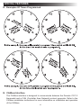
C. Program “1” & “2”
TheDometicCCC2thermostatcanstoretwooperatingprograms.Eachprogram
canbesetonindividualzoneswithdifferentmodeandtimesettingsforeachzone.
For each event the user can program the operating mode, fan speed, temperature
set-point, and the time of day for the event.
1. Selectthezonetobeprogrammed.
2. Selectprogram“1”bypressingthePROGRAMbutton.“PROG1”iconwillblink
ontheLCDdisplay.
3. Press the CLOCK button to set the time of day for program to start.
4. Press the MODEbuttontoselectthemodeofoperation.
5. Press the FANbuttontoselectthefanspeed.
6. Press the PROGRAMbuttontosavethe“PROG1”settings.LCDwillnowdis-
play“PROG2”.
To set program “2”, repeat steps (3) through (5).
7. Press the PROGRAM button again to save program(s) in memory.
Dependingonthetimeofday,program“1”or“2”willbeginimmediately.
Forinstance,ifprogram“1”issettobeginat10:00AMandthetimeofday
is10:30AM,program“1”willbeginimmediately.Ontheotherhand,ifpro-
gram“1”issetto10:00AMandprogram“2”issettobeginat6:00PMand
thetimeofdayis7:00PM,program“2”willbeginimmediately.

14
Whenprogram“1”or“2”isoperating,the“PROG1”or“PROG2”iconwillbedis-
playedintheLCD.Thezonewillcontinuetooperateintheprogrammedsettinguntil
theprogramismanuallycancelled.
Tocanceltheprogramoperation,pressandholdthePROGRAM button for 3 sec-
onds.Thezonewillberestoredtonormaloperation.
SPECIAL FEATURES

15
SPECIAL FEATURES
D. Examples Of Times Programmed
E. CANbus Interface
TheCANbusinterface is designedtocommunicatebetween the DometicCCC2
thermostatandaCAN(ControllerAreaNetwork)protocolgenerator.Refertothe
CANbusinstallationinstructionsformoreinformationoninstallationandoperation
of the CANbus.

16
F. Auxiliary Heat (Heat Pump Models Only)
Auxiliaryheat operation will beactivated when the measured temperatureof the
outdoortemperaturesensorislessthan30°F(-1°C).Ifthesystemisequippedwith
afurnace,thecontrolwillselectFURNheatingmodefortheauxiliaryheatsource.
Auxiliaryheatoperation,onceinitiated,willhavepriorityoveraheatpumpdefrost
cycle.Auxiliaryheatoperationwillbede-activatedandtheheatpumpoperationwill
resume when the temperature of the outdoor temperature sensor is higher than
35 °F (2 °C).
G. Stage Select - Two Air Conditioner/Heat Pump Units (Select Models)
On One Zone
Thissystemcanbeconguredtoruntwoairconditioner/heatpumpunitsusingthe
sametemperatureset-pointforcontrollingthecomfortlevelinonezone.Oneunitis
designated as the primary stage and the other unit is designated as the secondary
stage.ThepowermoduleboardsinbothunitswillusethesameDIPswitchselec-
tionfortheZone(forexample,bothwillbesetto“Zone2”).Ontheunitdesignated
“secondary”thepowermoduleboardDIPswitchidentiedas“ExtStage”mustbe
set to the ON position in order to congure the power module board for the on-
demandsecondarystageoperation(inthisexample“Zone2”and“ExtStage”DIP
switchesareintheONposition).Inthisstageconguration,theCCC2thermostat
temperatureset-point will be used forboth the primary andthesecondary stage
airconditioner/heatpump.Onlyoneindoortemperaturesensorisrequiredforthis
congurationanditmustbeinstalledinthepowermoduleboardconguredasthe
primarycontrol.
Theturn ON time for thecompressors and fans will becontrolled to ensure that
compressorsonthesystemstartone-at-a-time.Aminimumdelayof20to30sec-
ondsisrequiredbetweencompressorstarts.
H. Stage Select - Dual Compressor Air Conditioner/Heat Pump (Select
Models)
TheDometicCCC2thermostatwilloperateanairconditioner/heatpumpunitwith
twocompressors.Ondualbasementairconditioner/heatpumpunits,asinglepow-
er module board is used to control the operation of two compressors in one air
conditioner/heatpump.Thissystemisdesignedtooptimizecomfortandoperating
efciencyby providing an on-demand secondary stage ofoperation.TheCCC 2
thermostatwillallowtheusertosettheprimarytemperatureset-point.Theset-point
forthesecondarystageispresetatadifferentialof3°F/°Cfromtheprimarytem-
peratureset-point(thatis,+3°F/°Cforcoolingand-3°F/°Cforheating).
Example:Inthecoolingmodewiththeset-pointsetto72°F,theprimaryaircon-
ditionerwillcycleONwhentheroomtemperatureis≥73°FThesecondarystage
compressorwillcycleONwhenthetemperatureis≥75°FIntheheatingmodewith
theset-pointat72ºF,theprimarycompressorwillcycleONwhenthetemperatureis
≤71°FThesecondarystagecompressorwillcycleONwhentheroomtemperature
is≤69°F.
SPECIAL FEATURES

17
I. Auto Generator Start (AGS)
OnRVsequippedwithanoptionalAGSKit,thevehiclegeneratorwillautomatically
startwhenanyzonecallsforcoolingandwillshutOFFwhenzonesreachsetpoint.
TheAutoGeneratorStart(AGS)functionwillbeimplementedbyanindividualpow-
ermoduleboardconguredforthisfunctionbysettingtheGEN StartDIPswitch
ON.OntheAGSpowermoduleboardarelayshallbeusedtoprovideastartsignal
tothegenerator.Thenormallyopenrelaycontactsareutilizedandtheclosureof
thesecontactsprovidesthesignaltostartthegenerator.TheAGSrelayshallbeac-
tivatedwhenanyzoneorstagerequirescooling,heatpumporheatstripoperation.
Whenazonecallsforheatingorcooling,theAGSrelayshallbeclosed,followed
byatimedelaytoallowthegeneratortowarmupafterwhichtimetheoutputrelay
willbeactivatedonthezonethatinitiatedtheheatingorcoolingrequest.Whenthe
heat/coolrequestsinallzoneshavebeensatised,theAGSrelaywillopenandthe
generatorwillshut-down.
J. Load Shed
TheDometic CCC 2thermostathasprovisions forLoadShedding.TheACpow-
ermoduleboardshallprovidethe12VdcsourcefortheLoadShedsignal.This
12VdcsourceshallbeturnedON1secondbeforethecompressorrelaywhenthe
systemcallsforthecompressortobeON.TheLoadShedsourceshallremainON
whencompressoriscausedtoturnOFFduetobeingdisablebyeitheraFreeze
SensororaLoadShedcondition.Theloadshedsourcesignalwillbeswitchedto
theLoadShedinputbythenormallyopencontactsoranoff-boardrelayfromtheRV
powermanagementsystem.WhentheLoadShedsignalisdetected,thecompres-
sorshallturnOFF.
K. Defrost Cycle (Heat Pump Models Only)
Toavoidfrostformationontheoutsidecoil and to obtain maximum performance
when the outside temperature is less than 42 °F (6 °C) and greater than 30 °F
(-1°C),adefrostcyclewillbeinitiated.Whileoperatinginthistemperaturerangethe
compressorcontinuousruntimeislimitedto25minutes.Whenthistimeisaccumu-
lated,thefanwillshutOFF,therefrigerantowwillbereversed,andthecompres-
sorwillcontinuetorunfor4.5minutes.Duringthis4.5minuteperiod,theLCDwill
togglebetweenHPandDefrost.Therefrigerantowwillthenbereversedandafter
a30seconddelaythefanwillresumeoperation.Thiscyclewillremoveanyfrost
formationontheoutsidecoil.Thiscyclewillrepeatitselfuntiltheoutsidetempera-
tureisgreaterthan42°F(6°C).Iftheoutsidetemperaturebecomeslessthan30°F
(-1°C)theheatpumpwillshutOFFandtheauxiliaryheat(ifprovided)willturnON.
L. Compressor Time Delay
Atimedelayofapproximately2minutesoccursanytimethecompressorisrequired
tobeginthecoolingorheatpumpcycle.
SPECIAL FEATURES

18
M. Power Interruption
Intheeventthepowertotheairconditionerorcontrolisinterrupted,thesystemwill
restartwiththeprevioussetpointsoncepowerisrestored.
N. LCD Error Code
Whenthesystemdeterminesthatoneofthefaultslistedbelowhasoccurredaner-
rorcodewillbedisplayedintheLCDforthezoneinwhichtheerroroccurred.During
normaloperation,ablinkingzonenumberindicatesafaulthasoccurred.Theerror
codeisdisplayedinplaceofthetemperatureset-point.
ErrorCode:
E1 LossofcommunicationbetweentheCCC2thermostatandall systempower
moduleboards.Systemwillshutdown.
E1 LossofcommunicationbetweentheCCC2thermostatandanindividualsystem
powermoduleboard.TheLEDwilldisplayerrorcode“E1”andthezonenumber
that lost communication.Any additional zones that loose communication will
blinkinadditiontothecurrentzone.
E2 Opencircuitorout-of-rangeIndoorTemperatureSensor.Allheatandcoolop-
erationwillbelockedout.Manualfanoperationwillcontinue.
E3 ShortedIndoorTemperatureSensor.Allheatandcooloperationwillbelocked
out.Manualfanoperationwillcontinue.
E4 OpencircuitoroutofrangeOutdoorTemperatureSensor(selectmodels).Heat
pumpoperationwillbelockedout.Airconditioner,furnace,heatstrip,andfan
operation can continue to operate.
E5 Open circuit or out-of-range Freeze Sensor.Air conditioner operation will be
lockedout.Heatpump,furnace,heatstrip,andfanoperationcancontinueto
operatebutdisplaysthelasttemperatureset-point.
E7 Lossof120Vacpowertoallpowermoduleboardsonthesystem.Thesystem
willshutdown.
E8 Invalidzoneconguration.TheheatpumpandheatstripDIPswitchesareboth
settotheONpositioninonezone.Heatpump,heatstripandairconditioner
operationwillbelockedoutintheaffectedzone.
E9 Invalid zone conguration. The dehumidier DIP switch and either the heat
pumporheatstripDIPswitchesaresettotheONpositioninonezone.Heat
pump,heatstrip,andairconditioneroperationwillbelockedoutintheaffected
zone.
SPECIAL FEATURES

19
SYSTEM RESET PROCEDURE
Whenyourunitwasinstalledtheappropriatedipswitchesontheelectroniccontrol
boardwereturnedONtomatchyoursystemconguration.Anytimethesesettings
arechanged,asystemresetwillneedtobedonebeforetheCCC2thermostatwill
recognizetheupdatedselection.
Todoasystemreset:
1. Make sure the CCC 2 thermostat is in the OFF mode.
2. SimultaneouslypresstheMODE and ZONEbuttons.TheLCDwilldisplay“IniT”
andallavailablezones.
3. ReleasetheMODE and ZONE buttons.
4. Press the ON/OFF button to exit system set up.
GENERAL INFORMATION
A. Reduce Heat Gain
Theabilityoftheairconditionertomaintainthedesiredinsidetemperaturedepends
ontheheatgainoftheRV.Somepreventativemeasurestakenbytheoccupants
oftheRVcanreducetheheatgainandimprovetheperformanceoftheaircondi-
tioner.Duringextremelyhighoutdoortemperatures, theheatgainoftheRVmay
bereducedby:
● ParkingtheRVinashadedarea.
● Usingwindowshades(blindsand/orcurtains).
● Keepingwindowsanddoorsshutorminimizingusage.
● Avoidingtheuseofheatproducingappliances.
OperationonHighFan/Coolingmodewillgiveoptimumormaximumefciencyin
high humidity or high outside temperatures.
Startingtheairconditionerearlyinthemorningandgivingita“headstart”onthe
expectedhighoutdoorambientwillgreatlyimproveitsabilitytomaintainthedesired
indoor temperature.
Foramorepermanentsolutiontohighheatgain,accessorieslikeDometicoutdoor
patioandwindowawningswillreduceheatgainbyremovingthedirectsun.They
alsoaddaniceareatoenjoycompanyduringthecooloftheevening.
B. Disclaimer
Themanufacturerof this unit willnotberesponsiblefordamage caused bycon-
densationformingonceilings,windows,orothersurfaces.Aircontainswatervapor
whichcondenseswhentemperatureofasurfaceisbelowDewpoint.Duringnormal
operation this unit is designed to remove a certain amount of moisture from the air,
dependingonthesizeofthespacebeingconditioned.Keepingdoorsandwindows
closed when this airconditioner is inoperation will greatlyreduce the chance of
condensation forming on interior surfaces.

20
MAINTENANCE
A. Air Filter
Periodic cleaning or replacement of the air conditioner/heat pump air lters
is required. NEVERruntheairconditionerwithouttheairlterinplace.This
mayplugtheunitevaporatorcoilwithdirtandmaysubstantiallydegradethe
performance of the unit over time.
Whenasystemfanruntimeexceeds1000hourstheltericonisdisplayedinthe
LCD. (See section, “D. Quick Reference To LCD Icons” on page (5).) When this
occurswashthelterwithsoapandwarmwater.Letdryandreinstall.
To reset the fan run time and clear the lter icon, hold the INSIDE TEMP and
°F / °Cbuttonsfor3seconds.Thiswillclearthefanruntimeforthecurrentzone
selected.
B. Dometic CCC 2 Thermostat
DO NOTspraywaterdirectlyontheCCC2thermostat.DO NOTusesolvents
forcleaning.
CleantheCCC2thermostatwithamoistsoftcloth.
SERVICE
Intheunlikelyeventtheunitfailstooperateoroperatesimproperly,checkthefol-
lowingbeforecallingyourservicecenter.
● IfRVisconnectedtoamotorgenerator,makesurethemotorgeneratorisrun-
ningandproducingpower.
● IfRVisconnectedtoapowersupplybyalandline,makesurethelineissized
properlytorunairconditionerloadanditispluggedintothepowersupply.
● Checkthe120Vacfuseorcircuitbreakertoseeifitisopen.Makesurefuseis
not burnt, or circuit breaker is ”ON” and not activated.
● Checkthe12Vdcfuseorcircuitbreakertoseeifitisopen.Makesurefuseisnot
burnt, or circuit breaker is ”ON” and not activated.
● Aftertheabovechecks,callyourlocalservicecenterforfurtherhelp.Thisunit
mustbeservicedbyqualiedservicepersonnelonly.
Whencallingforservice,alwaysgivethefollowing:
● UnitModelNumberandSerialNumberfoundonIdenticationLabellocatedon
the Base Pan of unit bottom. It is necessary to remove the return air cover to
exposetheratingplate.
● Electronic Control Kit Part Number and Serial Number found on Identication
LabellocatedonthesideoftheKit.Thiskitismountedinthereturnaircavityand
can be exposed by removing the return air cover.
-
 1
1
-
 2
2
-
 3
3
-
 4
4
-
 5
5
-
 6
6
-
 7
7
-
 8
8
-
 9
9
-
 10
10
-
 11
11
-
 12
12
-
 13
13
-
 14
14
-
 15
15
-
 16
16
-
 17
17
-
 18
18
-
 19
19
-
 20
20


Dometic 3314080 CCC2 Operating instructions
- Category
- Thermostats
- Type
- Operating instructions
- This manual is also suitable for
Dometic 3314080 CCC2 is the most advanced RV thermostat designed for ease of operation and many years of reliable service.
Product Capabilities:
- Liquid Crystal Display (LCD)
- Two operation programs
- Constant time of day display
- Remote Sensor (precise comfort control)
- Display reminder for air filter maintenance
- Independent climate control for up to four zones
- Modes of operation: OFF, Cool, Heat Pump, Fan, Heat Strip, Auto, Furnace or Aqua
- Adjustable fan speed: Auto, Low, Med, High
- Compressor delay
- System reset
Possible Use Cases:
- Set different temperatures in separate areas of your RV (up to four zones)
Ask a question and I''ll find the answer in the document
Finding information in a document is now easier with AI
Related papers
-
Dometic 3313325.031 SZ LCD Thermostat Operating instructions
-
-
-
-
 Oliver Travel Trailers 3312024 User manual
-
-
 Oliver Travel Trailers Dometic Comfort Control Center 2 Thermostat Owner's manual
-
-
-


Other documents
-
Voyager ACTH12 Owner's manual
-
 Duo-Therm 3109228.001 Operating Instructions Manual
-
 Duo-Therm 3109228.001 Operating Instructions Manual
-
 Atwood Mobile Products 1H2C User manual
-
Atwood HYDRO FLAME 1H2C Installation & Operation Manual
-
 RiteTemp 6035 User guide
-
 ASA Electronics ACTH12 Digital LCD Thermostat User manual
-
 RiteTemp 8029 Installation guide
-
tekmar Thermostat 553 Installation guide
-
 RiteTemp 8050 Installation guide


