Page is loading ...

19
ENGLISH, FRANCAIS (et Canada) •Installation •Operation
Effective 9/21/04
LITERATURE NUMBER
MPD 31492
hydro flame
TM
Model 1H2C
Digital Thermostat
FOR STANDARD FURNACES
& A/C SYSTEMS
SPECIFICATIONS
Operating Voltage ........................ 9VDC to 18VDC
Current Consumption at 12VDC ................ 100mA
Operating Temp. ............................ -40F to +185F
Room Temp. Range ........................ +55F to +90F
Room Temp. Display Range .............. +35F to +99F
Thermostat Accuracy ................................ +/- 1F
Switching Capability A/C ..........................up to 24 VAC
(max. 2 AMPs)
THERMOSTAT INSTALLATION
Thermostat is very sensitive. HANDLE
WITH CARE AT ALL TIMES.
Locate thermostat 48˝ to 54˝ above
floor on an
INTERIOR wall. Pick a dry
area where air circulation is good.
EXTERIOR wall location must have a
3/4˝ spacer between thermostat and
exterior wall.
1. Be sure all electrical power has
been disconnected from the air
conditioner, furnace and the
power supply.
2. Do not install the thermostat
where there are unusual heating
conditions: such as direct
sunlight, heat producing
appliances (television, radio, wall
lamp, etc.) or a furnace or air
conditioner supply register.
3.
ATTACHING THE WALL THERMOSTAT.
Separate the thermostat body
from the sub-base by gently
squeezing the top and bottom,
connecting wiring per
requirements. Attach thermostat
sub-base to the wall at desired
mounting location.
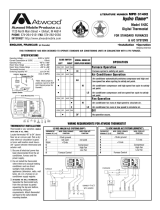
THIS THERMOSTAT HAS BEEN DESIGNED TO OPERATE STANDARD AIR CONDITIONING UNITS IN CONJUNCTION WITH A RV FURNACE
.
COOL FAN
OFF
HEAT
M
Display
System Switch
Temperature Set
Mode Set
7.5 VDC ANALOG A/C SYSTEMS (DOMETIC
®
)
THERMOSTAT WIRE FROM FURNACE WIRE FROM A/C
TERMINAL # (L-R)
FUNCTION FUNCTION
1-12vdc ground
4 7.5 vdc
3 +12vdc
5 Compressor
6 High Fan
7 Low Fan
8 Furnace Control
12 VDC ANALOG A/C SYSTEMS (RVP
®
)
THERMOSTAT WIRE FROM FURNACE WIRE FROM A/C
TERMINAL # (L-R)
FUNCTION FUNCTION
1 -12vdc ground
2 not used not used
3 & 4 +12vdc
5 Compressor
6 High Fan
7 Low Fan
8 Furnace Control
SLIDE SWITCH
SCROLL ORDER OF
LEFT RIGHT DISPLAYED MODES
OPERATION
COOL OFF HEAT FAN
Furnace Operation
• HI Furnace cycles to satisfy set point.
COOL OFF HEAT FAN
Air Conditioner Operation
•
AU
Air conditioner automatically switches compressor and high and
low speed fan when cycling to satisfy set point.
•
HI Air conditioner compressor and high speed fan cycle to satisfy
set point.
•
LO Air conditioner compressor and low speed fan cycle to satisfy
set point.
COOL OFF HEAT FAN
Fan Operation
•
HI Air conditioner fan runs at high speed to circulate air.
•
LO Air conditioner fan runs at low speed to circulate air.
COOL OFF HEAT FAN
Off
•
OF No operation occurs.
WIRING REQUIREMENTS FOR ATWOOD THERMOSTAT
FURNACE
12 VDC
SOURCE
+
7.5V
HI FAN
6
LOW FAN
7
COMPRESSOR
5
4
8
3
1
FURNACE
+
Y
GH GL B
HI FAN
6
LOW FAN
7
COMPRESSOR
5
12 VDC
SOURCE
8
3
1
CONNECT
4 TO 3
WITH JUMPER
1
12VDC
Ground
3
+12VDC
2
NOT
USED
Screw Mounting Holes
4
RELAY
COM
*
5
A/C
COM-
PRESSOR
6
A/C
HI
FAN
7
A/C
LOW
FAN
8
TH FROM
FURNACE
*
Note: Move jumper to
positions 3 and 4 for RVP
Unit. Discard jumper for
Dometic
®
.

1
12VDC
Ground
3
+12VDC
2
NOT
USED
Screw Mounting Holes
4
RELAY
COM
*
5
A/C
COM-
PRESSOR
6
A/C
HI
FAN
7
A/C
LOW
FAN
8
TH FROM
FURNACE
20
ENGLISH, FRANCAIS (et Canada) •Installation •Operation
Effective 9/21/04
LITERATURE NUMBER
MPD 31493
hydro flame
TM
Model 2H2C
Two Stage Furnace
Digital Thermostat
FOR TWO STAGE FURNACE
Specifications
Operating Voltage ...................... 9VDC to 18VDC
Power Consumption
................................ 100mA
Operating Temperature
.................. -40F to +185F
Room Temperature Range
.............. +55F to +90F
Room Temperature Display Range
.. +35F to +99F
Thermostat Accuracy
................................ +/- 1F
System Slide Switch
SCROLL ORDER OF
LEFT RIGHT DISPLAYED MODES
OPERATION
COOL OFF HEAT FAN
Scroll Order of Displayed Modes
Furnace Operation
•
AU Furnace automatically switches between high and low BTU valve and high
and low speed fan when cycling to satisfy set point.
•
HI Furnace high BTU valve and high speed furnace fan cycle to satisfy set point.
•
LO Furnace low BTU valve and low speed furnace fan cycle to satisfy set point.
•
HF Furnace fan runs at high speed to circulate air. Air conditioner fan does not run.
•
LF Furnace fan runs at low speed to circulate air. Air conditioner fan does not run.
COOL OFF HEAT FAN
Scroll Order of Displayed Modes
Air Conditioner Operation
•
AU
Air conditioner automatically switches compressor and high and low speed fan when
cycling to satisfy set point.
•
HI Air conditioner compressor and high speed fan operate to satisfy set point.
•
LO Air conditioner compressor and low speed fan operate to satisfy set point.
•
HF Air conditioner fan runs at high speed to circulate air. Furnace fan does not run.
•
LF Air conditioner fan runs at low speed to circulate air. Furnace fan does not run.
COOL OFF HEAT FAN
Scroll Order of Displayed Modes
Fan Operation
•
HI Air conditioner fan and furnace fan run at high speed to circulate air.
•
LO Air conditioner fan and furnace fan run at low speed to circulate air.
COOL OFF HEAT FAN
Scroll Order of Displayed Modes
Off
•
OF No operation occurs.
THERMOSTAT INSTALLATION
Thermostat is very sensitive. HANDLE WITH CARE AT ALL TIMES.
Locate thermostat 48˝ to 54˝ above floor on an INTERIOR wall.
Pick a dry area where air circulation is good. EXTERIOR wall
location must have a 3/4˝ spacer between thermostat and
exterior wall.
1. Be sure all electrical power has been disconnected from
the air conditioner, furnace and the power supply.
2. Do not install the thermostat where there are unusual
heating conditions: such as direct sunlight, heat
producing appliances (television, radio, wall lamp, etc.)
or a furnace or air conditioner supply register.
3.
ATTACHING THE WALL THERMOSTAT. Separate the thermostat
body from the sub-base by gently squeezing the top and
bottom. Pull wires through access hole in base plate.
Attach thermostat sub-base to the wall at the desired
mounting location. Mount the sub-base to the wall before
connecting the wires.
THIS THERMOSTAT HAS BEEN DESIGNED TO OPERATE STANDARD AIR CONDITIONING UNITS IN CONJUNCTION WITH AN EXCALIBUR 2-STAGE FURNACE.
*
Note: Move jumper to
positions 3 and 4 for RVP
Unit. Discard jumper for
Dometic
®
.
COOL FAN
OFF
HEAT
M
Display
System Switch
Temperature Set
Mode Set

21
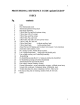
Anticipator setting
1.0
.20
.48 (valve
amperage)
WHAT IS A THERMOSTAT?
• It is an ON/OFF switch controlled by a bi-metal coil
which opens and closes an electrical contact by sensing
changes in the ambient temperature.
• With its contacts close, it supplies power to the time
delay relay which in turn closes a contact that sends
power to the blower motor.
• Normally, the thermostat contacts are closed if the
blower is running.
• The hydro flame thermostat is equipped with a heat
anticipator which allows one to adjust the length of the
heating cycles. A furnace should cycle 5-6 times an
hour.
a. The anticipator is set at 1.0 on all hydro flame
thermostats. If you want to shorten the heating
cycle, move anticipator to a lower amp setting. You
should not set lower than .48 which is the amperage
rating of the gas valve. Setting any lower could burn
out the anticipator wire.
Note: Heat anticipator adjustments are not covered under
warranty.
Mechanical Thermostat - HEAT ONLY
Heat/cool thermostats are being used in conjunction with air
conditioners and our furnace. The warranty, installation
instructions and diagnostic information is provided by the
manufacturer of the thermostat. However, if you need to
isolate a furnace problem or a dual thermostat problem, by-
pass the furnace wires at the thermostat. If the furnace
ignites and heats, you have a thermostat problem. If the
furnace does not run, the problem is in the furnace, and you
should consult the trouble shooting guides in the back of
this manual.
THERMOSTAT LOCATION
• It should be on an inside wall 48˝-54˝ above the floor on
an inside wall.
• It should not be near areas of extreme heat or cold.
• It should not be located directly across from a heat duct.
• If installed on an outside wall, a 3/4˝ spacer must be
used behind legs of thermostat. This will allow the
thermostat to sense the air temperature and not the
temperature of the wall.
• A minimum of 22 gauge wire should be used to connect
the thermostat to the furnace. We recommend
18 gauge stranded wire.
MOUNTING
HOLE
TEMPERATURE SETTING LEVEL
MOUNTING
HOLE
OFF LEVER
ANTICIPATOR
SETTING
LEVER
CAPPING
SCREWS
CAPPING
SCREWS
1
2
BASE FACE
BASE BACK

22
Guides are only intended for use on Atwood
®
products by service technicians who have successfully completed
Atwood
®
training. This guide should be used in conjunction with the appropriate Instruction Manual provided with the
product and any applicable Industry Standards. This is not intended to be a complete list. Please direct questions
concerning service of Atwood
®
products to 866-869-3118 option 5 before proceeding.
CAUSE SOLUTION
BLOWER DOES NOT RUN
Temperature selector out of place--------------------Re-set to desired position
Thermostat wires broken or disconnected ----------Not covered under warranty.
Heat anticipator burned out --------------------------Dead short (not covered under warranty). Repair short and then replace
thermostat.
Faulty relay drawing more than 1 amp. Replace relay and thermostat. Covered
under warranty.
No continuity through thermostat with
contacts closed and switch on. ----------------------Replace thermostat.
Continuity through thermostat with
contacts closed and switch on. ----------------------• Check and reestablish power to thermostat
• Reset tripped circuit breaker.
• Correct poor ground.
• Correct any loose wires.
• Replace defective relay.
• Replace defective motor.
FURNACE DOES NOT CYCLE PROPERLY
Furnace cycles too quickly ----------------------------Move anticipator to a higher amp setting to lengthen cycle. NOT covered
under warranty.
Thermostat located too close to a heat duct. Move thermostat or duct outlet.
NOT covered under warranty.
High temperature variance ----------------------------Move anticipator to a lower amp setting to shorten cycle. NOT covered under
warranty.
Note: When the anticipator is set properly and the heating system has operated for a few hours, the furnace should
cycle 5-6 time per hour.
hydro flame
Thermostat
TROUBLE SHOOTING GUIDE
Effective: 8/10/98
/