Page is loading ...

OPERATING
INSTRUCTIONS
Service Center &
Dealer Locations
Please Visit:
www.eDometic.com
Read these instructions carefully. These
instructions MUST stay with this product.
On/Off
Mode
Fan
Cool
Furnace
*Heat
Pump or
Heat Strip
˚C
SINGLE ZONE LCD THERMOSTAT
MODEL
3316154.000 COOL/FURNACE/HEAT PUMP
3316156.000 COOL/FURNACE/HEAT STRIP
Form No. 3316513.000 9/15
©2015 Dometic Corporation
LaGrange, IN 46761

2
TABLE OF CONTENTS
INTRODUCTION ........................................................................................................................................... 2
DOCUMENT SYMBOLS ...............................................................................................................................2
FAMILIARIZATION ........................................................................................................................................ 3
A. Features ....................................................................................................................................3
B. System Initialization ................................................................................................................... 3
C. Factory Preset Settings .............................................................................................................3
D. Quick Reference ........................................................................................................................ 3
PROGRAMMING AND OPERATION ............................................................................................................4
A. On/Off ........................................................................................................................................4
B. Temperature Format ºC / ºF .......................................................................................................4
C. Inside Temperature .................................................................................................................... 5
D. Mode Selection .......................................................................................................................... 5
E. Fan Speed ................................................................................................................................. 6
F. Temperature Set-Point ...............................................................................................................6
MODE DESCRIPTION ..................................................................................................................................7
A. “Off” - Off Mode..........................................................................................................................7
B. “Cool” - Cool Mode ....................................................................................................................7
C. “Furnace” - Furnace Mode .........................................................................................................7
D. “Heat Pump” - Heat Pump Mode (Select Models) ..................................................................... 7
E. “Heat Strip” - Heat Strip Mode (Select Models) ......................................................................... 8
F. “Fan” - Fan Mode .......................................................................................................................8
SPECIAL FEATURES....................................................................................................................................8
A. Auto Fan .................................................................................................................................... 8
B. Compressor Time Delay ............................................................................................................ 8
C. Defrost Cycle ............................................................................................................................. 9
D. Low Ambient Heat Pump Lock Out ............................................................................................9
E. Power Interruption .....................................................................................................................9
F. LCD Error Code ......................................................................................................................... 9
GENERAL INFORMATION ..........................................................................................................................10
A. Frost Formation On Cooling Coil ............................................................................................. 10
B. Heat Gain ................................................................................................................................10
C. Condensation ..........................................................................................................................10
MAINTENANCE .......................................................................................................................................... 11
A. Air Filter ................................................................................................................................... 11
B. SZ LCD Thermostat ................................................................................................................. 11
SERVICE - UNIT DOES NOT OPERATE .................................................................................................... 11
INTRODUCTION
This Single Zone LCD thermostat (hereinafter referred to as “SZ LCD thermostat” or “product”) is designed
and intended for use in a Recreational Vehicle (hereinafter referred to as RV). Use these instructions to
ensure correct installation, function, and operation of product.
Dometic Corporation reserves the right to modify appearances and specications without notice.
DOCUMENT SYMBOLS
Indicates additional information that is NOT
related to physical injury.
Indicates step-by-step instructions.

33
To familiarize yourself with operation of your new SZ LCD thermostat, review the following dia-
grams and accompanying text explaining functional characteristics of this system.
A. Features
● Liquid Crystal Display (LCD)
● Green LED Mode Indicators
● Auto Fan
● Indoor Temperature Display
● Air conditioner can provide additional indoor air circulation during furnace operation.
B. System Initialization
A system initialization will need to be performed by installer after system installation.
1. Make sure SZ LCD thermostat is Off. See
2. Press the + button, and simultaneously press and hold the On/Off Mode button for three
seconds. LCD will show “- -”.
3. Press the On/Off Mode button again to turn system off.
This completes system initialization.
Furnace On/Off temperature differential should be set at this time. See “C. “Furnace” - Fur-
nace Mode” on page (7).
C. Factory Preset Settings
SZ LCD thermostat is pre-programmed. Review settings below and adjust for personal comfort
level.
Factory Preset Settings
Heating 20ºC / 68ºF
Cooling 22ºC / 72ºF
Fan Speed Auto
Mode Off
Furnace Differential 2ºF
D. Quick Reference
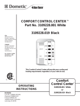
See (FIG. 1) for control button quick reference.
FAMILIARIZATION

4
On/Off
Mode
Fan
Cool
Furnace
*Heat
Pump or
Heat Strip
˚C
FIG. 1
*Select Models
LED
Indicators
Indicates
Mode Of
Operation
When
Illuminated
Press To
Increase
Temperature
Set-Point
Press To
Select
Mode Of
Operation
Press To
Increase
Temperature
Set-Point
FAMILIARIZATION
PROGRAMMING AND OPERATION
A. On/Off
1. To turn On the SZ LCD thermostat, press On/Off Mode button. To turn Off the SZ LCD ther-
mostat press the On/Off Mode button and toggle through modes until On/Off green LED is on.
LCD will go out while the green LED will remain on for approximately 15 seconds, then go out.
B. Temperature Format ºC / ºF
1. Simultaneously press the + and - buttons to toggle between Centigrade and Fahrenheit for-
mat. ºC indicates Centigrade and ºF indicates Fahrenheit. See (FIG. 2).
On/Off
Mode
Fan
Cool
Furnace
*Heat
Pump or
Heat Strip
˚C
FIG. 2
Temperature
Format
*Select Models

5
C. Inside Temperature
1. To display the Inside Temperature, SZ LCD thermostat must be in Off Mode. Press either +
or - button to display the Inside Temperature. See (FIG. 3).
On/Off
Mode
Fan
Cool
Furnace
˚F
˚C
FIG. 3
Inside
Temperature
D. Mode Selection
1. Press On/Off Mode button to advance through available modes. Each successive press will
advance to next available mode. The green LED will indicate mode selected. See (FIG. 4).
Dependent upon systems installed, options will be Off, Fan, Cool, Furnace, Heat Pump, or
Heat Strip. See “Mode Description” on page (7) for more information.
On/Off
Mode
Fan
Cool
Furnace
˚F
˚C
FIG. 4
PROGRAMMING AND OPERATION

6
PROGRAMMING AND OPERATION
E. Fan Speed
1. Press On/Off Mode button until Fan green LED illuminates. See (FIG. 5)The LCD will show
“Lo” (Low), “Hi” (High), or “Au” (Auto). Press the + or - button to select desired fan speed. See
“A. Auto Fan” on page (8) for more information.
On/Off
Mode
Fan
Cool
Furnace
FIG. 5
Fan Speed
F. Temperature Set-Point
1. Press On/Off Mode button to change temperature set-point. Temperature set-point is indi-
cated by two digits on LCD. Press + to increase or - to decrease temperature. The maximum
set-point for the system is 32ºC. The minimum set point is determined by active operating
mode. For heating, the minimum is 4ºC and minimum for cooling is 13ºC. See (FIG. 6).
On/Off
Mode
Fan
Cool
Furnace
˚F
˚C
FIG. 6
Temperature
Set-Point

7
MODE DESCRIPTION
A. “Off” - Off Mode
1. When selected, LCD will be blank and the Off green LED will turn on for 15 seconds, then
turn off.
B. “Cool” - Cool Mode
1. In Cool Mode, system will cycle compressor On and Off based on room air temperature and
temperature set-point on SZ LCD thermostat. Fan will turn on rst, followed by the compres-
sor approximately 2 minutes later. There are 3 fan speeds in Cool Mode.
a. “Lo” (Low): Fan operates continuously at low speed. The compressor cycles On and
Off.
b. “Hi” (High): Fan operates continuously at high speed. The compressor cycles On and
Off.
c. “Au” (Auto): Fan speed will vary depending on difference between the temperature set-
point and room air temperature. The compressor and the fan will cycle On and Off with
thermostat. See “A. Auto Fan” on page (8) for more information.
C. “Furnace” - Furnace Mode
1. There are 3 fan speeds in Furnace Mode.
a. “Lo” (Low): Fan operates continuously at low speed.
b. “Hi” (High): Fan operates continuously at high speed.
c. “Au” (Auto): Fan is Off.
If additional indoor air circulation provided by the air conditioner is NOT desired during
Furnace Mode of operation, select Au (Auto) in the Fan Mode to shut the air conditioner
fan off. If “Lo” (Low) or “Hi” (High) is selected, the air conditioner fan will continue to
operate at selected speed.
2. In Furnace Mode system will cycle RV furnace On and Off based on room air temperature
and temperature set-point on SZ LCD thermostat. SZ LCD thermostat can be congured to
operate using an On/Off differential of either 1ºF or 2ºF. This feature is programmed during the
system initialization. See “B. System Initialization” on page (3).
3. To set temperature differential, system must be Off. Press - button and simultaneously press
and hold On/Off Mode button for three seconds. Press + button to toggle between “d1” and
“d2”, “d1” for 1ºF differential and “d2” for 2ºF differential.
D. “Heat Pump” - Heat Pump Mode (Select Models)
1. In Heat Pump Mode, system will cycle compressor On and Off based on room air temperature
and temperature set-point on SZ LCD thermostat. When system calls for heating there will be
a delay of approximately 2 minutes. There are 3 fan speeds in Heat Pump Mode.
a. “Lo” (Low): Fan operates continuously at low speed. The compressor cycles On and
Off.
b. “Hi” (High): Fan operates continuously at high speed. The compressor cycles On and
Off.

8
MODE DESCRIPTION
c. “Au” (Auto): Fan speed will vary depending on difference between the temperature set-
point and room air temperature. The compressor and the fan will cycle On and Off with
thermostat. Compressor shuts off rst followed by fan in approximately 15 seconds. See
“A. Auto Fan” on page (8) for more information.
2. This mode of operation is a customer option usually selected when temperatures are below
21ºC and customer needs warmth in living space rather than cool down. This reverses refrig-
erant ow in the air conditioner, causing warm air to be dispensed inside rather than cold, and
cold air is dispensed outside rather than warm.
3. This mode of operation can cause a dilemma where the outside coil, which is now dispensing
cold air can freeze up due to cold air blowing across the coil mixed with outside temperature. A
system freeze up can render heat pump inoperable. There is a defrost feature that will prevent
this from happening. See “C. Defrost Cycle” on page (9) for more information.
E. “Heat Strip” - Heat Strip Mode (Select Models)
1. In Heat Strip Mode, system will cycle heat strip On and Off based on room air temperature
and temperature set-point on SZ LCD thermostat. There are 3 fan speeds in Heat Strip Mode.
a. “Lo” (Low): Fan operates continuously at low speed. Heat strip cycles On and Off.
b. “Hi” (High): Fan operates continuously at high speed. Heat strip cycles On and Off.
c. “Au” (Auto): Fan operates in low speed and will cycle On and Off with thermostat.
F. “Fan” - Fan Mode
1. There are 3 fan speeds in Fan mode.
a. “Lo” (Low): Fan operates continuously at low speed.
b. “Hi” (High): Fan operates continuously at high speed.
c. “Au” (Auto): Fan is Off.
SPECIAL FEATURES
A. Auto Fan
When auto fan is selected fan speed will vary depending on room temperature and temperature
set-point. In auto fan compressor and fan cycle On and Off with thermostat.
When difference is:
> 3ºC Fan operates on HIGH
< 2ºC Fan operates on LOW
B. Compressor Time Delay
A time delay of approximately 2 minutes occurs anytime compressor is required to begin cooling
or heat pump cycle.

9
SPECIAL FEATURES
C. Defrost Cycle
During heat pump operation, if outside coil begins to freeze up, a defrost cycle is initiated that
temporarily puts heat pump back into air conditioning mode. This reverses the refrigerant ow
and melts ice forming on outside coil. Typically this occurs when outside temperatures are below
6ºC and repeats every 25 minutes of compressor run time. During this period operation the user
will temporarily feel cold air inside RV from registers. This is normal and is NOT and indication of
malfunction.
Defrost cycling SHALL continue until measured temperature of Outside Sensor is < -1ºC
or > 6ºC.
D. Low Ambient Heat Pump Lock Out
All heat pumps are constrained to operation at a temperature range determined by outside condi-
tions. Since all heat pumps lose efciency at low outside ambient temperatures, the heat pump
has a lock out feature that prevents heat pump mode of operation when temperatures fall below
-1ºC. If system is set in Auto Mode fan will be turned OFF. Fan will remain ON if fan setting is set
to Low or High, however compressor will not run and there will be no heat function below -1ºC.
E. Power Interruption
In the event power to air conditioner or control is interrupted, system will restart with previous set-
points once power is restored.
F. LCD Error Code
When system determines one of the faults listed has occurred, an error code will be displayed
on LCD.
Error Code:
E1 Loss of communication between SZ LCD thermostat and module board. LCD will cycle
between E1 and previous mode setting. System will shut down.
E2 Open circuit or out of range Indoor Temperature Sensor. Heating and cooling operation
will be locked out. Fan operation can continue to operate.
E3 Shorted Indoor Temperature Sensor. Heating and cooling operation will be locked out.
Fan operation can continue to operate.
E4 Open circuit or out of range Outdoor Temperature Sensor (select models). Heat Pump
operation will be locked out. Air Conditioner, Fan, and Furnace operation can continue to
operate.
E5 Open Circuit or out of range Freeze Sensor. Air Conditioner mode of operation can con-
tinue, but displays the last temperature set-point.

10
GENERAL INFORMATION
A. Frost Formation On Cooling Coil
1. Frost on a small portion of the coil is not unusual. Under certain conditions, ice may form on
the evaporator coil. This is indicated by very cold output at very low air speed and the icing
can be seen through the air inlet hole with the lter removed. If this should occur, inspect the
lter and clean if dirty. Make sure air vents are open and not obstructed. Units have a greater
tendency to frost when the outside temperature is relatively low. This may be prevented by
adjusting the thermostat control knob to a warmer setting (counter clockwise). Should frosting
continue, operate on any FAN ONLY setting until the cooling coil is free of frost; then resume
normal operation. If frost condition persist, contact your local service center for assistance.
B. Heat Gain
The ability of this air conditioner to maintain the desired inside temperature depends on the heat gain of the RV.
Some preventative measures taken by the occupants of the RV can reduce the heat gain and improve the
performance of the air conditioner. During extremely high outdoor temperatures, the heat gain of the RV
may be reduced by:
1. Parking the RV in a shaded area
2. Using window shades (blinds and/or curtains)
3. Keeping windows and doors shut or minimizing usage
4. Avoiding the use of heat producing appliances
Operation on High Fan/Cooling mode will give optimum or maximum efciency in high humidity or high
outside temperatures.
Starting the air conditioner early in the morning and giving it a “head start” on the expected high outdoor
ambient will greatly improve its ability to maintain the desired indoor temperature.
For a more permanent solution to high heat gain, accessories like Dometic outdoor patio and window aw-
nings will reduce heat gain by removing the direct sun. They also add a nice area to enjoy company during
the cool of the evening.
C. Condensation
The manufacturer of this unit will not be responsible for damage caused by condensation forming on ceilings,
windows, or other surfaces. Air contains water vapor which condenses when temperature of a surface is
below Dew point. During normal operation this unit is designed to remove a certain amount of moisture from
the air, depending on the size of the space being conditioned. Keeping doors and windows closed when this
air conditioner is in operation will greatly reduce the chance of condensation forming on interior surfaces.

11
MAINTENANCE
A. Air Filter
1. Periodically (a minimum of every 2 weeks of operation) remove the return air lter located be-
hind the return air vent grille and wash it with soap and warm water, let dry and then reinstall.
NEVER run unit without return air lter in place. This will plug the unit evaporator
coil with dirt and may substantially degrade the performance of the unit over time.
B. SZ LCD Thermostat
1. Clean SZ LCD thermostat with a moist soft cloth.
DO NOT spray water directly on SZ LCD thermostat. DO NOT use solvents for
cleaning.
SERVICE - UNIT DOES NOT OPERATE
If your unit fails to operate or operates improperly, check the following before calling your service center.
● If RV connected to motor generator, check to be sure motor generator is running and pro-
ducing power.
● If RV connected to power supply by a land line, check to be sure line is sized properly to run
unit load and it is plugged into power supply.
● Check your fuse or circuit breaker to see if it is open. Insure fuse is not burnt, or circuit
breaker is “ON” and not activated.
● After the above checks, call your local service center for further help. This unit must be
serviced by qualied service personnel only.
When calling for service, always give the following:
● Unit model and serial number found on the identication label located on base pan of unit
bottom. Return air vent grille must be removed from ADB to view.
● ADB model and serial number found on rating plate located on ceiling template. Observe
this rating plate through the lter opening.
/