3M Cold Shrink QT-III 3/C Termination Kit 7695-S-4-3W, Tape/Wire/UniShield®, 5-25/28 kV, Insulation OD 1.18-1.52 in, 3/kit Operating instructions
- Type
- Operating instructions
This manual is also suitable for
- Cold Shrink QT-III 3/C Termination Kit 7620-S-2-3W, Tape/Wire/UniShield®, 5-8.7 kV, Insulation OD 0.33-0.50 in, 3/kit
- Cold Shrink QT-III 3/C Termination Kit 7621-S-2-3W, Tape/Wire/UniShield®, 5-15 kV, Insulation OD 0.50-0.70 in, 3/kit
- Cold Shrink QT-III 3/C Termination Kit 7622-S-2-3W, Tape/Wire/UniShield®, 5-15 kV, Insulation OD 0.70-0.92 in, 3/kit
- Cold Shrink QT-III 3/C Termination Kit 7685-S-8-3W, Tape/Wire/UniShield®, 5-35 kV, Insulation OD 1.18-1.52 in, 3/kit
- Cold Shrink QT-III 3/C Termination Kit 7691-S-4-3W, Tape/Wire/UniShield®, 5-15 kV, Insulation OD 0.50-0.70 in, 3/kit
- Cold Shrink QT-III 3/C Termination Kit 7692-S-4-3W, Tape/Wire/UniShield®, 5-25/28 kV, Insulation OD 0.70-0.92 in, 3/kit
- Cold Shrink QT-III 3/C Termination Kit 7693-S-4-3W, Tape/Wire/UniShield®, 5-25/28 kV, Insulation OD 0.92-1.18 in, 3/kit

3M
™
Cold Shrink Silicone Rubber
Outdoor Termination Kit QT-III
7600-S-3W Series
For 3-Conductor Copper Tape Shield Cables
without Ground Wires
Instructions
IEEE Std. No. 48
Class 1 Termination
CAUTION
Working around energized electrical systems may cause serious injury or death. Installation should
be performed by personnel familiar with good safety practice in handling electrical equipment.
De-energize and ground all electrical systems before installing product.
September 2008
78-8127-6974-9

2 78-8127-6974-9
Kit Contents
1 Cold Shrink Silicone Rubber Breakout Boot Assembly
3 Silicone Rubber Phase Re-jacketing Sleeve Assembly
3 Cold Shrink Silicone Rubber Termination Assembly
1 Roll Tinned Copper Ground Braid
3 Constant-Force Spring (Small)
1 Constant-Force Spring (Large)
3 Copper Foil Tape, 1/2" x 10"
2 Mastic Seal Strips
1 Roll Vinyl Tape
1 Cable Preparation Kit
1 Installation Instructions
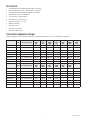
Termination Application Ranges
(Final determining factor is cable insulation diameter. Listed insulation ranges allow +2.54 mm (0.10") for shielding.)
Kit Number BIL
(kV)
Cable Insulation
Range [inch (mm)]
3.3 kV
(mm
2
)
IEC
3.3 kV
(mm
2
)
JIS
5.0 kV
(AWG)
AEIC
6.6 kV
(mm
2
)
JIS
6.6 kV
(mm
2
)
IEC
8.7 kV
(AWG)
AEIC
10 kV
(mm
2
)
IEC
7620-S2-3W 95 8.40–12.7 (0.33–0.50) 16–35 8–22 8–2 — 16–25 6–4 —
7621-S2-3W 95 12.7–17.8 (0.50–0.70) 50–95 38–60 1–3/0 — 35–70 2–2/0 10–50
7622-S2-3W 110 17.8–23.4 (0.70–0.92) 120–185 100–150 4/0–400 60–100 95–150 3/0–350 70–150
7691-S4-3W 150 12.7–17.8 (0.50–0.70) 50–95 38–60 1–3/0 — 35–70 2–2/0 10–50
7692-S4-3W 150 17.8–23.4 (0.70–0.92) 120–185 100–150 4/0–400 60–100 95–150 3/0–350 70–150
7693-S4-3W 150 23.4–30.0 (0.92–1.18) 240–300 200–250 500–750 150–250 185–300 400–600 185–300
7695-S4-3W 150 30.0–38.6 (1.18–1.52) — 300–325 800–1000 300–325 — 750–1000 —
7685-S8-3W 200 30.0–38.6 (1.18–1.52) — 300–325 800–1000 300–325 — 750–1000 —
Kit Number BIL
(kV)
Cable Insulation
Range [inch (mm)]
15 kV
(mm
2
)
IEC
15 kV
(AWG)
AEIC
20 kV
(mm
2
)
IEC
25/28 kV
(AWG)
AEIC
30 kV
(mm
2
)
IEC
35 kV
(AWG)
AEIC
7620-S2-3W 95 8.40–12.7 (0.33–0.50) — — — — — —
7621-S2-3W 95 12.7–17.8 (0.50–0.70) 16–25 — — — — —
7622-S2-3W 110 17.8–23.4 (0.70–0.92) 35–95 1/0–4/0 — — — —
7691-S4-3W 150 12.7–17.8 (0.50–0.70) 16–25 — — — — —
7692-S4-3W 150 17.8–23.4 (0.70–0.92) 35–95 1/0–4/0 25–70 2–1/0 — —
7693-S4-3W 150 23.4–30.0 (0.92–1.18) 120–185 250–450 95–185 2/0–250 — —
7695-S4-3W 150 30.0–38.6 (1.18–1.52) 200–325 500–750 240–300 300–500 — —
7685-S8-3W 200 30.0–38.6 (1.18–1.52) 200–325 500–750 240–300 300–500 95–240 4/0–500
Table 1

78-8127-6974-9 3
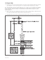
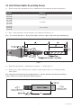
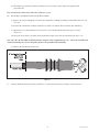
Prepare Cable1.0
Determine cable jacket removal length required for correct phase spacing and bolted terminal lug connections 1.1
([A] + [B] Figure 1, based on the longest phase to be connected). Allow for dimension [C] as needed.
Note: Individual phase length and separation dimensions vary according to specific installation and equipment
design requirements. They must, therefore, be determined by the installer and must conform to accepted
engineering practices.
Remove cable jacket, armor, bedding (inner sheath) and core fillers according to Figure 1 dimensions. Secure 1.2
each copper tape shield end with a temporary band of vinyl tape (
①
Figure 1).
Using light tension, wrap a mastic seal strip around cable jacket 25 mm (1.0") below the cut edge (1.3
②
Figure 1).
Figure 1

4 78-8127-6974-9
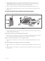
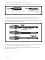
Attach Metallic Shield Grounding Braids2.0
Cut supplied tinned copper grounding braid into three equal 2' (610 mm) lengths. Expand each braid end for a 2.1
distance of 12" (300 mm) (
②
Figure 2).
12" (300 mm)
Figure 2
Position each expanded ground braid end over cable as shown in Figure 3. Using vinyl tape bands, secure upper 2.2
braid end to copper tape shielding 200 mm (8.0") beyond armor edge (jacket edge for non-armored cable)
(➃ Figure 3). Secure to cable jacket 15 mm (0.60") below mastic seal strip (➄ Figure 3).
Figure 3

78-8127-6974-9 5
Connect ground braid upper ends to copper tape shield using small constant force spring (2.3 ➅ Figure 3).
Armored cables: Connect three ground braids to cable armoring using one large constant force spring
(➆ Figure 3). Following application, cinch (twist with hand) each spring to tighten.
Apply a second mastic seal strip over ground braids and previously-applied mastic strip (2.4 ⑧ Figure 3).
Apply two highly stretched half-lapped layers vinyl tape over mastic seal strips and constant force springs 2.5
(⑨ Figure 3).
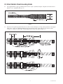
Install Cold Shrink Silicone Rubber Breakout Boot Assembly3.0
Inspect boot assembly and confirm that all loose plastic core ends are free as shown (3.1 ① and ② Figure 4).
Figure 4
To ensure that the breakout boot can be fully seated into the breakout area of the cable, it will be necessary to 3.2
unwind a few turns of each finger core.
Caution: Do not unwind too far such that boot fingers begin to collapse.
Hold loose neck-end core ribbon 3.3 ② to one side so that it can not become trapped between cable phases. Slide
boot assembly over cable end, guiding individual cable cores through boot assembly fingers.
Hint: View end of cable through finger cores to ease cable phase insertion.
Slide breakout boot assembly onto cable as far as it will go. Large neck-end should fully extend over cable 3.4
jacket.
Hint: Spread cable phases while sliding boot assembly to ease the installation.
Remove large neck-end core. Grasping loose core ribbon end 3.5 ②, pull and unwind counter clock-wise around
cable.
Remove each finger core. Grasping loose core ribbon end 3.6 ①, pull and unwind counter clock-wise around each
cable phase leg.

6 78-8127-6974-9
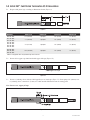
Install Silicone Rubber Re-jacketing Sleeves4.0
From the chart below, determine the correct A dimension for the termination product being installed.4.1
Kit Number Dimension A
7620-S2-3W 6 3/4" (171 mm)
7621-S2-3W
7622-S2-3W
7" (178 mm)
7691-S4-3W
7692-S4-3W
7693-S4-3W
7695-S4-3W
9" (229 mm)
7684-S8-3W
7685-S8-3W
7686-S8-3W
16 1/4" (413 mm)
Place a vinyl tape marker on each cable phase leg at dimension X (4.2
①
Figure 5).
Note: X = A (From chart above) + B (Lug barrel depth). Allow for crimp growth when using aluminum lugs.
Figure 5
Determine required phase re-jacketing sleeve length (S - 1" (25 mm) 4.3 Figure 5).
Using scissors, trim re-jacketing sleeve assembly to length required (4.4 Figure 6). Cut tubing and inner
braid together.
Note: Inner polyester braid should extend approximately 3" (75 mm) beyond re-jacketing tube end before
cutting. There is no need for termination-end braid exposure.
Figure 6

78-8127-6974-9 7
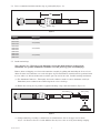
Guide one re-jacketing sleeve assembly over each cable phase leg (4.5 Figure 7).
Push sleeve assembly from above. Continuously guide the free end maintaining sleeve-to-cable-core alignment.
Figure 7
Slide re-jacketing sleeve until inner polyester braid is adjacent to breakout boot finger (4.6 ② Figure 8).
Fold outer silicone tubing back on itself for 1" (25 mm) and trim off exposed polyester braid (4.7 ③ Figure 8).
Note: Do not damage silicone tubing while cutting. Sleeve assembly may be rotated to ease trimming. When doing
so, rotate in the direction of the cable copper tape shield wrap.
Figure 8
Slide re-jacketing sleeve assembly down until folded tube contacts edge of breakout boot finger (4.8 ➃ Figure 8).
Pull folded silicone tube section down onto breakout boot finger (4.9 ➄ Figure 8).
Note: Re-jacketing tube end should align with upper edge of installed marker tape (➅ Figure 8). Minor tube
adjustments can be made as needed.

8 78-8127-6974-9
Install 3M5.0
™
Cold Shrink Termination QT-III Assemblies
Prepare cable phase legs according to dimensions shown (5.1 Figure 9).
Figure 9
Kit Number Dimension A Dimension B Dimension C Dimension D
7620-S2-3RJS 6.7" (170 mm) Lug Depth* 2.0" (51 mm) 1.2" (30 mm)
7621-S2-3RJS
7622-S2-3RJS
7.1" (180 mm) Lug Depth* 3.0" (76 mm) 1.2" (30 mm)
7691-S4-3RJS
7692-S4-3RJS
7693-S4-3RJS
7695-S4-3RJS
9.1" (231 mm) Lug Depth* 3.0" (76 mm) 1.2" (30 mm)
7684-S8-3RJS
7685-S8-3RJS
7686-S8-3RJS
16.3" (414 mm) Lug Depth* 3.0" (76 mm) 1.2" (30 mm)
*Allow for crimp growth when using aluminum lugs and connectors.
Secure cable copper tape shield ends with copper foil tape (5.2 Figure 10).
Copper Foil Tape
Figure 10
Secure re-jacketing sleeve with two half-lapped layers of vinyl tape (5.3 Figure 11). Start taping 0.8" (20 mm) over
re-jacketing sleeve, extend 0.2" (5 mm) over cable metallic shield and return to starting point.
Note: Do not cover copper foil tape.
Figure 11

78-8127-6974-9 9
Place a termination installation marker tape at position [M] (5.4 Figure 12).
[M]
Marker Tape
Figure 12
Kit Number Dimension M
7620-S2-3G 3.0" (76 mm)
7621-S2-3G
7622-S2-3G
4.9" (125 mm)
7691-S4-3G
7692-S4-3G
7693-S4-3G
7695-S4-3G
4.9" (125 mm)
7684-S8-3G
7685-S8-3G
7686-S8-3G
4.9" (125 mm)
Install terminal lugs.5.5
Note: Special Case – When lug spade dimension is larger than inside diameter of white plastic
termination core, position termination assemblies over cable phase legs prior to installing lugs.
Remove inner red shipping core from each termination assembly by pulling and unwinding the loose red core
ribbon. Position one termination over each cable phase leg. Each termination assembly must be positioned with
its loose white core ribbon end directed toward the open (cut) end of the cable. Continue with lug installations.
(a.) For Aluminum Conductors - Thoroughly wire brush conductor strands to remove aluminum oxide layer.
Immediately insert conductor into terminal lug barrel as far as it will go.
(b.) Ensure that each lug face is parallel to equipment bushing or lug connection interface (Figure 13).
Last Crimp
First Crimp
Figure 13
(c.) Crimp terminal lug according to manufacturer recommendations. Start at the upper end as shown
(Figure 13). Remove all traces of oxide inhibitor that may have come out of lug barrel during crimping.

10 78-8127-6974-9
(d.) Thoroughly clean primary insulation and lug barrel area using solvent wipe from supplied cable
preparation kit.
Note: Avoid solvent contact with cable semi-conductive screen.
Install 3M5.6
™
Cold Shrink Termination QT-III assemblies.
(a.) Remove the inner red shipping core from the termination assembly by pulling and unwinding the loose red
core end.
(b.) Position the termination assembly with the loose white core ribbon directed toward the terminal lug.
(c.) Align the base of the termination (not the plastic core) with the installation marker tape as shown
(Figure 14).
(d.) Grasp the loose white core ribbon. Pull and unwind counter clock-wise around cable end (Figure 14).
Note: After the silicone rubber termination makes adequate contact (approximately 1.0”), release the assembly and
continue unwinding the core. Do not pull or push on the assembly while unwinding.
(e.) Remove the installation marker tape.
Figure 14
Connect shield braid tails and cable ground wire to system ground (earth) according to normal practice.5.7

78-8127-6974-9 11

3M is a trademark of 3M Company.
Important Notice
All statements, technical information, and recommendations related to 3M's products are based on information believed to be reliable,
but the accuracy or completeness is not guaranteed.
Before using this product, you must evaluate it and determine if it is suitable for
your intended application.
You assume all risks and liability associated with such use.
Any statements related to the product which are not
contained in 3M's current publications, or any contrary statements contained on your purchase order shall have no force or effect unless
expressly agreed upon, in writing, by an authorized officer of 3M.
Warranty; Limited Remedy; Limited Liability.
This product will be free from defects in material and manufacture at the time of purchase.
3M MAKES NO OTHER WARRANTIES
INCLUDING, BUT NOT LIMITED TO, ANY IMPLIED WARRANTY OF MERCHANTABILITY OR FITNESS FOR A PARTICULAR PURPOSE.
If this product is defective within the warranty period stated above, your exclusive remedy shall be, at 3M's option, to replace or repair the
3M product or refund the purchase price of the 3M product.
Except where prohibited by law, 3M will not be liable for any indirect,
special, incidental or consequential loss or damage arising from this 3M product, regardless of the legal theory asserted.
3
Electrical Markets Division
6801 River Place Blvd.
Austin, TX 78726-9000
800-245-3573
Fax 800-245-0329
www.3M.com/electrical
Please Recycle. Printed in USA.
© 3M 2008. All Rights Reserved.
78-8127-6974-9
-
 1
1
-
 2
2
-
 3
3
-
 4
4
-
 5
5
-
 6
6
-
 7
7
-
 8
8
-
 9
9
-
 10
10
-
 11
11
-
 12
12


3M Cold Shrink QT-III 3/C Termination Kit 7695-S-4-3W, Tape/Wire/UniShield®, 5-25/28 kV, Insulation OD 1.18-1.52 in, 3/kit Operating instructions
- Type
- Operating instructions
- This manual is also suitable for
-
- Cold Shrink QT-III 3/C Termination Kit 7620-S-2-3W, Tape/Wire/UniShield®, 5-8.7 kV, Insulation OD 0.33-0.50 in, 3/kit
- Cold Shrink QT-III 3/C Termination Kit 7621-S-2-3W, Tape/Wire/UniShield®, 5-15 kV, Insulation OD 0.50-0.70 in, 3/kit
- Cold Shrink QT-III 3/C Termination Kit 7622-S-2-3W, Tape/Wire/UniShield®, 5-15 kV, Insulation OD 0.70-0.92 in, 3/kit
- Cold Shrink QT-III 3/C Termination Kit 7685-S-8-3W, Tape/Wire/UniShield®, 5-35 kV, Insulation OD 1.18-1.52 in, 3/kit
- Cold Shrink QT-III 3/C Termination Kit 7691-S-4-3W, Tape/Wire/UniShield®, 5-15 kV, Insulation OD 0.50-0.70 in, 3/kit
- Cold Shrink QT-III 3/C Termination Kit 7692-S-4-3W, Tape/Wire/UniShield®, 5-25/28 kV, Insulation OD 0.70-0.92 in, 3/kit
- Cold Shrink QT-III 3/C Termination Kit 7693-S-4-3W, Tape/Wire/UniShield®, 5-25/28 kV, Insulation OD 0.92-1.18 in, 3/kit
Ask a question and I''ll find the answer in the document
Finding information in a document is now easier with AI
Related papers
-
3M Cold Shrink Quick Splice Low Voltage QSLV-M 8-2/0, Non-shielded, 1 kV, 10/case Operating instructions
-
-
-
-
-
3M Cold Shrink QT-III 3/C Termination Kit 7684-S-8-3G, Tape/Wire/UniShield®, 15-35 kV, Insulation OD 0.92-1.18 in, 3/kit Operating instructions
-
-
-
3M Cold Shrink QT-III 3/C Termination Kit 7693-T-150-3G, Tape/Wire/UniShield®, 5-25 kV, Insulation OD 0.70-0.92 in, 3/kit Operating instructions
-
Other documents
-
 DIODE LED 12mm Tape Light Terminal Block Connector Installation guide
-
Chromalox RG-PK Installation guide
-
DEVI 98805021 Operating instructions
-
A D AD-8127 User manual
-
-
Extreme Networks AP7622 Installation guide
-
-
 Nexans 33kV CWS Installation guide
-
 Tyco Electronics Raychem HVS-T-1580E-S Series User manual


