3M Cold Shrink QT-III 3/C Termination Kit 7693-T-150-3G, Tape/Wire/UniShield®, 5-25 kV, Insulation OD 0.70-0.92 in, 3/kit Operating instructions

Type
Operating instructions
3M
Cold Shrink QT-III Silicone
Rubber Indoor Termination Kits
With High-K Stress Relief
For 3-Conductor Type “G” (Ground Wire) Copper Tape
Shield and Armored Cables
7600-T-3G Series
Instructions
IEEE Std. No. 48
Class 1 Termination
F CAUTION
Working around energized systems may cause serious injury or death. Installation should
be performed by personnel familiar with good safety practice in handling electrical
equipment. De-energize and ground all electrical systems before installing product.
August 2013
78-8127-6976-4 Rev D 3
2 78-8127-6976-4 Rev D
Kit Contents
1 Cold Shrink Silicone Rubber Breakout Boot Assembly
1 Cold Shrink Silicone Rubber Jacket Seal Assembly
3 Silicone Rubber Phase Rejacketing Sleeve Assemblies
3 Cold Shrink Silicone Rubber Termination Assemblies
1 Tinned Copper Ground Braid Assembly
3 Constant-Force Springs (Small)
1 Constant-Force Spring (Large)
8 Strips Scotch®
Mastic Strip 2230 (2 per termination bag & 2 per breakout boot bag)
1 Roll Scotch® Super 33+™ Vinyl Electrical Tape - 3/4"
1 Roll Scotch® Vinyl Electrical Tape Super 88 - 1-1/2"
1 Roll Scotch®
Electrical Shielding Tape 24
1 3M™ Cable Cleaning Preparation Kit CC-2
1 Instruction Sheet
3 3M™
EMI Copper Foil Shielding Tape 1181 Strips, 1/2" x 10"
NOTE: Do Not use knives to open plastic bags.
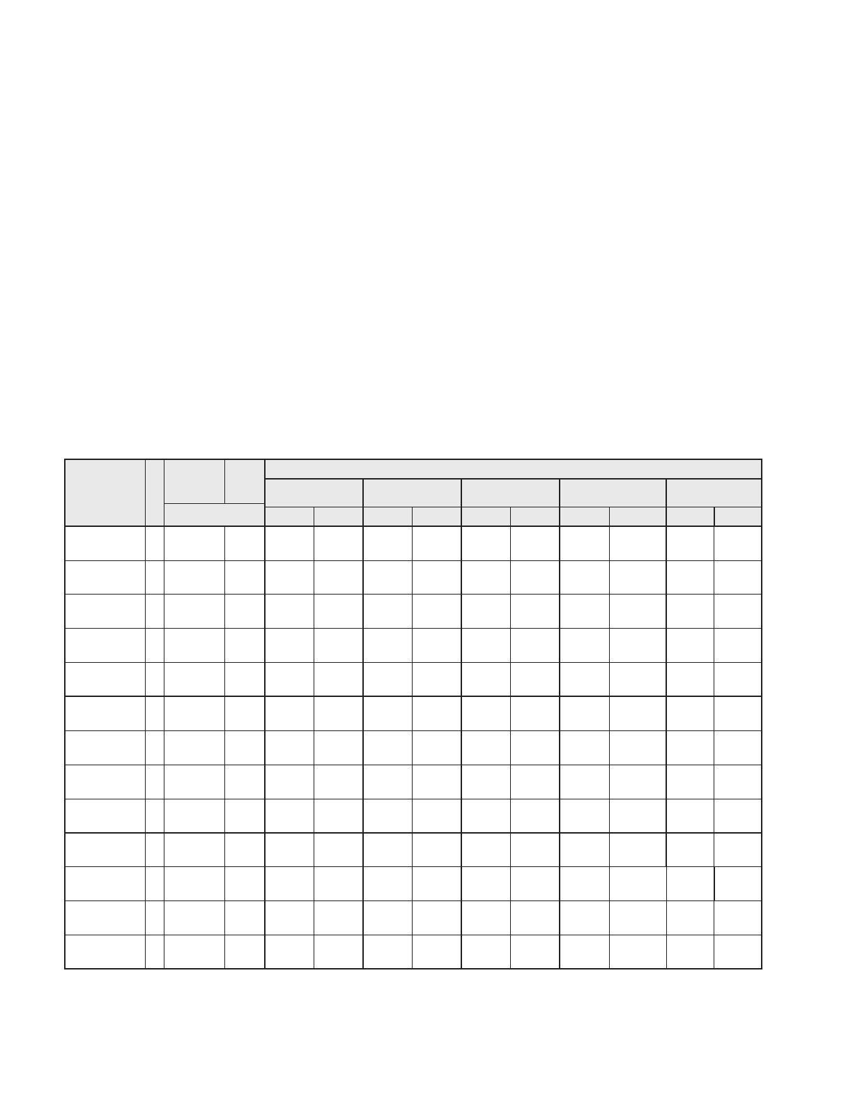
Termination Application Ranges
(Final determining factor is cable insulation diameter. Listed insulation ranges allow + 0.10" (2,54 mm) for shielding.)
Kit Number BIL
(kV)
Insulation
Range
Min - Max
Cable
O. D.
Max
Conductor Size Range (AWG and kcmil)
5 kV 8 kV 15 kV 25/28 kV 35 kV
inch (mm)
100% 133% 100% 133% 100% 133% 100% 133% 100% 133%
7620-T-95-3G 95
0.33 - 0.50
(8,4-12,7)
2.20
(55,8)
8-2 6- 4 6- 4 6- 4
7621-T-95-3G 95
0.50 - 0.70
(12,7-17,8)
2.80
(71,1)
1-3/0 2-2/0 2-2/0 2-2/0
7623-T-95-3G 95
0.70 - 0.92
(17,8-23,4)
3.30
(83,8)
4/0-350 3/0-350 3/0-350 3/0-350
7624-T-95-3G 95
0.92 - 1.18
(23,4-30,0)
3.90
(99,1)
400-500 400-500 400-500 400-500
7625-T-95-3G 95
1.18 - 1.52
(30,0-38,6)
4.50
(114,3)
700-1000 700-1000 700-1000 700-1000
7621-T-110-3G 110
0.50 - 0.70
(12,7-17,8)
2.80
(71,1)
1-3/0 2-2/0 2-2/0 2-2/0 2-1
7622-T-110-3G 110
0.70 - 0.92
(17,8-23,4)
3.30
(83,8)
4/0-350 3/0-350 3/0-350 3/0-350 1/0-4/0 2-3/0
7624-T-110-3G 110
0.92 - 1.18
(23,4-30,0)
3.90
(99,1)
400-500 400-500 400-500 400-500 250-350 4/0-350
7625-T-110-3G 110
1.18 - 1.52
(30,0-38,6)
4.50
(114,3)
700-1000 700-1000 700-1000 700-1000 500-750 500-750
7693-T-150-3G 150
0.70 - 0.92
(17,8-23,4)
3.30
(83,8)
4/0-350 3/0-350 3/0-350 3/0-350 1/0-4/0 2-3/0 1-1/0
7694-T-150-3G 150
0.92 - 1.18
(23,4-30,0)
3.90
(99,1)
400-500 400-500 400-500 400-500 250-350 4/0-350 2/0-250 1-4/0 1/0-3/0
7695-T-150-3G 150
1.18 - 1.52
(30,0-38,6)
4.50
(114,3)
700-1000 700-1000 700-1000 700-1000 500-750 500-750 350-500 250-500 4/0-500 1/0-350
7696-T-150-3G 150
1.53 - 1.81
(38,8-46,0)
5.40
(137,2)
1000 750 500-750 500-750 350-750
Table 1
78-8127-6976-4 Rev D 3
1.0 Prepare Cable
1.1 Determine cable jacket removal length required for correct phase spacing and bolted terminal lug connections
([A] + [B] Figure 1; based on the longest phase to be connected). Allow for dimension [C] as needed.
NOTE: Individual phase length and separation dimensions vary according to specific installation and equipment
design requirements. They must, therefore, be determined by the installer and must conform to accepted
engineering practices. Max phase length = 4 ft (121,9 cm)+ termination length (from table in Figure 18, page 13)
1.2 Remove cable jacket, armor, bedding (inner sheath) and core fillers according to Figure 1 dimensions. Secure
each copper tape shield end with a temporary band of vinyl tape (Figure 1).
Note: DO NOT DISCARD LEFTOVER JACKET MATERIAL.
Temporary Bands of
Vinyl Tape
Ground Wire
Copper T
ape Shield
2” (51 mm)
Armor
[A]
Jacket
Removal
Length
[A] + [B]
[B]
[C]
Figure 1
4 78-8127-6976-4 Rev D
2.0 Install Shield Grounding Braid Assembly & Re-route Cable Ground Wire(s)
2.1 Position ground braid assembly over cable with assembly connector aligned to edge of armor (Figure 2).
Note: For single ground wire cables, apply assembly to side opposite cable ground wire. Assembly connector
should not overlap armor.
Hint: Use temporary vinyl tape wraps as needed to assist in holding braid assembly to cable (Figure 2).
2.2 Attach Ground Braid Assembly Legs to Cable Phase Metallic Shields
(a.) Short (Center) Braid Tail – Position ground braid assembly as shown (Figure 2). Wrap short, center ground
braid tail around metallic shield of first cable core. Trim excess braid length to prevent overlap (Figure 2).
Secure ground braid to cable metallic shield using small constant-force spring (Figure 2). Spring and braid
leg should be wrapped in the same direction. Cinch (twist with hand) constant-force springs to tighten.
(b.) Install Second & Third Ground Braid Tails-Wrap the second and third ground braids around core legs to
adjust length . Position ground braid tails so all constant force springs are equal distance from the cable
armor.
2.3 Apply two highly-stretched half-lapped layers of Scotch
®
Super 33+
Vinyl Electrical Tape over constant-force
springs (Figure 2).
Trim Here
Metallic
Shield
Connector
Cable Armor
Vinyl Tape
( typical )
Braid Assembly Leg
7.0"
(178 mm)
Scotch® Super 33+™ Vinyl
Electrical Tape
Constant Force Spring
Figure 2
78-8127-6976-4 Rev D 5
2.4 Measure distance [J] (Figure 3). Retrieve previously removed cable jacket material. Cut a straight piece to
dimension [J] and wrap it around cable phases beneath ground strap assembly and cable ground wire. Secure
jacket section in place using Scotch® Vinyl Electrical Tape Super 88 (wide vinyl tape) (Figure 3).
Note: Temporarily remove vinyl tape wrap on ground braid.
Scotch® Vinyl Electrical Tape Super 88 (Wide Vinyl Tape)
Side View
Bottom View
Ground Wire
[J]
Figure 3
6 78-8127-6976-4 Rev D
2.5 Fill one armor valley section with tightly-wrapped layers of Scotch® Electrical Shielding Tape 24 (Figure 4).
2.6 Secure ground braid assembly to cable armor using large constant force spring (Figure 4). Once spring has been
applied, cinch (twist with hand) to tighten.
2.7 Apply one half-lapped layer of Scotch
®
Super 33+™
Vinyl Electrical Tape over large constant force spring and
cable armor (Figure 4).
Note: Apply Scotch®
Super 33+™
Vinyl Electrical Tape to hold down ground strap (Figure 4).
Scotch® Super 33+™ Vinyl Electrical Tape
Scotch® Electrical Shielding Tape 24:
Fill To Level Of Armor High Points
Large Constant Force Spring
Figure 4
2.8 Bind cable ground wire with four half-lapped layers of Scotch® Vinyl Electrical Tape Super 88
(wide vinyl tape) (Figure 5). Limit width of tape wrapping to approximately 2-1/2” (63,5 mm).
Bottom View
2-1/2"
(63.5 mm)
Scotch® Vinyl Electrical Tape Super 88 (Wide Vinyl Tape)
Figure 5
78-8127-6976-4 Rev D 7
2.9 Loop cable ground wire back over armor (Figure 6). Adjust ground wire position over cable jacket to run
parallel with tail of ground braid assembly.
Note: Do not make sharp or tight bends in ground wire. Ground wire loop should not extend beyond edge of
protective jacket section as shown.
Do not extend wire loop beyond this edge
Rotated View of Cable
Figure 6
2.10 Apply two half-lapped layers of Scotch® Vinyl Electrical Tape Super 88 (wide vinyl tape) over looped ground
wire area (Figure 7).
Scotch® Vinyl Electrical Tape Super 88 (Wide Vinyl Tape)
Figure 7
2.11 Wrap two strips of Scotch®
Mastic Strip 2230 (one on top of the other) over cable jacket. Locate the mastic
strip directly under the shield braid solder block and ground wire (Figure 8).
Note: It will be necessary to temporarily remove vinyl tape over ground braid tail to complete this step.
Two Strips of Scotch® Mastic Strip 2230
Under Ground Wire & Shield Braid Tail
Figure 8
8 78-8127-6976-4 Rev D
2.12 Separate ground wire strands over strips of Scotch
®
Mastic Strip 2230 as shown (Figure 9).
Hint: Directly over the mastic seal strips, lift and bend the ground wire 90°. Reverse twist the ground conductor
to open strands. Use a screwdriver to aid in separating the strands. On 19 strand wire with reverse twist
innerconductors, twist ground wire in the opposite direction to aid in separating the inner-conductors. Flatten,
straighten and re-position the separated ground conductors. Be careful not to damage ground wire.
Two Strips of Scotch® Mastic Strip 2230
Separated Ground Wire Strands
Wide Vinyl Tape
Figure 9
2.13 Apply one Strip of Scotch
®
Mastic Strip 2230 around ground wire strands (Figure 10). Apply one mastic seal
strip around solder block section of ground braid tail. Align mastic strip wraps with previously applied mastic
strip band around cable jacket.
Note: Avoid crossing individual wires at mastic seal location.
Scotch® Mastic Strip 2230 Over Solder Block Section
Scotch® Mastic Strip 2230 Over Ground Wire Strands
Wide Vinyl Tape
Figure 10
78-8127-6976-4 Rev D 9
2.14 Wrap two additional strips of Scotch
®
Mastic Strip 2230 directly over previously applied mastic. (Figure 11).
2.15 Cover mastic seal area with two highly stretched half-lapped layers of Scotch® Vinyl Electrical Tape Super 88
(wide vinyl tape.)
Two Strips of Scotch® Mastic Strip 2230 ( Final Layer )
Scotch® Vinyl Electrical Tape Super 88 (Wide Vinyl Tape)
Figure 11
2.16 Install cold shrink jacket extension assembly. Align the jacket seal tube (not the plastic support core) to overlap
ground wire seal area by approximately 1/4” (6 mm). To install, pull loose core end, while unwinding counter-
clockwise around the cable. (Figure 12).
2.17 Bind cable ground wire and ground braid tail to cable jacket using Scotch® Vinyl Electrical Tape Super 88
(wide vinyl tape) (Figure 12). Apply at least eight tape layers and wrap only to width of tape roll.
1/4" (6 mm)
Pull Tab
Scotch® Vinyl Electrical
Tape Super 88 Binding
Figure 12
10 78-8127-6976-4 Rev D
3.0 Install Cold Shrink Silicone Rubber Breakout Boot Assembly
3.1 Inspect breakout boot assembly and confirm that all loose plastic core ends are free as shown (Figure 13).
Finger
Neck
Neck Core
Boot Neck
Boot Finger
Finger Core
Loose Core Ends
Loose Core
End
Loose Core End
Loose Core End
Figure 13
3.2 To ensure that the breakout boot can be fully seated into the breakout area of the cable, it will be necessary to
unwind a few turns of each finger core.
Caution: Do not unwind too far such that boot fingers begin to collapse.
3.3 Hold loose neck-end core ribbon to one side so that it can not become trapped between cable phases. Slide boot
assembly over cable end; guiding individual cable cores through boot assembly fingers.
Hint: View end of cable through finger cores to ease cable phase insertion.
3.4 Slide breakout boot assembly onto cable as far as it will go. Large neck-end should fully extend over
previously-installed jacket sealing assembly tube.
Hint: Spreading cable phases while sliding the boot assembly can ease the installation.
3.5 Remove large neck-end core. Grasping loose core ribbon end , pull and unwind counter-clockwise around cable.
3.6 Remove each finger core. Grasping loose core ribbon end , pull and unwind counter-clockwise around each
cable phase leg.
4.0 Install Silicone Rubber Rejacketing Sleeves
4.1 From the chart below, determine the correct [A] (Figure 14) dimension for the termination being installed.
Kit Number Dimension [A]
7620-T-95-3G 6.75" (171 mm)
7621-T-95-3G
7623-T-95-3G
7624-T-95-3G
7625-T-95-3G
5.50" (140 mm)
7621-T-110-3G
7622-T-110-3G
7624-T-110-3G
7625-T-110-3G
8.5" (216 mm)
7693-T-150-3G
7694-T-150-3G
7695-T-150-3G
7696-T-150-3G
12.0" (305 mm)
78-8127-6976-4 Rev D 11
4.2 Place a vinyl tape marker on each cable phase leg at dimension [X] (Figure 14).
Note: [X] = [A](From chart above) + [B](Lug barrel depth). Allow for crimp growth when using aluminum lugs.
4.3 Determine required rejacketing sleeve length for each phase leg (Distance [S], Figure 14). Be sure to include
1.0" (25 mm) breakout boot finger overlap in measurement.
[S]
[X]
[B]
[A]
1.0" (25 mm) Overlap
Marker Tape
Figure 14
4.4 Using scissors, trim rejacketing sleeve assembly to length required (Figure 15). Cut tubing and inner braid
together.
Note: Inner polyester braid should extend approximately 3.0” (76 mm) beyond rejacketing tube end before cutting.
There is no need for termination-end braid exposure.
Expose
Approximately
[S]
Termination End
Breakout Boot End Rejacketing Sleeve
Figure 15
4.5 Guide one rejacketing sleeve assembly over each cable phase leg (Figure 16). Push sleeve assembly from
above. Continuously guide the free end, maintaining sleeve-to-cable-core alignment.
Right
Wrong
Figure 16
12 78-8127-6976-4 Rev D
4.6 Slide rejacketing sleeve until inner polyester braid is adjacent to breakout boot finger (Figure 17).
4.7 Fold outer silicone tubing back on itself for 1.0" (25 mm) (Figure 17) and trim off exposed polyester braid.
Note: Do not damage silicone tubing while cutting. Sleeve assembly may be rotated to ease trimming. When doing
so, rotate in the direction of the cable copper tape shield wrap.
1.0" (25 mm)
Silicone Tube Fold-back
Polyester Braid
Rejacketing Sleeve
over Marker Tape
Step 4.6
Step 4.7
Figure 17
4.8 Slide rejacketing sleeve assembly down until folded tube contacts edge of breakout boot finger (Figure 17).
4.9 Pull folded silicone tube section down onto breakout boot finger (Figure 17).
Note: Rejacketing tube end should align with upper edge of installed marker tape (Figure 17). Minor tube
adjustments can be made as needed.
78-8127-6976-4 Rev D 13
5.0 Install 3M
Cold Shrink QT-III Silicone Rubber Termination Assemblies
5.1 Prepare cable phase legs according to dimensions shown (Figure 18).
Note: It is imperative to remove all remnants of the semi-con layer, even if the semi-con layer comes off as one
layer. There should not be any remaining black areas, or particles, on the cable insulation layer.
A
B
C
D
Rejacketing Sleeve
Kit Number Dimension A Dimension B Dimension C Dimension D
7620-T-95-3G 6.75" (171 mm) Lug Depth* 2.0" (51 mm) 1.0" (25 mm)
7621-T-95-3G
7623-T-95-3G
7624-T-95-3G
7625-T-95-3G
5.50" (140 mm) Lug Depth* 2.5" (64 mm) 1.25" (32 mm)
7621-T-110-3G
7622-T-110-3G
7624-T-110-3G
7625-T-110-3G
8.5" (216 mm) Lug Depth* 2.5" (64 mm) 1.25" (32 mm)
7693-T-150-3G
7694-T-150-3G
7695-T-150-3G
7696-T-150-3G
12.0" (305 mm) Lug Depth* 2.5" (64 mm) 1.25" (32 mm)
*Allow for crimp growth when using aluminum lugs and connectors.
Figure 18
Aluminum Lug and Connector
Growth Allowance
2 - 350
1/4” (6 mm)
400 - 650
1/2" (13 mm)
750–1000
3/4" (19 mm)
1250–2000
Field Determined
5.2 Secure cable copper tape shield ends with 3M
EMI Copper Foil Shielding Tape 1181 Strips. (Figure 19).
Rejacketing Sleeve
3M™ EMI Copper Foil Shielding
Tape 1181 Strips
Figure 19
5.3 Secure rejacketing sleeve with two half-lapped layers of Scotch
®
Super 33+
Vinyl Electrical Tape (Figure 20).
Start taping 0.75" (19 mm) over rejacketing sleeve, extend 0.25" (6 mm) over cable metallic shield and return to
starting point.
Note: Do not cover 3M
EMI Copper Foil Shielding Tape 1181 Strips.
0.75" (19 mm)
0.25" (6 mm)
Rejacketing Sleeve
Scotch® Super 33+™ Vinyl
Electrical Tape
Figure 20
14 78-8127-6976-4 Rev D
5.4 Place a termination installation marker tape at position [M] (Figure 21).
[M]
Marker Tape
Figure 21
Kit Number Dimension M
7620-T-95-3G 4.0" (102 mm)
7621-T-95-3G
7623-T-95-3G
7624-T-95-3G
7625-T-95-3G
5.0" (127 mm)
7621-T-110-3G
7622-T-110-3G
7624-T-110-3G
7625-T-110-3G
5.0" (127 mm)
7693-T-150-3G
7694-T-150-3G
7695-T-150-3G
7696-T-150-3G
5.0" (127 mm)
5.5 Install terminal lugs.
Note: Special Case – When lug spade dimension is larger than inside diameter of white plastic
termination core, position termination assemblies over cable phase legs prior to installing lugs.
Remove inner red shipping core from each termination assembly by pulling and unwinding the loose red core
ribbon. Position one termination over each cable phase leg. Each termination assembly must be positioned with
its loose white core ribbon end directed toward the open (cut) end of the cable. DO NOT REMOVE CORE
AT THIS TIME. Continue with lug installations.
(a.) For Aluminum Conductors - Thoroughly wire brush conductor strands to remove aluminum oxide
layer. Immediately insert conductor into terminal lug barrel as far as it will go.
(b.) Ensure that each lug face is parallel to equipment bushing or lug connection interface (Figure 22).
Last Crimp
First Crimp
Figure 22
(c.) Crimp terminal lug according to manufacturer's recommendations. Start at the upper end as shown
(Figure 22). Remove all traces of oxide inhibitor that may have come out of lug barrel during crimping.
(d) If abrasive must be used:
1. Use on insulation only. DO NOT USE ABRASIVE ON SEMI-CON INSULATION SHIELD!
2. Use only aluminum oxide abrasive; grit 120 or finer.
78-8127-6976-4 Rev D 15
3. Be careful not to reduce the cable insulation diameter below that allowed by the kit.
(e.) Thoroughly clean primary insulation and lug barrel area using solvent wipe from supplied 3M
Cable
Cleaning Preparation Kit CC-2.
Note: DO NOT ALLOW SOLVENT TO TOUCH SEMI-CON INSULATION SHIELD.
5.6 Install 3M
Cold Shrink QT-III Silicone Rubber Termination assemblies.
(a.) Remove the inner red shipping core from the termination assembly by pulling and unwinding the loose red
core end.
(b.) Position the termination assembly with the loose white core ribbon directed toward the terminal lug.
(c.) Align the base of the termination (not the plastic core) with the installation marker tape as shown
(Figure 23).
(d.) Grasp the loose white core ribbon. Pull and unwind counter-clockwise around cable end (Figure 23).
Note: Once the termination body makes contact, there is no need to continue supporting the assembly. DO NOT
PULL OR PUSH ON THE TERMINATION ASSEMBLY WHILE UNWINDING THE CORE.
(e.) Remove the installation marker tape.
Marker Tape
Termination Base Aligned With Marker Tape Edge
Rejacketing Sleeve
Figure 23
5.7 Connect shield braid tail and cable ground wire to system ground (earth) according to normal practice.
3M, Super 33+ and Scotch are trademarks of 3M Company.
Important Notice
All statements, technical information, and recommendations related to 3M's products are based on information believed to be reliable,
but the accuracy or completeness is not guaranteed.
Before using this product, you must evaluate it and determine if it is suitable for
your intended application.
You assume all risks and liability associated with such use.
Any statements related to the product which are not
contained in 3M's current publications, or any contrary statements contained on your purchase order shall have no force or effect unless
expressly agreed upon, in writing, by an authorized officer of 3M.
Warranty; Limited Remedy; Limited Liability.
This product will be free from defects in material and manufacture at the time of purchase.
3M MAKES NO OTHER WARRANTIES
INCLUDING, BUT NOT LIMITED TO, ANY IMPLIED WARRANTY OF MERCHANTABILITY OR FITNESS FOR A PARTICULAR PURPOSE.
If this product is defective within the warranty period stated above, your exclusive remedy shall be, at 3M's option, to replace or repair the
3M product or refund the purchase price of the 3M product.
Except where prohibited by law, 3M will not be liable for any indirect,
special, incidental or consequential loss or damage arising from this 3M product, regardless of the legal theory asserted.
3
Electrical Markets Division
6801 River Place Blvd.
Austin, TX 78726-9000
800.245.3573
Fax 800.245.0329
www.3M.com/electrical
Please Recycle. Printed in USA.
© 3M 2013. All Rights Reserved.
78-8127-6976-4 Rev D
  • Page 1 1
  • Page 2 2
  • Page 3 3
  • Page 4 4
  • Page 5 5
  • Page 6 6
  • Page 7 7
  • Page 8 8
  • Page 9 9
  • Page 10 10
  • Page 11 11
  • Page 12 12
  • Page 13 13
  • Page 14 14
  • Page 15 15
  • Page 16 16

3M Cold Shrink QT-III 3/C Termination Kit 7693-T-150-3G, Tape/Wire/UniShield®, 5-25 kV, Insulation OD 0.70-0.92 in, 3/kit Operating instructions

Type
Operating instructions

Ask a question and I''ll find the answer in the document

Finding information in a document is now easier with AI