Page is loading ...

S–1000
Thank you for your purchase of the Krell
®
S–1000. The S–1000 delivers a seamless
home theater experience, integrating fully with the latest video displays and
audio/video source components. HDMI
TM
video switching rounds out a full comple-
m
ent of advanced Krell technologies including discrete Class A, direct-coupled cir-
cuitry with balanced outputs. A new, easy to access on-screen menu system
makes customization a snap.
The S–1000 features Dolby Digital 5.1, Dolby Digital EX, DTS-ES 6.1, DTS NEO:6,
and Dolby Pro Logic II processing, in addition to nine proprietary Krell Music
Surround modes. An RS-232 port insure compatibility with third party controllers
and allows upgrades to software via Flash memory for future surround sound for-
mats and design enhancements.
The S–1000 must be placed on a firm, level surface where it is not exposed to drip-
ping or splashing.
The ventilation grids on the top and bottom of the S–1000 must be unobstructed at
all times during operation. Do not place flammable material on top of or beneath the
preamplifier.
Before making connections to the S–1000, ensure that the power is off and other
components are in mute or stand-by mode. Make sure all cable terminations are of
the highest quality, free from frayed ends, short circuits, or cold solder joints.
THERE ARE NO USER-SERVICEABLE PARTS INSIDE AN S–1000.
The S–1000 Surround Preamp/processor offers a high degree of flexibility via an on-
screen menu system. To setup your S–1000 quickly:
1. Connect your S–1000 to the rest of the components in your system, using
Table 1 on page 4 as a guide. Please note:
On Screen Display (OSD). The S–1000 has three OSD outputs: component,
S-video, and composite. There is no OSD available from the HDMI
TM
output.
To View the Setup Menu. Connect any of the OSD outputs on the S–1000 to
the appropriate input on your video display
. Press the r
emote contr
ol menu
key. The front panel display reads MENU MODE and all OSD outputs activate
simultaneously
. T
une the video display input to match the selected OSD video
connection.
2.
Enter the setup menu. The
MAIN MENU scr
een appears on the video display.
3. Using the video display (OSD) and the remote, select
LISTENING ROOM SETUP.
The LISTENING ROOM SETUP screen appears.
4. Select SPEAKER SETUP. The SPEAKER SETUP screen appears. Scroll through the
available options and select your loudspeaker setup.
5. Select SPEAKER DISTANCE and enter information about the placement of your
loudspeakers relative to your listening position.
6. Select
SPEAKER LEVEL and calibrate the volume of your loudspeakers.
Please contact your authorized dealer
, distributor
, or Kr
ell if you have any ques
-
tions not addressed in this quick setup guide.
Krell Industries, Inc. • 45 Connair Road • Orange, CT 06477-3650 USA
TEL 203-298-4010 • FAX 203-891-2028 • E-MAIL krell@krellonline.com
WEB SITE http://www.krellonline.com
S
URROUND
PREAMP/PROCESSOR
WITH HDMI
TM
TECHNOLOGY
Quick Setup Guide
OVERVIEW
GETTING STARTED
WARNINGS
This product complies with the EMC
directive (89/336/EEC)
and the low-voltage directive
(73/23/EEC).
IMPORTANT:
ACCESSING THE
ON SCREEN DISPLAY
Krell S–1000 1

2 Krell S–1000
DVD
C
A
B
L
E
SAT
V
CR
T
V
C
D
TUNER
A
UX
G
AME
TAPE/VCR2
POWER
RECALL
S
AVE
B
ALANCE
CENTER
S
URR/BACK
S
UB
PRE AMP
S
TEREO
MODE 1
MODE 2
PRO LOGIC II
7 2421 20
19 15 16 17 182625 14
10
11
12
2713 23221 34
8 965
2
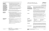
Figure 1 The S–1000 Front Panel
BASIC
OPERATION
1
Power Button/Pre Key
Switches the S–1000 from
stand-by to operational mode,
and to switch the 12 VDC out
-
put (12 V trigger) on and off.
2
Power/Stand-by LED
Stand-by Mode.
When the
AC power cor
d is plugged
into the wall, the LED illumi-
nates in red: the S–1000 is in
stand-by mode.
Operational Mode. When the
power/stand-by button is
pressed, the LED illuminates
in blue: the S–1000 is in the
operational mode.
3
Infrared Sensor
Receives commands fr
om the
S–1000 remote control.
4 Infrared Emitter
Sends the S
–1000
remote
operation code to a learning
remote.
INPUT DEVICE
SELECTION
The S–1000 is equipped with ten
input device selection buttons on
the front panel and corresponding
keys on the remote control. If
properly configured, the S–1000
automatically engages the cor-
rect video and audio inputs when
you press the device selection
button.
5 DVD Button/LED/Key
6 Cable Button/LED/Key
7 SAT Button/LED/Key
8 VCR Button/LED/Key
9 TV Button/LED/Key
10 CD Button/LED/Key
11 Tuner Button/LED/Key
12
Aux Button/LED
and Aux 1 Key
Selects an auxiliary device:
phono, tape, or an additional
DVD, LD, CD, or VCR.
13
Game Button/LED
and Aux 2 Key
14 Tape/VCR2 Button/LED/Key
Playsback pre-recorded
tapes, and compar
es the out
-
put signal of an analog tape
recorder to an audio source.
PROCESSING
MODE
15
Stereo Button/LED/Key
Selects ster
eo decoding.The
red LED illuminates when this
function is engaged.
16 Mode 1 Button/LED/Key
17 Mode 2 Button/LED/Key
Selects available processing
modes (such as Dolby Digital,
DTS, PLII Movie, etc.) for
incoming signals from an
audio source.
The default mode for a signal
is always stored in Mode 1.
Use the Mode 1 button or key
to select the default mode. All
modes that can be used for
the same signal are automati-
cally stored in Mode 2. Use
the Mode 2 button or key to
scroll through these other
modes. The last mode dis-
played in Mode 2 is the se-
lected mode. Based on the
sour
ce signal, the
S
–1000
automatically selects the
assigned mode for the avail
-
able signal.
18
Pr
o Logic II
Button/LED/Key
Selects Dolby Pro Logic II
modes for Dolby Surround
encoded material, including
laser discs, videotapes, televi-
sion broadcasts, and com-
pact discs. The red LED illu-
minates when Dolby Pro
Logic II decoding is selected.
Note: These modes are
selected automatically if
Dolby Digital source material
is encoded for Pro Logic. To
turn off these modes, press
the Pro Logic II button.
19 Preamp Button/LED/Key
Sends the signal from an ana-
log input directly to the vol-
ume control, with no digital
processing, using the analog
stage of the preamplifier.
This avoids possible digital
signal degradation. Used for
components with a high qual-
ity signal, such as the Krell
Evolution 505 CD Player
.
Note: This feature is available
with a signal fr
om an analog
input. If you attempt to use it
with a signal from a digital
input, the OSD r
eads
NOT
ALLOWED
DISPLA
Y
WINDOW
20 Front Panel Display
Provides status messages for
S-1000 operations, including
volume and balance level,
decoding mode, and zone
infor
mation. When a new
device is selected, the physi-
cal inputs ar
e displayed. The
display turns of
f after 60 sec
-
onds of inactivity.
FRONT PANEL
AND REMOTE
FUNCTIONS

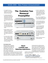
REMOTE ONLY
FUNCTIONS
28
Amp Key
29 Menu Key
30 Pr
ev Key
31 Mute Key
32 Enter Key
33 Right Directional Key
All other functions on the
remote control duplicate front
panel functions.
The following keys ar
e not
active on the S–1000 remote:
MAIN, Z2, THX
Note:
6 The L
D
key on the r
emote
activates the cable device
button (6) on the front panel.
HOW TO NAVIGATE
THE SETUP MENU
1 Press the menu key (29) to
enter and exit the setup
menu.
2
Press the direction keys (33)
to scroll from line to line,
and to scroll through options
within a line.
3 Pr
ess the enter key (32) to
select a line and set an
option.
4 Press the prev key (30) to
return to the previous screen.
5 Press the pre key (1) to exit
the setup menu; the S–1000
reverts to stand-by.
Krell S–1000
3
INDIVIDUALIZED
CHANNEL TRIM
The center, surr/back, and sub
buttons or keys make temporary
loudspeaker output adjustments
of +/- 10 dB. These temporary
adjustments revert to 0 dB when
a new device is selected or when
the system is powered down.
21 Center Button/Key
Adjusts the center loudspeak-
er volume. Press the center
button or key, then use the
volume knob or up and down
directional keys to make the
adjustments.
Phantom Center
.
Pr
ess the
center button or key twice
activate. Press the center but-
ton twice again to deactivate.
22 Surr/Back Button/
Rear Key
Adjusts the volume of the sur-
round and back loudspeakers.
Press the surr/back button,
then use the volume knob or
up and down direction keys to
adjust the surround loud-
speakers. To adjust the back
loudspeakers, press the surr/
back button.
SURROUND TRIM
appears on the front panel
display. Press the surr/back
button again. BACK appears
on the front panel display.
Then use the volume knob or
the up and down directional
keys to adjust the volume of
the back loudspeakers.
23 Sub Button/Key
Adjusts the subwoofer vol-
ume. Press the sub button or
key, then use the volume
knob or the up and down
directional keys to adjust the
subwoofer volume.
24 Balance Button/Key
Adjusts the main left/right
loudspeaker balance. Press
the balance button or key,
then use the volume knob or
the up and down directional
keys to adjust the balance.
Balance levels show numeri-
cally on the front panel dis-
play. Balance may be adjust-
ed in .5 dB increments, up to
6 dB. The center position is
displayed as BAL 0.
Balance level keys revert to
their original function as vol-
ume level controls after 3
seconds of inactivity.
PROCESSOR
FUNCTIONS
25 Save Button/Key
Saves system configuration
settings. Press and hold this
button or key to activate. This
function is also used to pro-
gram a learning remote.
26 Volume Knob/Keys
Scrolls through menu selec-
tions, adjust output for the
entire system, and adjusts
volume and balance levels
for the center loudspeaker,
surround/back loudspeakers,
and subwoofer. Volume and
balance levels appear in the
front panel display.
27 Recall Button
Recalls previously stored sys-
tem configuration settings.
Returns configuration settings
to factory default: With the
S–1000 in the operational
mode, hold the recall button
and press the power button.
REMOTE ONLY
FUNCTIONS
28 Amp Key (Power Amp Key)
Operates IR controllable
power amplifiers, such as all
Krell Evolution amplifiers.
29 Menu Key
Accesses the setup menu
and on-screen menu display.
30 Prev Key
Return to the previously dis-
played setup menu screen.
31 Mute Key
Mutes the S–1000 output.
When this function is active,
V
OLUME MUTE
appears in the
front panel display.
32 Enter Key
Accepts setup menu selec-
tions, accept an input device
selection, or displays current
system conditions.
33
Directional Keys
Up and Down Directional
Keys.
Adjust volume, and
adjust balance if the balance
function is activated.
In the operational mode, the
up and down directional keys
select EQ memory.
Right Directional Key. In the
operational mode, the right
arrow key engages Digital
Room EQ.
All Directional Keys. In the
setup menu, all four directional
keys navigate the on-screen
menus.
S–1000 Front Panel and Remote Functions continued
Figure 2 The S–1000 Remote
28
33
1
32
21
6
11
16
17
24
5
10
19
15
29
30
14
8
18
12
7
22
31
23
9
13

DEVICE S–1000 CONNECTIONS FACTORY DEFAULT DECODING MODES
Digital Analog
V
ideo
Audio Audio Dolby 2.0 Dolby 5.1 DTS 5.1 PCM Analog
DVD
Component 1 COAX 1 S1 Dolby D+ Dolby D 5.1 DTS 5.1 Dolby PLII Dolby PLII
Dolby PLII Movie Movie Movie Movie
CABLE HDMI
TM
2 COAX 3 S4 Dolby D+ Dolby D 5.1 DTS 5.1 Dolby PLII Dolby PLII
Dolby PLII Movie Movie Movie Movie
SA
T
HDMI
TM
1
OPT 1 S3 Dolby D+ Dolby D 5.1 DTS 5.1 Dolby PLII Dolby PLII
Dolby PLII Movie
Movie
Movie Movie
VCR S-Video 2 Disabled VCR N/A N/A N/A N/A Dolby PLII
Movie
TV Composite 1
COAX 2
S2 Dolby D+ N/A N/A N/A Dolby PLII
Dolby PLII Movie Movie
CD Disabled Disabled B1 N/A N/A N/A N/A Preamp
TUNER Disabled Disabled S5 N/A N/A N/A N/A Preamp
AUX Disabled Disabled 7.1 N/A N/A N/A N/A N/A
GAME Component 2 OPT 2 S6 N/A Dolby D 5.1 DTS 5.1 Dolby PLII Preamp
TAPE Composite 3
Disabled
Tape
N/A
N/A
N/A N/A Preamp
P
OWER
H
DMI OUT
H
DMI 4
HDMI 3
HDMI 2
HDMI 1
1
2VDC OUT
12VDC
IN
1
2 34
Processor
R
C-5
IN
S
BL
SL
C
L
R
SW
SR SBR
5
0/60 Hz
RS-232
MADE IN USA
D
IGITAL AUDIO
O
UT
1
3
2
4
1
2
3
4
SBL
SBR
SL
S
R
ANALOG AUDIO OUTPUTS
COMPOSITE VIDEO
OSD
OUT
3
1
2
4
S-VIDEO
1
3
2
4
OUT
OSD
OSD
C
OMPONENT VIDEO
I
N
Pr
Pb
Y
3
PrPb
Y
1
2
M
ULTI-CHANNEL INPUTS
L
C SL
S
BL
R
SW
S
R
SBR
R
C
L
S
W
A
NALOG AUDIO INPUTS
R
L
NO USER SERVICEABLE PARTS INSIDE
L
R
1
2
3
45
6
7
T
APE
IN
O
UT
L
R
L
R
VCR
INOUT
51 50 56 53 5247 46 49 48 55 58
42 36 41 43 4434 37 38 39 40 45 545935
57
Figure 3 The S–1000 Back Panel
Table 1 S–1000 Connections and Corresponding Factory Default
Decoding Modes, by Device
Connect the S–1000 to the rest of the components in your system, using this table as a guide.
ANALOG AUDIO INPUTS
AND OUTPUTS
34 Balanced Analog
Audio Outputs
35 Single-ended
Analog Audio Outputs
36 Balanced Analog
Audio Inputs
37 Tape In Left and Right
38 Tape Out Left and Right
39 VCR In Left and Right
40 VCR Out Left and Right
41 Single-ended
Analog Audio Inputs
42 7.1 Audio Inputs
DIGITAL AUDIO
INPUTS AND OUTPUTS
43 Optical Digital Audio Inputs
44 Coaxial Digital Audio Inputs
45 Digital Audio Outputs
VIDEO INPUTS AND
OUTPUTS
46 S-video Outputs
47 S-video Inputs
48 Composite Video Outputs
49 Composite Video Inputs
50 Component Video Outputs
51 Component Video Inputs
52 HDMI
TM
Output
53 HDMI
TM
Inputs
BACK PANEL REMOTE
CONTROL CONNECTIONS
54 Comm Port RS-232
Remote Connector
55 RC-5 In
56 12 VDC In and Out
57 DB 25 Out
POWER
CONNECTIONS
58 Back Panel Power Switch
59 IEC Connector
4 Krell S–1000

Krell S–1000 5
ANALOG AUDIO
OUTPUTS AND INPUTS
34 Balanced Analog
Audio Outputs
Eight balanced analog audio
channel outputs, with XLR
connectors, for the left, cen-
ter, subwoofer, surround left,
surround right, back left, and
back right.
35 Single-ended Audio Outputs
Eight single-ended analog
audio channel outputs, with
RCA connectors, for the left,
center, right, subwoofer, sur-
round left, surround right,
back left, and back right.
36 Balanced Analog
Audio Inputs
One set of balanced inputs
with XLR connectors.
37 Tape In Left and Right
One set of single-ended tape
inputs with RCA connectors.
38 Tape Out Left and Right
One set of single-ended tape
outputs with RCA connectors.
39 VCR In Left and Right
One set of single-ended
inputs with RCA connectors,
for a VCR audio source.
40 VCR Out Left and Right
One set of single-ended out
puts with RCA connectors,
for a VCR audio source.
41 Single-ended Analog
Audio Inputs
Seven sets of single-ended
inputs with RCA connectors.
42 7.1 Audio Inputs
Eight single-ended 7.1 inputs
for multi-channel SACD and
DVD audio devices. These
inputs are analog pass-
thr
ough inputs.
DIGITAL AUDIO INPUTS
AND OUTPUTS
43 Optical Digital Audio Inputs
Four optical digital EIAJ
inputs with TosLink connec-
tors.
44 Coaxial Digital Audio Inputs
Four coaxial digital audio
inputs with RCA connectors.
45 Digital Audio Outputs
Two digital audio outputs and
one coaxial with an RCA con-
nector.
VIDEO INPUTS
AND OUTPUTS
46 S-video Outputs
Two S-video outputs with
DIN connectors. The main S-
video output (labeled OSD
on back panel) includes on-
screen display. When dub-
bing, the second S-video
output does not include on-
screen display.
47 S-video Inputs
Four S-video inputs with DIN
connectors.
48 Composite Video Outputs
Two composite video out-
puts with RCA connectors.
The main composite video
output (labeled OSD on back
panel) includes on-screen
display. For dubbing purpos-
es, the second composite
video output does not
include on-screen display.
49 Composite Video Inputs
Four RCA composite video
inputs with RCA connectors.
50 Component Video Outputs
One set of component video
outputs with RCA connec-
tors. Component video uses
three wires, labeled Y, Pr,
and Pb on the back panel,
to convey the video signal.
These inputs are compatible
with all wideband video
sources.
51 Component Video Inputs
Three sets of component
video inputs.
52 HDMI
TM
Outputs
One HDMI
TM
video output.
53 HDMI
TM
Inputs
Four HDMI
TM
video inputs.
Note: The
S–1000 switches
HDMI
TM
video only. No audio
signal is available via the
HDMI
TM
inputs. There is no
on screen display (OSD)
available from the HDMI
TM
output. When an HDMI
TM
input is assigned to a device,
and the menu key on the
r
emote is pressed, the on
screen menu is available
simultaneously from the
Composite, S-Video and
Component OSD outputs.
BACK PANEL
REMOTE CONTROL
54 Comm Port RS-232
Connector
Sends operational instruc-
tions directly to the S–1000
using an external computer
control system.
55 RC-5 In
Makes custom installation
easy and secure by accept-
ing baseband RC-5 input
commands from hardwired
remote controllers.
56 12 VDC In and Out
Four programmable 12 V out-
puts and one input. Sends a
12 V power on/off signal via a
12 V trigger cable to other
Krell components and to other
devices that incorporate 12 V
power on/off trigger input.
When the S–1000 is in the
operational mode and a trig-
ger is enabled, the 12 VDC
Out provides 12 V of DC out-
put. When the S–1000 is in
the stand-by mode or off, or
if a trigger is not enabled, the
DC output is 0 V.
Note: Trigger 1 is enabled for
all 10 devices.
57 DB 25 Out
One multi-channel audio out-
put via a DB-25 connector.
The DB-25 contains the out-
put connections for all the
output channels (left, center,
right, subwoofer, surround
left, surround right, back left,
and back right). This connec
-
tion also mates with an
optional CAST Output
Module that enables all 8
channels of the
S–1000 to
be connected in CAST.
POWER
CONNECTIONS
58 Back Panel Power Switch
Switches the
S–1000 from
of
f to stand-by.
59 IEC Connector
A standard female IEC power
connector
, for use with the
AC power cord.
BACK PANEL
CONNECTIONS

6 Krell S–1000
STEP 1
Connect the S–1000 to your system, using Table 1 on page 4 as a guide. You are
ready to configure the S–1000 through the interactive on-screen menus in the setup
menu. For best performance, configure the loudspeakers before playing music.
Please note:
On Screen Display (OSD). The S–1000 has three OSD outputs: component,
S-video, and composite. There is no OSD available from the HDMI
TM
output.
T
o View the Setup Menu.
C
onnect any of the OSD outputs on the S–1000 to
the appropriate input on your video display. Press the remote control menu
key. The front panel display reads
MENU MODE and all OSD outputs activate
simultaneously. Tune the video display input to match the selected OSD video
connection.
STEP 2
Enter the setup menu. The MAIN MENU scr
een appears on the video display.
STEP 3
Select LISTENING ROOM SETUP from the MAIN MENU screen. The LISTENING ROOM
SETUP screen appears.
STEP 4
Select SPEAKER SETUP from the LISTENING ROOM SETUP screen. The SPEAKER
SETUP screen appears.
FULL RANGE
Full Range sends 20Hz to 20KHz signals to the loudspeaker. Limited sends infor-
mation fr
om the cr
ossover frequency (see below) to 20KHz to the loudspeaker. The
fr
equencies below the crossover fr
equency are sent to the subwoofer if present;
otherwise, these low frequencies are sent to the full range loudspeakers in the sys-
tem.
SUB
Select NORMAL or ENHANCED to choose the amount of bass infor
mation sent to the
subwoofer.
– NORMAL sends the low frequencies from the limited speakers and the .1 (or
LFE) signal to the subwoofer
.
– ENHANCED sends additional bass information from the left and right loud
speakers to the subwoofer in addition to the low frequencies from the limited
loudspeakers and the .1 (or LFE) signal.
S –1000
-SPEAKER SETUP-
YES
YES
2
YES
FRONT
CENTER
SURROUND
BACK
SUB
CRSOVR
5.1 SURR
!! FULL RANGE ""
FULL RANGE
FULL RANGE
FULL RANGE
NORMAL
80 Hz
SURROUND
Speaker Setup Screen
SYSTEM
CONFIGURATION
QUICK SETUP
Using this screen, you can activate loudspeakers that
are in your system in the left column and select loud-
speaker characteristics in the far right column.
Scroll through the available options and select your
loudspeaker setup.
For a 5.1 system, select NO back speakers.
For a 6.1 system, select 1 back speaker.
For a 7.1 system, select 2 back speakers.
Note
When 1 back speaker is selected, the signal is present at the
left back output.
IMPORTANT:
A
CCESSING THE
ON SCREEN DISPLAY

Krell S–1000 7
System Configuration
Quick Setup, continued
STEP 4 continued
CRSOVR
Crossover selections are 120, 100, 80, 60, and 40 Hz. The standard crossover set-
ting is 80 Hz. Choose the crossover frequency appropriate for your loudspeakers.
The frequencies below the crossover frequency are sent to the subwoofer if a sub-
w
oofer is present; otherwise, these low frequencies are sent to the full range loud-
speakers in the system.
5.1 SURR
Select SURROUND, BACK, or BOTH to choose which loudspeakers in a 6.1 or 7.1
system receive surround information when playing a Dolby Digital 5.1 or DTS 5.1
encoded software.
– SURROUND sends surround channel information to your surround loud
speakers only.
– BACK sends surround channel information to your back loudspeakers only.
– BOTH sends surround channel information to your surround and back loud
speakers simultaneously.
After completing the speaker setup screen, press the previous key twice. The main
menu appears.
STEP 5
Select SPEAKER DISTANCE from the main menu. The SPEAKER DISTANCE screen
appears.
After setting all the speaker distances, pr
ess the previous key twice. The main menu
appears.
S –1000
-ROOM SETUP-
!! LEFT ""
0 FT
L SURR
0 FT
L BACK
0 FT
CENTER
0 FT
SUB
0 FT
C BACK
N/A
RIGHT
0 FT
R SURR
0 FT
R BACK
0 FT
Speaker Distance Screen
This screen enables you to tell the S–1000 the exact
location of each loudspeaker in your system.
When you access the SPEAKER DISTANCE screen, the
cursor is blinking at the
LEFT loudspeaker. Use the
direction and enter keys to navigate the screen, select
loudspeakers, and enter the correct distance (0 to 30
feet) from your main listening position to the loud-
speaker.
Note
Any speaker not configured in the SPEAKER SETUP menu
displays N/A (not available) on the speaker distance screen.
Save and Recall Customized Settings / Restore Factory Default System Settings
SAVE CUSTOMIZED
SETTINGS
Press and hold the save button
on the front panel for approxi-
mately four seconds. The front
panel displays
SA
VING SETUP
while the settings are stored in
nonvolatile memor
y
.
RECALL CUSTOMIZED
SETTINGS
Press and hold the recall button
for approximately four seconds.
The front panel displays
RECALL
SETUP while the settings ar
e
being retrieved from nonvolatile
memor
y. Any settings that ar
e
saved are available using this
recall procedure.
RESTORE FACTORY
DEF
AULT SETTINGS
STEP 1
Press the front panel power but-
ton (1) to put your system into
the operational mode.
STEP 2
Simultaneously pr
ess the r
ecall
button (29) and the power button
(1).
The following phrases appear in
the fr
ont panel display:
PLEASE WAIT
INITIALIZING
Your customized settings revert
to the factory default settings.
Note
Follow the r
ecall procedur
e to
retrieve settings that you have
saved.

P/N 309798
v 07.3
MODEL
SERIAL NUMBER
© 2007 by Krell Industries, Inc. All rights reserved. Krell
®
is a registered trademark of Krell Industries, Inc., and is restricted for use by Krell Industries, Inc., its subsidiaries, and authorized agents.
“DTS”, “DTS Digital Surround”, “DTS ES Extende
d Surround”, and “Neo:6” are registered trademarks of Digital Theater Systems, Inc. "Dolby," "Pro Logic," and the double-D symbol are trade-
marks of Dolby Laboratories. Confidential Unpublished Works. Copyright 1992–1997 Dolby Laboratories, Inc. All rights reserved. HDMI, the HDMI logo and High-Definition Multimedia Interface are
trademarks or registered trademarks of HDMI Licensing LLC. THX is a registered trademark of Lucasfilm, Ltd. All other trademarks and trade names are registered to their respective companies.
System Configuration
Quick Setup, continued
STEP 6
Select SPEAKER LEVEL from the main menu. The CALIBRATE ROOM SETUP screen
appears.
Select AUTO NOISE SEQUENCE from the calibrate room setup menu. The AUTO
CALIBRATION screen appears.
Repeat this process for the remaining loudspeakers. When all the loudspeakers are
calibrated, press the previous key twice to return to the main menu screen.
MANUAL NOISE SEQUENCE
This option allows you to manually move from loudspeaker to loudspeaker during
the calibration process. When the
AUTO CALIBRATION screen appears, follow the
SLP instructions under auto calibration, above. Noise will not migrate automatically.
Press enter to set each selection and move to the next loudspeaker using the direc-
tional keys on the remote. Repeat this process until all loudspeakers are calibrated.
PROGRAM MA
TERIAL
This option allows you to adjust loudspeaker levels based on your listening prefer-
ences rather than on SPL meter readings. The program material option uses the
same screen as the automatic or manual noise sequence. The source plays, simul-
taneously, from all configured loudspeakers. Use the enter and direction keys to
individually adjust loudspeaker levels. If any channels are not present in the source
material, they will not be heard during this process.
A sound pressure level (SPL)
meter is required for the auto
or manual noise sequence
calibration procedure.
S –1000
-CALIBRATE ROOM SETUP-
SELECT THE CALIBRATION
METHOD
!
! AUTO NOISE SEQUENCE ""
MANUAL NOISE SEQUENCE
PROGRAM MATERIAL
Calibrate Room Setup Screen
This screen enables you to select the calibration
method you want to use for your loudspeakers.
S –1000
-AUTO CALIBRATION-
LEFT
!!
0 DB ""
L SURR
0 FT
L BACK
0 FT
CENTER
0 DB
SUB
0 DB
C BACK
N/A
RIGHT
0 DB
R SURR
0 DB
R BACK
0 FT
Auto Calibration Screen
This screen enables you to calibrate each channel
using the internal noise generator of the S–1000.
Set the SPL meter to C weighting and slow response.
After initializing, the
LEFT channel dB setting on the
screen blinks, and you hear band limited white noise
through the left loudspeaker. This noise continues for
two seconds and then moves clockwise to the next
loudspeaker in the system.
While the individual channel on screen is blinking, use
the direction keys to adjust each loudspeaker’s setting
until the SPL meter reads
75 dB. Adjustments must be
made while the channel on screen is blinking.
External program material,
such as a test disc, is required
for this calibration procedure.
Any speaker not configured in
the SPEAKER SETUP menu
displays N/A (not available) for the
dB specification.
/