Page is loading ...

INSTRUCTIONS FOR USE
S –1000
SURROUND
PREAMP/PROCESSOR
Owner’s Reference

S–1000
Surround Preamp/Processor
Instructions for Use
v 07.0
Krell Industries, Inc.
45 Connair Road
Orange, CT 06477-3650 USA
TEL 203-298-4000
FAX 203-891-2028
E-MAIL krell@krellonline.com
W
EBSITE http://www.krellonline.com
© 2007 by Krell Industries, Inc. All rights reserved. P/N 309958
DTS Digital Sur
round ™ is a discrete 5.1 channel digital audio format available on CD, LD, and DVD software which consequently cannot be decoded and
played back inside most CD, LD, or DVD players. For this r
eason, when DTS-encoded software is played back through the analog outputs of the CD, LD,
or DVD player
, excessive noise will be exhibited. To avoid possible damage to the audio system, proper precautions should be taken by the consumer if
the analog outputs ar
e connected directly to an amplification system. To enjoy DTS Digital Surround ™ playback, an external 5.1 channel DTS Digital
Sur
round ™ decoder system must be connected to the digital output (S/PDIF, AES/EBU, or TosLink) of the CD, LD, or DVD player.
This product is manufactured in the United States of America. Krell
®
is a registered trademark of Krell Industries, Inc., and is restricted for use by Krell
Industries, Inc., its subsidiaries, and authorized agents. Krell Smart System Setup™ is a trademark of Krell Industries, Inc. “DTS”, “DTS Digital Surround”,
“DTS ES Extended Surround”, and “Neo:6” are registered trademarks of Digital Theater Systems, Inc. TosLink is a trademark of Toshiba Corporation.
Manufactured under license fr
om Dolby Laboratories. "Dolby
," "Pr
o Logic," and the double-D symbol ar
e trademarks of Dolby Laboratories. Confidential
Unpublished Works. Copyright 1992–1997 Dolby Laboratories, Inc. All rights r
eser
ved. HDMI, the HDMI logo and High-Definition Multimedia Inter
face ar
e
trademarks or register
ed trademarks of HDMI Licensing LLC.
All other trademarks and trade names ar
e r
egister
ed to their r
espective companies.
CONTACT
INFORMATION
This product complies with the
EMC directive (89/336/EEC)
and the low-voltage directive
(73/23/EEC).
IMPORTANT SAFETY INSTRUCTIONS
1. Read Instructions.
2. Keep these Instructions.
3. Heed all W
arnings.
4. Follow all Instructions.
5. Do not use this apparatus near water.
6. Clean only with dry cloth.
7. Do not install near any heat sources such as radiators, heat registers,
stoves, or other apparatus (including amplifiers) that produce heat.
8. Unplug this apparatus during lightning storms or when unused for long
periods of time.
9. Refer all servicing to qualified service personnel. Servicing is required
when the apparatus has been damaged in any way, such as a power-
supply cord or plug is damaged, liquid has been spilled or objects have
fallen into the apparatus, the apparatus has been exposed to rain or
moisture, does not operate normally
, or has been dropped.
10. The S–1000 must be placed on a firm, level surface where it is not
exposed to dripping or splashing.
11. The ventilation grids on the top and bottom of the S–1000 must be
unobstructed at all times during operation. Do not place flammable
material above or beneath the preamplifier.
12. Before making connections to the S–1000, ensure that the power is off
and other components ar
e in mute or stand-by mode. Make sur
e all cable
terminations are of the highest quality, free from frayed ends, short circuits,
or cold solder joints.
13. THERE ARE NO USER SERVICEABLE PARTS INSIDE THE S–1000 SUR-
ROUND PREAMP/ PROCESSOR.
Please contact Kr
ell if you have questions not addressed in this guide.

Contents
Krell S–1000 iii
INTRODUCTION 1
DEFINITION OF TERMS 2
UNPACKING 4
PLACEMENT 5
AC Power Guidelines 5
GETTING STARTED 6
FRONT PANEL DESCRIPTION 8
REMOTE CONTROL DESCRIPTION 13
Battery Installation and Removal 13
BACK PANEL DESCRIPTION 16
CONNECTING THE S–1000 TO YOUR SYSTEM 19
First: Connect Analog and Digital Sources 19
Next: Connect Video Sources 20
Last: Connect Amplifiers and Sources 21
OVERVIEW: SYSTEM CONFIGURATION AND NAVIGATION 22
Configuration Steps 22
Navigation Conventions 23
SYSTEM CONFIGURATION 24
Accessing the Main Menu 24
Step 1: Configure Loudspeakers 25
Step 2: Configure Devices 30
Step 3: Configure Level Adjustment 39
Step 4: Operation 47
SAVING AND RECALLING CUSTOMIZED SETTINGS AND
RESTORING THE FACTORY DEFAULT SYSTEM SETTINGS 57
OPERATING THE S–1000 58
On/Off/Stand-by 68
Tape Input and Output 58
Simulcast 59
APPENDIX: OPERATING MODES FOR THE
S–1000
60
Automatically Detected Modes
60
User Selectable Modes 61
WARRANTY 63
RETURN AUTHORIZATION PROCEDURE 65
SPECIFICATIONS 66-67
Page

iv
Kr
ell
S
–1000
FIGURE 1 The S–1000 Front Panel 7
FIGURE 2 The S–1000 Remote Control 7
FIGURE 5 The S –1000 Back Panel 14
TABLE 1 S–1000 Connections and Corresponding
Factory Default Decoding Modes, by Device 14
TABLE 2 Krell Music Surround Modes for the S –1000 62
Illustrations
Tables
Page
Page

Krell S–1000 1
Thank you for your purchase of the Krell S–1000 Surround Preamp/
Processor.
The S–1000 serves as the centerpiece in a Krell HEAT™—High End
Audio Theater—system, which applies the fundamental principles of
Krell engineering to the creation of a fully integrated high-perfor-
mance multi-channel sound system. The S–1000 delivers outstand-
ing music and cinema soundtrack reproduction through the use of a
full complement of advanced Krell technologies including discrete
Class A, direct-coupled circuitry with balanced outputs, user-config-
urable input assignment, and broadcast-quality video circuitry fea-
turing HDMI™ technology.
The S–1000 features Dolby Digital 5.1, Dolby Digital EX, DTS-ES 6.1,
DTS NEO:6, and Dolby Pr
o Logic II processing, in addition to nine
proprietary Krell Music Surround modes. This flexibility allows
upgrades to software via Flash memory for future surround sound
formats and design enhancements.
The owner’s reference manual contains important information on
placement, installation, and operation of the Kr
ell
S–1000. Please
read this information carefully
. A thor
ough understanding of these
details helps ensure satisfactory operation of, and long life for your
S–1000 and related system components.
Introduction

2
Kr
ell
S
–1000
Following are the definitions of key terms used in your owner’s refer-
ence manual:
Balanced
A symmetrical input or output circuit that has equal impedance from
both input terminals to a common ground reference point. The
industry standard for professional and sound recording installations,
balanced connections have 6 dB more gain than single-ended con-
nections and allow the use of long interconnect cables. Balanced
connections are immune to induced noise from the system or the
environment.
Single-ended
A two-wir
e input or output circuit. Use car
e when using single-ended
connections as the ground connection is made last and broken first.
Turn the system off prior to making or breaking single-ended con-
nections. Single-ended connections are not recommended for con
-
nections requiring long cable runs.
Off
When the power switch on the back panel is placed in the down
position and LEDs turn off, the component is off.
Stand-by Mode
When the S–1000 is connected to AC power and the back panel
power switch is on, the power/stand-by LED (2) illuminates in red.
This indicates that the component is in stand-by mode, a low power
consumption status that keeps the audio and regulator circuits at
idle. Kr
ell r
ecommends leaving the component in the stand-by mode
when it is not playing music.
Operational Mode
When the component is in the stand-by mode, and you press the
power button/pre key (1) the power/stand-by LED illuminates in
blue. The component is in the operational mode and is ready to play
music.
Definition of Terms
INPUT AND OUTPUT
CONNECTIONS
OPERATION

Krell S–1000 3
Krell HEAT
The Krell term HEAT, or High End Audio Theater, is a design applica-
tion incorporated into Krell components to enhance multi-channel
home entertainment systems. A Krell HEAT system is an integrated
home theater system consisting of a state-of-the-art Krell preamp/
processor and matching amplifiers that reproduce two channel and
multi-channel sources with audiophile sound quality, placing the
audience in the middle of a lifelike environment.
HDMI™
High Definition Multimedia Interface (HDMI™) is a digital connection
standard designed to provide the highest possible uncompressed
video and audio quality over a single cable and connector.
Composite Video
An encoded video signal that transmits luminance (Y) and color (C)
information on one wire.
S-Video
Video signal that separately transmits the luminance (Y) and color (C)
components of the video signal using one wire.
Component Video
A video signal that uses three wires to convey luminance (Y), red
minus luminance (R-Y), and blue minus luminance (B-Y) signals.
Component video signals may be interlaced or pr
ogr
essive.
Progressive signals build screen content in one pass rather than the
two passes required for standard (interlaced) video. Progressive
technology eliminates motion artifacts and produces film-quality pic-
tures. Both your source and video monitor must be equipped with
progressive video technology to realize this advantage.
YPbPr
One way of designating color difference signals, in which:
Y = the luminance signal
Pb = blue minus luminance (B-Y) signal
Pr = red minus luminance (R-Y) signal
Definition of Terms, continued
TECHNOLOGY
VIDEO

Unpacking
4 Krell S–1000
Open the box and remove the top layer of foam. You see these
items:
1 S–1000 Surround Preamp/processor
1 IEC connector (AC power) cord
1 S–1000 handheld remote control
1 CR2025 lithium battery
1 12 VDC output (12 V trigger) cable
1 packet containing the S–1000 Quick Setup Guide
and the warranty registration card.
Carefully remove the S–1000 and accessories from the box.
Remove the foam end caps and protective plastic wrap from the
component.
If any of these items are not included in the shipping box, please contact
your authorized Krell dealer, distributor, or Krell for assistance. Save all
packing materials. If you must ship your S–1000 in the future, repack the
unit in its original packaging to prevent damage in transit. See Return
Authorization Procedure, on page 65.
Note

Krell S–1000 5
Before you install the S–1000 Surround Preamp/processor into your
system, review the following guidelines to choose the location for
the component. This will facilitate a clean, trouble-free installation.
The S–1000 does not require any type of special rack or cabinet for
installation. For the dimensions of your S–1000 see
Specifications,
on pages 66-67.
The S–1000 requires at least two inches (5 cm) of clearance on each
side and at least two inches (5 cm) of clearance above and below
the component to provide adequate ventilation. In addition, the
S–1000 requires at least three inches (7 cm) of clearance between
other connected components. For installations inside cabinetry,
extra ventilation may be necessary.
The
S–1000 has superb regulation and does not r
equir
e a dedicated
AC circuit. Avoid connections through extension cords or multiple
AC adapters. High quality 15 amp grounded AC strips are accept-
able.
High quality AC line conditioners or filters may be used if they are
grounded and meet or exceed the unit’s power supply rating of
100 VA.
Use the S–1000 only with the power cord supplied.
Placement
AC POWER
GUIDELINES

Getting Started
6 Krell S–1000
The S–1000 Surround Preamp/processor provides a variety of con-
nection and operation options for outstanding music and cinema
soundtrack reproduction, and offers a high degree of flexibility via an
on-screen menu system. To setup the S–1000 quickly:
1. Connect the S–1000 to the rest of the components in your sys-
tem,
using Figure 3 on page 14 and Table 1 on page 15 as a
guide.
Please note:
On Screen Display (OSD). The S–1000 has three OSD outputs:
component, S-video, and composite. There is no OSD available
from the HDMI™ output.
To View the Setup Menu. Connect any of the OSD outputs on
the S–1000 to the appropriate input on your video display.
Press the remote control menu key. The front panel display
reads
MENU MODE and all OSD outputs activate simultaneously.
Tune the video display input to match the selected OSD video
connection.
2. Enter the setup menu. The MAIN MENU screen appears on the video
display.
3. Using the video display and the remote, select
LISTENING ROOM
SETUP. The LISTENING ROOM SETUP screen appears.
4.
Select
SPEAKER SETUP. The SPEAKER SETUP scr
een appears. Scr
oll
through the available options and select your loudspeaker setup.
5. Select
SPEAKER DISTANCE and enter information about the placement
of your loudspeakers relative to your listening position.
6. Select
SPEAKER LEVEL and calibrate the volume of your loudspeak-
ers.
After you have connected and configured the S–1000 and are famil-
iar with its basic features, you are ready to play music.
See Oper-
ating the S–1000
, on page 58.
IMPORTANT:
ACCESSING THE
ON-SCREEN DISPLAY

REMOTE ONLY
FUNCTIONS
28 Amp Key
29 Menu Key
30 Prev Key
31 Mute Key
32 Enter Key
33 Right Directional Key
All other functions on the
r
emote contr
ol duplicate fr
ont
panel functions.
The following keys are not
active on the S–1000 remote:
MAIN, Z2, THX
Note:
6 The LD key on the remote
corresponds to the cable
device button/LED (6) on the
front panel.
DVD
C
A
B
L
E
SAT
V
CR
T
V
C
D
TUNER
A
UX
G
AME
TAPE/VCR2
POWER
RECALL
S
AVE
B
ALANCE
CENTER
S
URR/BACK
S
UB
P
RE AMP
S
TEREO
MODE 1
MODE 2
P
RO LOGIC II
72421 20
19 15 16 17 18262514
10
11
12
271323221 34
8 965
2
Figure 1 The S –1000 Front Panel
Krell S –1000 7
FRONT PANEL
AND REMOTE
FUNCTIONS
11 Tuner Button/LED/Key
12 Aux Button/LED
and Aux1 Key
13 Game Button/LED
and Aux2 Key
14 Tape/VCR2 Button/
LED/Key
PROCESSING
MODE
15 Stereo Button/LED/Key
16 Mode 1 Button/LED/Key
17 Mode 2 Button/LED/Key
18 Pro Logic II
Button/LED/Key
19 Preamp Button/LED/Key
BASIC
OPERATION
1 Power Button/Pre Key
2 Power/Stand-by LED
3 Infrared Sensor
4 Infrared Emitter
INPUT DEVICE
SELECTION
5 DVD Button/Key
6 Cable Button/LD Key
7 SAT Button/Key
8 VCR Button/Key
9 TV Button/Key
10 CD Button/Key
DISPLAY
WINDOW
20 Front Panel Display
INDIVIDUALIZED
CHANNEL TRIM
21 Center Button/Key
22 Surr/Back Button/
Rear Key
23 Sub Button/Key
24 Balance Button/Key
PROCESSOR
FUNCTIONS
25 Save Button/Key
26 Volume Knob
27 Recall Button
HOW TO NAVIGATE
IN THE MENU MODE
1 Press the menu key (29) to
enter and exit the menu
mode from the operational
mode.
2 Press the direction keys (33)
to scr
oll fr
om line to line,
and to scroll through options
within a line.
3 Press the enter key (32) to
select and set an option.
4
Use the directional keys to
scroll to the next line.
5 Press the prev key (30) to
return to the previous screen.
Pr
ess the pr
e key (1) to exit
the menu mode and place
the S–1000 in the stand-by
mode.
Figure 2 The S–1000 Remote
28
33
1
32
21
6
11
16
17
24
5
10
19
15
29
30
14
8
18
12
7
22
31
23
9
13
26

Front Panel and Remote Control Description
S
ee Figures 1 and 2 on page 7
8 Krell S–1000
The S–1000 Surround Preamp/processor front panel and remote
control access power on and off; input, and processing mode selec-
tion; monitoring and display of processor status; and balance and
volume control.
For functions accessed only using the remote con-
trol, see page 12.
1 Power Button/Pre Key
The power button or pre key switches the S–1000 from stand-
by to the operational mode.
2 Power/Stand-by LED
Stand-by Mode.
When the AC power cord is plugged into the
wall, and the back panel power switch (58) is on, the LED illu-
minates in red, indicating that the component is in the stand-
by mode.
Operational Mode. When the power button or pr
e key (1) is
pressed, the LED illuminates in blue, indicating that the com-
ponent is in the operational mode.
3 Infrared Sensor
The infrar
ed sensor receives commands from the S–1000
remote control. For pr
oper remote control operation, make sur
e
the infrared sensor is not covered or obstructed.
4 Infrared Emitter
Emits the
S–1000 remote operation code to a learning remote.
See
Pr
ogram Remote,
on page 51.
The S–1000 is equipped with ten input device selection buttons. If
properly configured, the S –1000 automatically engages the correct
video and audio inputs when you press the device selection button.
5 DVD Button/Key
Press this button or key to select the digital video disc device.
6 Cable Button/LD Key
Pr
ess this button or key to select the laser disc device.
7 SAT Button/Key
Press this button or key to select the satellite feed device.
8 VCR Button/Key
Pr
ess this button or key to select the VCR device.
Basic Functions
FUNCTIONS
Button = on front panel
Key = on remote control
B
lue LED illuminated = function
active, except for power/stand-by
LED which illuminates red when
i
n stand-by mode.
Input Device Selection

Krell S –1000
9
9 TV Button/Key
Press this button or key to select the television device.
10 CD Button/Key
Press this button or key to select the compact disc device.
11 Tuner Button/Key
Press this button or key to select the AM/FM tuner device.
12 Aux Button/Aux1 Key
Press this button or key to select an auxiliary device, such as
phono, tape, or an additional DVD, LD, CD, or VCR.
13 Game Button/Aux2 Key
Press this button or key to select a game.
14 Tape/VCR2 Button/St Key
Press this button or key to playback pre-recorded tapes. You
may also use this button or key to compare the output signal of
an analog tape recorder to an audio source.
See Tape Input
and Output,
on page 58.
15
Stereo Button/LED/Key
Pr
ess this button to select stereo decoding. The blue LED illumi-
nates when this featur
e is engaged.
16
Mode 1 Button/LED/M1 Key
17 Mode 2 Button/LED/M2 Key
Use these buttons or keys to select available decoding modes
for incoming signals fr
om an audio source, for example
DOLBY PLII
MOVIE.
Mode 1. The default mode for a signal is always selected by
Mode 1. The S–1000 activates the default mode assigned in the
configure devices menu. In the operational mode, use the mode 1
button or M1 key (16) to view and select or reset the default cod-
ing mode.
Mode 2. All modes that can be used for the incoming signal are
automatically stor
ed in Mode 2. Use the mode 2 button or M2
key (17) to scroll through these other modes in the display win-
dow
. The last mode displayed in Mode 2 is the selected mode.
The
S–1000 automatically selects the assigned mode for the
available signal.
For information on decoding modes, see Table 1 on page 15, and
Appendix: Decoding Modes for the
S
–1000,
on page 60.
Front Panel Description, continued
Input Device Selection
Buttons and LEDs,
c
ontinued
Decoding Modes

10
Kr
ell
S
–1000
18 Pro Logic II Button/LED/PL Key
Press this button or key to select the Dolby Pro Logic II modes
for Dolby Surround encoded material, including laser discs,
videotapes, television broadcasts, and compact discs.
The Dolby Pro Logic II modes are selected automatically if Dolby Digital
source material is encoded for Pro Logic. To turn off these modes,
press the Pro Logic II button.
19 Preamp Button/LED/Key
Press this button or key to send the signal from an analog input
directly to the volume control with no digital processing, using the
analog stage of the preamp. This function can be used for com-
ponents which have a high quality signal.
See Assign Analog
Audio Inputs,
on page 33, for information on assigning the ana-
log input to one of the device buttons
(DVD, CABLE, SAT, VCR, TV, CD,
TUNER, AUX, GAME, TAPE/VCR2).
This feature is only available with a signal from an analog input. If you
attempt to use it with a signal from a digital input, The S–1000 on-
screen and front panel display will read
NOT ALLOWED.
20 Front Panel Display
The front panel window provides status messages for S–1000
operations, including volume and balance level, decoding mode,
and zone infor
mation. When a new device is selected, the physi-
cal inputs ar
e displayed. The display turns off after 60 seconds
of inactivity
.
Use the center
, surr/back, and sub buttons or keys to make tempo-
rary loudspeaker output adjustments of +/- 10 dB. These temporary
changes revert to 0 dB when a new device is selected or when the
system is power
ed down. For mor
e infor
mation, see
Configur
e
Level Adjustment,
on page 39.
21 Center Button/LED/Key
Use this button to adjust the center loudspeaker volume. Pr
ess
the center button or key, then use the volume knob or up and
down directional keys (26) to make the adjustments.
Phantom Center. Press the center button or key twice to acti-
vate. Pr
ess the center button twice again to deactivate. The
S–1000 generates a center channel for use when no center
channel is used.
Front Panel Description, continued
Display Window
Individualized
Channel Trim
Decoding Modes, c
ontinued
Note
Note

Front Panel Description, continued
Krell S–1000 11
22 Surr/Back Button/LED/Rear Key
Press the surr/back button or key, then use the direction or level
buttons (28) to adjust the volume of the surround loudspeakers.
The phrase
SURROUND TRIM appears on the front panel display. To
adjust the back loudspeakers, press the surr/back button again.
BACK appears on the front panel display. Then use the direction
or level buttons to adjust the volume of the back loudspeakers.
23 Sub Button/LED/Key
Press the sub (subwoofer) button or key, then use the volume
knob or directional keys (26) to adjust the subwoofer loudspeak-
er volume.
24 Balance Button/LED/Bal Key
Use this button or key to adjust to the main left/right loudspeak-
er balance. Press the button or key, then use the volume knob or
the up and down directional keys (26) to adjust the balance.
Balance levels show numerically on the fr
ont panel display (20).
Balance may be adjusted in .5 dB incr
ements, up to 6 dB. The
center position is displayed as BAL 0.
Balance level keys revert to their original function as volume level
controls after 3 seconds of inactivity.
25 Save Button
Press and hold this button to save system configuration settings.
The save button is also used in programming a learning remote.
See
Saving and Recalling Customized Settings and
Restoring the Factory Default System Settings,
on page 57,
and
Program Remote, on page 51.
26 Volume Knob/Directional Keys
Use the volume knob or directional keys to scroll through menu
selections, adjust the output for the entire system, and adjust
balance and volume levels for the center loudspeaker
, sur
-
round/back loudspeakers, and subwoofer. Volume and balance
levels appear in the fr
ont panel display (20).
27
Recall Button
Use this button retrieve your system’s saved settings or to
replace all system settings with factory default settings. See
Saving and Recalling Customized Settings and Restoring
the Factory Default System Settings,
on page 57.
Individual Channel
Trim,
c
ontinued
Pr
ocessor Functions

12
Kr
ell
S
–1000
The S–1000 remote control uses one CR2025 lithium battery, which
is included with the shipment.
To open the battery compartment on the back of the remote control:
1. Place the remote face down on the table.
2. Use your thumbnail or a small jeweler’s or eyeglass screwdriver
to move the small tab toward the center of the remote, while
using your index fingernail or screwdriver to pull down gently on
the slot to the right of the tab. The battery compartment will slide
out.
3. Place the battery, plus side up, in the battery tray.
4. Slide battery compartment back into the remote until you hear a
click.
The remote control is ready for operation.
Do not use a knife or other sharp objects to open the battery compartment;
they will scratch the remote control finish.
Replace batteries when remote control function becomes intermittent.
Remove batteries if the remote control is not to be used for a long period of
time. Battery leakage can damage the remote control.
The
S–1000 Sur
round Pr
eamp/pr
ocessor remote control provides
access to IR contr
ollable power amplifiers, accesses the system
configuration menu and on screen display (OSD), and a special key
to engage digital room EQ. Other functions on the remote control
duplicate front panel functions.
These keys are not active on the S–1000 remote control: MAIN, Z2, THX.
The LD key (6) on the remote corresponds to the cable button/LED (6) on
the front panel.
The following functions are only accessible from the front panel, and are not
available on the r
emote contr
ol:
RECALL, SA
VE.
28 Amp Key (Power Amp Key)
Use this key to operate IR controllable power amplifiers, such as
all Krell Evolution amplifiers.
29 Menu Key
Use this key to access the setup menu and on-screen menu
display
.
Remote Control Only Description
S
ee Figure 2 on page 7
BATTERY
INSTALLATION
AND REMOVAL
Notes
Notes
REMOTE ONLY
FUNCTIONS

Front Panel Description, continued
Krell S–1000 13
30 Prev Key
Use this key to return to the previously displayed setup menu
screen.
31 Mute Key
Use this key to mute the S–1000 output. When this function is
active,
VOLUME MUTE appears in the front panel display.
32 Enter Key
Use this key to accept setup menu selections, accept an input
device selection, or display current system conditions.
33 Directional Keys
IN THE OPERATIONAL MODE
Right Directional Key. Use this key to engage the Digital
Room Equalizer.
Up and Down Directional Keys. Use these keys to select EQ
memory.
IN THE MENU MODE
All Directional Keys. Use all four directional keys to navigate
the on-screen menus.
Up and Down Directional Keys. Use these keys to adjust vol-
ume, balance, and selective volume for the center loudspeaker,
sur
round loudspeakers, and subwoofer.
REMOTE ONLY FUNCTIONS,
c
ontinued

P
OWER
HDMI OUT
HDMI 4
HDMI 3
HDMI 2
H
DMI 1
1
2VDC OUT
12VDC
I
N
1
2
34
Processor
R
C-5
IN
S
BL
S
L
C
L
R
SW
SR SBR
5
0/60 Hz
RS-232
M
ADE IN USA
D
IGITAL AUDIO
O
UT
1
3
2
4
1
2
3
4
S
BL
S
BR
SL
S
R
A
NALOG AUDIO OUTPUTS
COMPOSITE VIDEO
OSD
OUT
3
1
2
4
S-VIDEO
1
3
2
4
OUT
OSD
OSD
C
OMPONENT VIDEO
I
N
Pr
Pb
Y
3
PrPb
Y
1
2
M
ULT I -CHANNEL INPUTS
L
CSL
S
BL
R
SW
S
R
S
BR
R
C
L
S
W
A
NALOG AUDIO INPUTS
R
L
NO USER SERVICEABLE PARTS INSIDE
L
R
1
2
3
45
6
7
T
APE
I
N
O
UT
L
R
L
R
V
CR
I
NOUT
51 50 56 53 5247 46 49 48 55 58
42 36 41 43 4434 37 38 39 40 45 545935
57
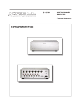
Figure 3 The S–1000 Back Panel
ANALOG AUDIO INPUTS
AND OUTPUTS
34 Balanced Analog
Audio Outputs
35 Single-ended
Analog Audio Outputs
36 Balanced Analog
Audio Inputs
37 Tape In Left and Right
38 Tape Out Left and Right
39 VCR In Left and Right
40 VCR Out Left and Right
41 Single-ended
Analog Audio Inputs
42 7.1 Audio Inputs
DIGITAL AUDIO
INPUTS AND OUTPUTS
43 Optical Digital Audio Inputs
44 Coaxial Digital Audio Inputs
45 Digital Audio Output
VIDEO INPUTS AND
OUTPUTS
46 S-video Outputs
47 S-video Inputs
48 Composite Video Outputs
49 Composite Video Inputs
50 Component Video Outputs
51 Component Video Inputs
52 HDMI
TM
Output
53 HDMI
TM
Inputs
BACK PANEL REMOTE
CONTROL CONNECTIONS
54 Comm Port RS-232
Remote Connector
55 RC-5 In
56 12 VDC In and Out
57 DB 25 Out
POWER
CONNECTIONS
58 Back Panel Power Switch
59 IEC Connector
14 Krell S–1000
BACK PANEL
FUNCTIONS

DEVICE S–1000 CONNECTIONS FACTORY DEFAULT DECODING MODES
Digital Analog Digital Analog
Video Audio Audio Dolby 2.0 Dolby 5.1 DTS 5.1 PCM
DVD Component 1 COAX 1 S1 Dolby D+ Dolby D 5.1 DTS 5.1 Dolby PLII Dolby PLII
Dolby PLII Movie Movie Movie Movie
CABLE HDMI
TM
2 COAX 3 S4 Dolby D+ Dolby D 5.1 DTS 5.1 Dolby PLII Dolby PLII
Dolby PLII Movie Movie Movie Movie
SAT HDMI
TM
1 OPT 1 S3 Dolby D+ Dolby D 5.1 DTS 5.1 Dolby PLII Dolby PLII
Dolby PLII Movie Movie Movie Movie
VCR S-Video 2 Disabled VCR N/A N/A N/A N/A Dolby PLII
Movie
TV Composite 1 COAX 2 S2 Dolby D+ N/A N/A N/A Dolby PLII
Dolby PLII Movie Movie
CD Disabled Disabled B1 N/A N/A N/A N/A Preamp
TUNER Disabled Disabled S5 N/A N/A N/A N/A Preamp
AUX Disabled Disabled 7.1 N/A N/A N/A N/A N/A
GAME Component 2 OPT 2 S6 N/A Dolby D 5.1 DTS 5.1 Dolby PLII Preamp
TAPE Composite 3 Disabled Tape N/A N/A N/A N/A Preamp
Krell S–1000 15
TABLE 1 S –1000 Connections and Corresponding
Factory Default Decoding Modes, by Device
Connect the S–1000 to the rest of the components in your system,
u
sing this table as a guide.
When the S–1000 is in the operating mode, press the mode button or M1
key (16) on the remote control to read the current processing mode in the
front panel display. Press the mode button or M2 key (17) to review and select
other available modes. See
Decoding Modes, on page 9.
In the menu mode,
Step 2, Configure Devices screens show available
decoding modes, by device. For example, see Assign Digital Audio
Inputs, on page 34; DTS Contr
ol,
on page 44; PLII Contr
ol
, on page 45.
The Appendix: Decoding Modes for the S–1000, on page 60, shows all
the decoding modes for the
S
–1000, and includes a listing of Kr
ell Music
Surround modes.
Notes

Back Panel Description
S
ee Figure 3 on page 14
16 Krell S–1000
The back panel of the S–1000 Surround Preamp/processor provides
all audio and video input and output connections, remote control
inputs and outputs, power on and off, and power connection. The
back panel functions are described below.
34 Balanced Analog Audio Outputs
The S–1000 is equipped with eight balanced analog audio chan-
nel outputs, with XLR connectors, for the left, center, subwoofer,
surround left, surround right, back left, and back right.
35
Single-ended Analog Audio Outputs
The S–1000 is equipped with eight single-ended analog audio
channel outputs, with RCA connectors, for the left, center, right,
subwoofer, surround left, surround right, back left, and back right.
36 Balanced Analog Audio Inputs
The S–1000 is equipped with one set of balanced inputs with
XLR connectors.
37 Tape In Left and Right
The S–1000 is equipped with one set of single-ended tape
inputs with RCA connectors.
38 Tape Out Left and Right
The S–1000 is equipped with one set of single-ended tape out-
puts with RCA connectors.
39 VCR In Left and Right
The S–1000 is equipped with one set of single-ended inputs
with RCA connectors, for a VCR audio source.
40 VCR Out Left and Right
The S–1000 is equipped with one set of single-ended outputs
with RCA connectors, for a VCR audio source.
41 Single-ended Analog Audio Inputs
The S–1000 is equipped with seven sets of single-ended inputs
with RCA connectors.
42 7.1 Audio Inputs
The S–1000 is equipped with eight single-ended 7.1 analog pass-
through inputs for multichannel SACD and DVD audio devices.
43 Optical Digital Audio Inputs
The S–1000 is equipped with four optical digital EIAJ inputs with
T
osLink connectors.
FUNCTIONS
Analog Audio Outputs
and Inputs
Digital Audio Inputs
and Outputs
/