Page is loading ...

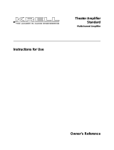
Showcase Processor
Surround
Preamp/Processor
Instructions for Use
Owner’s Reference
THE LEADER IN AUDIO ENGINEERING

Showcase Processor
Surround Preamp/Processor
Instructions for Use
v 02.3
Krell Industries, Inc.
45 Connair Road
Orange, CT 06477-3650 USA
TEL 203-799-9954
FAX 203-891-2028
E-MAIL [email protected]
WEBSITE http://www.krellonline.com
This product complies with the EMC directive (89/336/EEC) and the low-voltage
directive (73/23/EEC).
© 2002 by Krell Industries, Inc. All rights reserved P/N 306040
The Showcase Processor must be placed on a firm level surface where it is not
exposed to dripping or splashing.
The ventilation grids on the top and bottom of the Showcase Processor must be
unobstructed at all times during operation. Do not place flammable material above
or beneath the component.
Do not remove or bypass the ground pin on the end of the AC power cord. This
could cause radio frequency interference (RFI) to be introduced into your playback
system.
Before making connections to the Showcase Processor, make sure the back panel
power switch is off. Make sure all cable terminations are of the highest quality and
free from frayed ends, short circuits, or cold solder joints.
THERE ARE NO USER SERVICEABLE PARTS INSIDE ANY KRELL PRODUCT.
Please contact your authorized Krell dealer, distributor, or Krell if you have any
questions not addressed in this Owner’s Reference.
DTS Digital Surround ™ is a discrete 5.1 channel digital audio format available on CD, LD, and DVD soft-
ware which consequently cannot be decoded and played back inside most CD, LD, or DVD players. For this
reason, when DTS-encoded software is played back through the analog outputs of the CD, LD, or DVD play-
er, excessive noise will be exhibited. To avoid possible damage to the audio system, proper precautions
should be taken by the consumer if the analog outputs are connected directly to an amplification system. To
enjoy DTS Digital Surround ™ playback, an external 5.1 channel DTS Digital Surround ™ decoder system
must be connected to the digital output (S/PDIF, AES/EBU, or TosLink) of the CD, LD, or DVD player.
This product is manufactured in the United States of America. Krell
®
is a registered trademark of Krell
Industries, Inc., and is restricted for use by Krell Industries, Inc., its subsidiaries, and authorized agents. Krell
Smart System Setup™ is a trademark of Krell Industries, Inc. “DTS”, “DTS Digital Surround”, “DTS ES
Extended Surround”, and “Neo:6” are registered trademarks of Digital Theater Systems, Inc. TosLink is a
trademark of Toshiba Corporation. Manufactured under license from Dolby Laboratories. "Dolby," "Pro
Logic," and the double-D symbol are trademarks of Dolby Laboratories. Confidential Unpublished Works.
Copyright 1992–1997 Dolby Laboratories, Inc. All rights reserved. THX is a registered trademark of
Lucasfilm, Ltd. Re-Equalization, Timbre Matching, and Decorrelation are trademarks of Lucasfilm, Ltd. All
other trademarks and trade names are registered to their respective companies.
CONTACT
INFORMATION
WARNINGS

Contents
Krell Showcase Processor iii
INTRODUCTION 1
DEFINITION OF TERMS 2
UNPACKING 4
PLACEMENT 5
AC Power Guidelines 5
GETTING STARTED 6
Please Read This First 6
To Select the Initial Video Signal and Format 9
An Introduction to System Setup 10
FRONT PANEL DESCRIPTION 12
BACK PANEL DESCRIPTION 18
REMOTE CONTROL DESCRIPTION 22
Battery Installation and Removal 22
CONNECTING THE SHOWCASE PROCESSOR
TO YOUR SYSTEM 27
First: Connect Analog and Digital Sources 27
Next: Connect Video Sources 28
Last: Connect Amplifiers and Sources 28
OVERVIEW: SYSTEM CONFIGURATION AND NAVIGATION 30
Configuration Steps 30
Navigation Conventions 31
SYSTEM CONFIGURATION 32
Accessing the Main Menu 32
Step 1: Configure Loudspeakers 33
Step 2: Listening Room Setup 35
Step 3: Calibrate Volume 36
Step 4: Configure Devices 38
Step 5: Configure Level Adjustment 47
Step 6: Operation 55
SAVING AND RECALLING CUSTOMIZED SETTINGS AND
RESTORING THE FACTORY DEFAULT SYSTEM SETTINGS 67
OPERATING THE SHOWCASE PROCESSOR 68
On/Off/Stand-by, Tape Input and Output 68
Simulcast 69
APPENDIX: OPERATING MODES FOR
THE SHOWCASE PROCESSOR 70
Automatically Detected Modes 70
User Selectable Modes 71
WARRANTY 74
RETURN AUTHORIZATION PROCEDURE 75
SPECIFICATIONS 76-77
Page

iv Krell Showcase Processor
FIGURE 1 Front Panel Input Device Selection Buttons
and Associated Factory Default Video Signals
and Video Formats for North American
Operation of the Showcase Processor 7
FIGURE 2 Front Panel Input Device Selection Buttons
and Associated Factory Default Video Signals
and Video Formats for International Operation
of the Showcase Processor 8
FIGURE 3 The Showcase Processor Front Panel 11
FIGURE 4 The Showcase Processor Back Panel 17
FIGURE 5 The Showcase Processor
Remote Control 21
TABLE 1 Video Signals and Video Formats Supported
by the Showcase Processor 6
TABLE 2 Factory Default Video Inputs and Standards for
the Showcase Processor, North American Operation 39
TABLE 3 Factory Default Video Inputs and Standards for the
Showcase Processor, International Operation 39
TABLE 4 Factory Default Digital and Analog Inputs for the
Showcase Processor, North American and International
Operation 41
TABLE 5 Showcase Processor
Audio Operating Modes 42
TABLE 6 Krell Music Surround Modes for the
Showcase Processor 73
Illustrations
Tables
Page
Page

Krell Showcase Processor 1
Thank you for your purchase of the Krell Showcase Processor.
The Showcase Processor serves as the centerpiece in a Krell
HEAT™—High End Audio Theater—system, which applies the
fundamental principles of Krell engineering to the creation of a fully
integrated high-performance multichannel sound system. The
Showcase Processor delivers unparalleled music and cinema sound-
track reproduction through the use of a full complement of advanced
Krell technologies including Smart System Setup, discrete Class A,
direct-coupled circuitry with balanced outputs, user-configurable input
assignment, and broadcast-quality video circuitry.
The Showcase Processor is THX Ultra certified and features THX
Surround EX, Dolby Digital 5.1, Dolby Digital EX, DTS-ES 6.1, DTS
NEO:6, and Dolby Pro Logic II processing, in addition to nine propri-
etary Krell Music Surround modes. This flexibility allows upgrades to
software via Flash memory for future surround sound formats and
design enhancements.
The owner’s reference manual contains important information on
placement, installation, and operation of the Krell Showcase
Processor. Please read this information carefully. A thorough under-
standing of these details helps ensure satisfactory operation of
and long life for your Showcase Processor and related system com-
ponents.
Introduction

2 Krell Showcase Processor
Following are the definitions of key terms used in your owner’s refer-
ence manual:
Balanced
A symmetrical input or output circuit that has equal impedance from
both input terminals to a common ground reference point. The indus-
try standard for professional and sound recording installations, bal-
anced connections have 6 dB more gain than single-ended connec-
tions and allow the use of long interconnect cables. Balanced con-
nections are immune to induced noise from the system or the envi-
ronment.
Single-ended
A two-wire input or output circuit. Use care when using single-ended
connections as the ground connection is made last and broken first.
Turn the system off prior to making or breaking single-ended connec-
tions. Single-ended connections are not recommended for connec-
tions requiring long cable runs.
Off
When the power switch on the back panel is placed in the down
position and LEDs turn off, the component is off.
Stand-by Mode
When the Showcase Processor is connected to AC power and the
back panel power switch is in the up (on) position, the red stand-by
LED illuminates. This indicates that the component is in stand-by
mode, a low power consumption status that keeps the audio and reg-
ulator circuits at idle. Krell recommends leaving the component in the
stand-by mode when it is not playing music.
Operational Mode
When the component is in the stand-by mode, and you press the
power button on the front panel or the power key on the remote
control, the blue power LED illuminates. The component is in the
operational mode and is ready to play music.
Definition of Terms
INPUT AND OUTPUT
CONNECTIONS
OPERATION

Krell Showcase Processor 3
Krell HEAT
The Krell term HEAT, or High End Audio Theater, is a design applica-
tion incorporated into Krell components to enhance multichannel
home entertainment systems. A Krell HEAT system is an integrated
home theater system consisting of a state-of-the-art Krell
preamp/processor and matching amplifiers that reproduce two chan-
nel and multichannel sources with audiophile sound quality, placing
the audience in the middle of a lifelike environment.
Composite Video
An encoded video signal that transmits luminance (Y) and color (C)
information on one wire.
S-Video
Video signal that separately transmits the luminance (Y) and color
(C) components of the video signal using one wire.
Component Video
A video signal that uses three wires to convey luminance (Y), red
minus luminance (R-Y), and blue minus luminance (B-Y) signals.
Component video signals may be interlaced or progressive.
Progressive signals build screen content in one pass rather than the
two passes required for standard (interlaced) video. Progressive
technology eliminates motion artifacts and produces film-quality pic-
tures. Both your source and video monitor must be equipped with
progressive video technology to realize this advantage.
YPbPr
One way of designating color difference signals. Y = the luminance
signal, Pb = the blue minus luminance (B-Y) signal, and Pr = the red
minus luminance (R-Y) signal.
Definition of Terms, continued
TECHNOLOGY
VIDEO

Unpacking
4 Krell Showcase Processor
Open the box and remove the top layer of foam. You see these
items:
1 Showcase Processor
1 IEC connector (AC power) cord
1 Showcase Processor handheld remote control
1 CR2025 lithium battery
1 12 VDC output (12 V trigger) cable
1 packet containing the owner’s reference manual
and the warranty registration card.
Carefully remove the Showcase Processor and accessories from the
box. Remove the foam end caps and protective plastic wrap from the
component.
If any of these items are not included in the shipping box, please contact
your authorized Krell dealer, distributor, or Krell for assistance. Save all
packing materials. If you must ship your Showcase Processor in the future,
repack the unit in its original packaging to prevent damage in transit. See
Return Authorization Procedure, on page 75.
Note

Krell Showcase Processor 5
Before you install the Showcase Processor into your system, review
the following guidelines to choose the location for the component.
This will facilitate a clean, trouble-free installation.
The Showcase Processor does not require any type of special rack
or cabinet for installation. For the dimensions of your Showcase
Processor see Specifications, on pages 76-77.
The Showcase Processor requires at least two inches (5 cm) of
clearance on each side and at least two inches (5 cm) of clearance
above and below the component to provide adequate ventilation. In
addition, the Showcase Processor requires at least three inches
(7 cm) of clearance between other connected components. For
installations inside cabinetry, extra ventilation may be necessary.
The Showcase Processor has superb regulation and does not
require a dedicated AC circuit. Avoid connections through extension
cords or multiple AC adapters. High quality 15 amp grounded AC
strips are acceptable.
High quality AC line conditioners or filters may be used if they are
grounded and meet or exceed the unit’s power supply rating of 100
VA. Contact your authorized Krell dealer, distributor, or Krell before
using any devices designed to alter or stabilize the AC power for the
Showcase Processor.
The Showcase Processor should be used only with the power cord
supplied.
Placement
AC POWER
GUIDELINES

Getting Started
6 Krell Showcase Processor
The video formats and video signals of the Showcase Processor
need to match the video monitor, for the on-screen display (OSD) to
be viewable on your video monitor. The format of the video signal
can be set to either of two standards: NTSC or PAL. See Table 1
and Figures 1 and 2 below.
First match the device with the appropriate factory default to your
video monitor’s format, NTSC or PAL, and match it to the video sig-
nal used to connect the Showcase Processor to your video monitor.
The device must be active in order for both the OSD information and
the menu to be visible.
North American Example
Select the DVD device to an NTSC video monitor and use the com-
ponent video output to connect the Showcase Processor to your
monitor.
International Example
Select the VCR device to a PAL video monitor and use the
S-Video OSD output to connect the Showcase Processor to your
monitor.
Table 1 Video Signals and Video Formats Supported
by the Showcase Processor
PLEASE READ
THIS FIRST
Commonly
Labeled
Video
Signal
Composite
S-Video
Component
Video, Composite
S, SV, S-Video
Y, Pr, Pb
Connector
Used
Single-ended RCA
DIN
3 Single-ended RCA
Video
Signal
NTSC or PAL
NTSC or PAL
NTSC or PAL

Krell Showcase Processor 7
Getting Started, continued
Composite 3 (TAPE)
NTSC Interlaced
Component 1
NTSC Interlaced
SIGNAL
FORMAT
S-Video 2
NTSC Interlaced
Composite 1
NTSC Interlaced
S-Video 1
NTSC Interlaced
Composite 2
NTSC Interlaced
Figure 1 Front Panel Input Device Selection Buttons and
Associated Factory Default Video Signals and Video Formats,
for North American Operation of the Showcase Processor
Note
For CD, TUNER, AUX, and
GAME, the factory video
defaults are disabled and
therefore a video format
is not available.

8 Krell Showcase Processor
Getting Started, continued
Composite 3 (TAPE)
NTSC Interlaced
Component 1
NTSC Interlaced
SIGNAL
FORMAT
S-Video 2
PAL Interlaced
Composite 1
NTSC Interlaced
S-Video 1
NTSC Interlaced
Component 2
PAL Interlaced
Composite 2
PAL Interlaced
Figure 2 Front Panel Input Device Selection Buttons and
Associated Factory Default Video Signals and Video Formats,
for International Operation of the Showcase Processor
Note
For CD, TUNER, AUX, and
GAME, the factory video
defaults are disabled and
therefore a video format
is not available.

Krell Showcase Processor 9
Getting Started, continued
1. Connect your video monitor to the video output connectors on
the Showcase Processor that correspond to the input connectors
on your video monitor. See Table 1, on page 6.
2. Power on the Showcase Processor by switching the back panel
power switch to on. Wait for the Showcase Processor to initialize.
Then press the power button on the front panel.
3. Press the front panel input device selection button that matches
both the video format and video signal compatible with your con-
nected video monitor. See Figure 1 for North American operation
and Figure 2 for International operation. This becomes the cur-
rently selected video signal output.
4. Verify that the video monitor’s video signal input corresponds to
the Showcase Processor video signal output. Press the menu
key on the remote control to verify that the OSD is now viewable
on the video monitor. The system configuration main menu
appears when the video format and video signals between the
Showcase Processor and your video monitor are compatible.
If you have any questions regarding the selection of the video format,
please call your authorized Krell dealer, distributor, or Krell.
TO SELECT THE INITIAL
VIDEO SIGNAL AND
FORMAT

10 Krell Showcase Processor
Getting Started, continued
The Showcase Processor provides a variety of connection and oper-
ation options for outstanding music and cinema soundtrack reproduc-
tion. To take full advantage of the features the Showcase Processor
offers, you’ll need to set up your system in this order:
1. Connect your Showcase Processor to the desired analog and
digital audio sources, video sources, and amplifiers. See
Connecting the Showcase Processor to Your System, on
page 27.
2. Configure the loudspeakers, input devices, and trims using the
built-in, easy-to-follow system configuration menus. Step-by-step
instructions begin on page 32, System Configuration.
3. Review the front panel, back panel, and remote control descrip-
tions for information on input, and mode selections, loudspeaker
adjustment, input and output connections for analog, digital, and
video sources, and remote control operation. See pages 11-27
for illustrations and descriptions.
After you’ve connected and configured your Showcase Processor
and know its basic features, you’re ready to go. See Operating the
Showcase Processor, on page 68.
AN INTRODUCTION
TO SYSTEM SETUP

11 CD Button
12 Tuner Button
13 Aux Button
14 Game Button
15 Tape/VCR2 Button
Processing Mode Buttons
and LEDs
16 Stereo Button and LED
17 Mode 1 Button and LED
18 Mode 2 Button and LED
19 Pro Logic II Button and LED
20 Preamp Button and LED
21 THX Button
Basic Operation
1 Power Button
2 Power LED
3 Stand-by LED
4 Infrared Sensor
5 Infrared Emitter
Input Device
Selection Buttons
6 DVD Button
7 LD Button
8 SAT Button
9 VCR Button
10 TV Button
Display
22 Front Panel Display
Individual Channel
Trim Buttons
23 Center Button
24 Surr/Back Button
25 Sub Button
26 Balance Button
Processor Function
Buttons
27 Save Button
28 Direction or Level Buttons
29 Recall Button
Figure 3 The Showcase Processor Front Panel
SHOWCASE
PROCESSOR
GAME
VCR TV
TAPE/VCR2
DVD
LD
SAT
CD
TUNER
AUX
STAND-BY
POWER
RECALL
SAVE LEVEL
THX
BALANCE
CENTER SURR/BACK
SUB
PRE AMP STEREO
MODE 1
MODE 2
PRO LOGIC II
611 712 813 9 10 20 16 17 18 1914 15
21 26 23 28 24 252729 2254123

Front Panel Description
See Figure 3 on page 11
12 Krell Showcase Processor
The Showcase Processor front panel provides power on and off;
input, and processing mode selection; monitoring and display of
processor status; and balance and volume control. The front panel
features are described below:
1 Power Button
The power button switches the Showcase Processor from stand-by
to the operational mode.
2 Power LED
The blue power LED illuminates when the Showcase Processor is in
the operational mode.
3 Stand-by LED
The red stand-by LED illuminates when the back panel power switch
(51) is on, indicating that the Showcase Processor is in the stand-by
mode. Krell recommends that the back panel power switch remain
on at all times.
4 Infrared Sensor
The infrared sensor receives commands from the Showcase
Processor remote control. For proper remote control operation, make
sure the infrared sensor is not covered or obstructed.
5 Infrared Emitter
Emits the Showcase Processor remote operation code to a learning
remote. See Program Remote, on page 61.
The Showcase Processor is equipped with ten input device selection
buttons. If properly configured, the Showcase Processor automatically
engages the correct video and audio inputs when you press the
device selection button.
6 DVD Button
Use this button to select the digital videodisc device.
7 LD Button
Use this button to select the laser disc device.
8 SAT Button
Use this button to select the satellite feed device.
Basic Operation
Buttons
FEATURES
Input Device Selection
Buttons and LEDs

Krell Showcase Processor 13
9 VCR Button
Use this button to select the VCR device.
10 TV Button
Use this button to select the television device.
11 CD Button
Use this button to select the compact disc device.
12 Tuner Button
Use this button to select the AM/FM tuner device.
13 Aux Button
Use this button to select an auxiliary device, such as phono, tape, or
an additional DVD, LD, CD, or VCR.
14 Game Button
Use this button to select a game.
15 Tape/VCR2 Button
Use this button to playback pre-recorded tapes. You may also use
this button to compare the output signal of an analog tape recorder to
an audio source. See Tape Input and Output, on page 68.
Front Panel Description, continued
Input Device Selection
Buttons and LEDs,
continued

Front Panel Description, continued
14 Krell Showcase Processor
16 Stereo Button and LED
Use this button to select stereo decoding, which allows you to make
an A/B comparison or listen to a stereo recording in two channel for-
mat (left and right). The red LED illuminates when this feature is
engaged.
After you select a mode, press the stereo button once. Press the
stereo button again to make the A/B comparison. Press the stereo
button again to exit stereo format.
You can make an A/B comparison when you press the stereo button, only if
you have selected a previous mode.
17 Mode 1 Button and LED
18 Mode 2 Button and LED
Use these buttons to select available processing modes (such as
Dolby Digital, DTS, PLII Movie, THX, etc.) for incoming signals from
a video or audio source.
The default mode for a signal is always stored in Mode 1. Use the
Mode 1 button to select the default mode. All modes that can be
used for the same signal are automatically stored in Mode 2. Use the
Mode 2 button to scroll through these other modes. The last mode
displayed in Mode 2 is the one selected. Based on the source signal,
the Showcase Processor automatically selects the correct modes
available for the signal.
19 Pro Logic II Button and LED
Use this button to select the Dolby Pro Logic II modes for Dolby
Surround encoded material, including laser discs, videotapes, televi-
sion broadcasts, and compact discs. The red LED illuminates when
Dolby Pro Logic II decoding is selected.
These modes are selected automatically if Dolby Digital source material is
encoded for Pro Logic. To turn off these modes, press the Pro Logic II but-
ton.
Processing Mode
Buttons and LEDs
Note
Note

Krell Showcase Processor 15
20 Preamp Button and LED
Use this button to send the signal from an analog input directly to the
volume control, with no digital processing, using the analog stage of
the preamp. This avoids possible digital signal degradation and can
be used for components such as the Krell KPS 28c Compact Disc
Player that have a high quality signal. See Assign Analog Audio
Inputs, on page 43, for information on assigning the analog input to
one of the device buttons (DVD, LD, SAT, VCR, TV).
This feature is only available with a signal from an analog input. If you
attempt to use it with a signal from a digital input, The Showcase Processor
on-screen display will read NOT ALLOWED.
21 THX Button
Use this button to select one of the various THX modes available for
the current signal.
Front Panel Description, continued
Display
Processing Mode Buttons
and LEDs,
continued
22 Front Panel Display
The front panel window provides status messages for Showcase
Processor operations, including volume and balance level, decoding
mode and zone information. In addition, when a new device is
selected, the physical inputs are displayed. The display turns off after
60 seconds of inactivity.
Note
Individual Channel
Trim Buttons
Use the center, surr/back, and sub buttons to change taste trims (to
make temporary speaker output adjustments) of +/- 10 dB. These
temporary changes revert to 0 dB when a new device is selected or
when the system is powered down. For more information on taste
trims and master (programmable) trims, see Configure Level
Adjustment, on page 47.
23 Center Button
Press the center button, then use the direction or level buttons (28) to
adjust the center loudspeaker volume.
24 Surr/Back Button
Press the surr/back button, then use the direction or level buttons
(28) to adjust the volume of the surround loudspeakers. To adjust the
back loudspeakers, press the surr/back button.
SURROUND TRIM
appears on the front panel display. Press the surr/back button again.
BACK appears on the front panel display. Then use the direction or
level buttons to adjust the volume of the back loudspeakers.

Front Panel Description, continued
16 Krell Showcase Processor
Individual Channel
Trim Buttons
continued
25 Sub Button
Press the sub (subwoofer) button, then use the direction or level but-
tons (28) to adjust the subwoofer loudspeaker volume.
26 Balance Button
Press this button to adjust the main left/right speaker balance. This
button converts the volume level controls to balance controls.
Balance levels are shown numerically on the front panel display.
Balance may be adjusted in .5 dB increments, up to 6 dB. The center
position is displayed as
BAL 0. The balance level buttons revert back
to their original functions as volume level controls after 3 seconds of
inactivity.
27 Save Button
Press and hold this button to save system configuration settings. The
save button is also used in programming a learning remote. See
Saving and Recalling Customized Settings and Restoring the
Factory Default System Settings, on page 67, and Program
Remote, on page 61.
28 Direction or Level Buttons
Use these buttons to scroll through menu selections, adjust the out-
put for the entire system, and adjust balance and volume levels for
the center loudspeaker, surround/back loudspeakers, and subwoofer.
In the operational mode, right button engages Digital Room EQ and
the up and down buttons select EQ memory. Volume and balance
levels are shown in the front panel display (22).
29 Recall Button
Use this button to recall previously stored system configuration set-
tings. Also use this button to return configuration settings to factory
default: With the Showcase Processor in the operational mode, hold
the recall button and press the power button. See Saving and
Recalling Customized Settings and Restoring the Factory
Default System Settings, on page 67.
Processor Function
Buttons
/