Page is loading ...

INSTRUCTION MANUAL
N2151/N2251 ENCODERS/DECODERS
4K DIGITAL MEDIA DISTRIBUTION & SWITCHING SOLUTION
NMX-ENC-N2151, NMX-DEC-N2251

IMPORTANT SAFETY INSTRUCTIONS
COPYRIGHT NOTICE
AMX© 2016, all rights reserved. No part of this publication may be reproduced, stored in a retrieval system, or transmitted, in any form or by any
means, electronic, mechanical, photocopying, recording, or otherwise, without the prior written permission of AMX. Copyright protection claimed
extends to AMX hardware and software and includes all forms and matters copyrightable material and information now allowed by statutory or judicial
law or herein after granted, including without limitation, material generated from the software programs which are displayed on the screen such as
icons, screen display looks, etc. Reproduction or disassembly of embodied computer programs or algorithms is expressly prohibited.
LIABILITY NOTICE
No patent liability is assumed with respect to the use of information contained herein. While every precaution has been taken in the preparation of this
publication, AMX assumes no responsibility for error or omissions. No liability is assumed for damages resulting from the use of the information
contained herein. Further, this publication and features described herein are subject to change without notice.
AMX WARRANTY AND RETURN POLICY
The AMX Warranty and Return Policy and related documents can be viewed/downloaded at www.amx.com.
1. READ these instructions.
2. KEEP these instructions.
3. HEED all warnings.
4. FOLLOW all instructions.
5. DO NOT use this apparatus near water.
6. CLEAN ONLY with dry cloth.
7. DO NOT block any ventilation openings. Install in accordance with the manufacturer's instructions.
8. DO NOT install near any heat sources such as radiators, heat registers, stoves, or other apparatus (including amplifiers) that
produce heat.
9. DO NOT defeat the safety purpose of the polarized or grounding type plug. A polarized plug has two blades with one wider than the
other. A grounding type plug has two blades and a third grounding prong. The wider blade or the third prong are provided for your
safety. If the provided plug does not fit into your outlet, consult an electrician for replacement of the obsolete outlet.
10. PROTECT the power cord from being walked on or pinched, particularly at plugs, convenience receptacles, and the point where
they exit from the apparatus.
11. ONLY USE attachments/accessories specified by the manufacturer.
12. UNPLUG this apparatus during lightning storms or when unused for long periods of time.
13. REFER all servicing to qualified service personnel. Servicing is required when the apparatus has been damaged in any way, such as
power-supply cord or plug is damaged, liquid has been spilled or objects have fallen into the apparatus, the apparatus has been
exposed to rain or moisture, does not operate normally, or has been dropped.
14. DO NOT expose this apparatus to dripping or splashing and ensure that no objects filled with liquids, such as vases, are placed on
the apparatus.
15. To completely disconnect this apparatus from the AC Mains, disconnect the power supply cord plug from the AC receptacle.
16. Where the mains plug or an appliance coupler is used as the disconnect device, the disconnect device shall remain readily operable.
17. DO NOT overload wall outlets or extension cords beyond their rated capacity as this can cause electric shock or fire.
The exclamation point, within an equilateral triangle, is intended to alert the user to the presence of important operating and maintenance
(servicing) instructions in the literature accompanying the product.
The lightning flash with arrowhead symbol within an equilateral triangle is intended to alert the user to the presence of uninsulated “dangerous
voltage” within the product's enclosure that may be of sufficient magnitude to constitute a risk of electrical shock to persons.
ESD Warning: The icon to the left indicates text regarding potential danger associated with the discharge of static electricity from an outside
source (such as human hands) into an integrated circuit, often resulting in damage to the circuit.
WARNING: To reduce the risk of fire or electrical shock, do not expose this apparatus to rain or moisture.
WARNING: No naked flame sources - such as candles - should be placed on the product.
WARNING: Equipment shall be connected to a MAINS socket outlet with a protective earthing connection.
WARNING: To reduce the risk of electric shock, grounding of the center pin of this plug must be maintained.

3
N2151/N2251 User Manual
ESD WARNING
WARNING: This product is intended to be operated ONLY from the voltages listed on the back panel or the recommended, or
included, power supply of the product. Operation from other voltages other than those indicated may cause irreversible
damage to the product and void the products warranty. The use of AC Plug Adapters is cautioned because it can allow the
product to be plugged into voltages in which the product was not designed to operate. If the product is equipped with a
detachable power cord, use only the type provided with your product or by your local distributor and/or retailer. If you are
unsure of the correct operational voltage, please contact your local distributor and/or retailer.
FCC AND CANADA EMC COMPLIANCE INFORMATION:
This device complies with part 15 of the FCC Rules. Operation is subject to the following two conditions:
(1) This device may not cause harmful interference, and (2) this device must accept any interference received, including
interference that may cause undesired operation.
NOTE: This equipment has been tested and found to comply with the limits for a Class A digital device, pursuant to part 15 of
the FCC Rules. These limits are designed to provide reasonable protection against harmful interference in a residential
installation. This equipment generates, uses and can radiate radio frequency energy and, if not installed and used in
accordance with the instructions, may cause harmful interference to radio communications. However, there is no guarantee
that interference will not occur in a particular installation. If this equipment does cause harmful interference to radio or
television reception, which can be determined by turning the equipment off and on, the user is encouraged to try to correct
the interference by one or more of the following measures:
•Reorient or relocate the receiving antenna.
•Increase the separation between the equipment and receiver.
•Connect the equipment into an outlet on a circuit different from that to which the receiver is connected.
•Consult the dealer or an experienced radio/TV technician for help.
Approved under the verification provision of FCC Part 15 as a Class A Digital Device.
Caution: Changes or modifications not expressly approved by the manufacturer could void the user's authority to operate this
device.
CAN ICES-3 (B)/NMB-3(B)
EU COMPLIANCE INFORMATION:
Eligible to bear the CE mark; Conforms to European Union Low Voltage Directive 2006/95/EC; European Union EMC Directive
2004/108/EC; European Union Restriction of Hazardous Substances Recast (RoHS2) Directive 2011/65/EU.
You may obtain a free copy of the Declaration of Conformity by visiting http://www.amx.com/techcenter/certifications.asp.
WEEE NOTICE:
To avoid ESD (Electrostatic Discharge) damage to sensitive components, make sure you are properly grounded before
touching any internal materials.
When working with any equipment manufactured with electronic devices, proper ESD grounding procedures must be
followed to make sure people, products, and tools are as free of static charges as possible. Grounding straps, conductive
smocks, and conductive work mats are specifically designed for this purpose.
Anyone performing field maintenance on AMX equipment should use an appropriate ESD field service kit complete with at
least a dissipative work mat with a ground cord and a UL listed adjustable wrist strap with another ground cord
WARNING: Do Not Open! Risk of Electrical Shock. Voltages in this equipment are
hazardous to life. No user-serviceable parts inside. Refer all servicing to qualified
service personnel.
Place the equipment near a main power supply outlet and make sure that you can
easily access the power breaker switch.
This appliance is labeled in accordance with European Directive 2012/19/EU concerning waste of electrical and electronic
equipment (WEEE). This label indicates that this product should not be disposed of with household waste. It should be
deposited at an appropriate facility to enable recovery and recycling.

Table o f Conte nts
4
N2151/N2251 User Manual
Table of Contents
Introducing Your New N2151/N2251 4K Devices ............................................6
Product Overview .............................................................................................................. 6
Hardware Overview ........................................................................................................... 6
Installing and Configuring Your AV Equipment ................................................9
Installation Overview ........................................................................................................ 9
Mounting Options ........................................................................................................... 10
Surface and Wall Mounting................................................................................................................... 10
Rack Mounting ...................................................................................................................................... 10
N2X51 Series Stand-Alone Units ...................................................................................................... 10
N2X51 Series Cards .......................................................................................................................... 10
Step-by-Step Installation Instructions .......................................................................... 12
How IP Address Changes Affect Unit Control ...................................................................................... 17
Changing IP Addresses ........................................................................................................................ 18
Option 1: Assigning IP Addresses Individually (using the Settings page) .......................................... 18
Option 2: Assigning IP Addresses to Multiple Units (using CSV files) ................................................. 18
Switching and Scaling Options....................................................................................... 20
Seamless Switching .............................................................................................................................. 20
Control Options .............................................................................................................. 21
Primary Control Options ....................................................................................................................... 21
N-Command Controllers ....................................................................................................................... 21
Third-Party Controllers......................................................................................................................... 21
N-Act | On-Board, Built-In Control ....................................................................................................... 21
N-Touch | IP Wall Controller................................................................................................................. 21
KVM Configuration........................................................................................................... 22
Basic Setup ........................................................................................................................................... 22
Video/USB Switching Options........................................................................................................... 22
Advanced KVM Setup (With Added Security Features)........................................................................ 22
Encoder Configuration Options .......................................................................24
Settings Page .................................................................................................................. 25
Encoder Setup Section .................................................................................................... 26
Advanced Settings........................................................................................................... 28
RS232 Settings ............................................................................................................... 30
Network Setup Section................................................................................................... 30
Status Section ................................................................................................................ 31
Change Password Section............................................................................................... 32
Software Section ............................................................................................................. 32
HDMI Pass Thru Settings Section.................................................................................... 33
HostPlay Page................................................................................................................. 34

Table o f Conte nts
5
N2151/N2251 User Manual
IR Page ............................................................................................................................ 35
N-Act Page....................................................................................................................... 36
Serial Page...................................................................................................................... 37
Security Page .................................................................................................................. 38
KVM Page......................................................................................................................... 39
EDID Page ....................................................................................................................... 40
Logs Page ....................................................................................................................... 41
LLDP Page ....................................................................................................................... 41
Decoder Configuration Options .......................................................................42
Settings Page ................................................................................................................. 43
Decoder Setup Section ................................................................................................... 44
Advanced Settings.......................................................................................................... 46
RS232 Settings ............................................................................................................... 48
Network Setup Section................................................................................................... 48
Status Section ................................................................................................................ 49
Change Password Section.............................................................................................. 50
Software Section ............................................................................................................ 50
Audio Downmixer Settings ............................................................................................. 51
LocalPlay Page................................................................................................................. 53
IR Page ........................................................................................................................... 54
N-Act Page....................................................................................................................... 55
Serial Page....................................................................................................................... 56
Security Page ................................................................................................................. 57
KVM Page......................................................................................................................... 58
EDID Page ........................................................................................................................ 59
Logs Page ....................................................................................................................... 60
LLDP Page ....................................................................................................................... 60
Troubleshooting ..............................................................................................61
Series Default Local/Host Play Troubleshooting Screens .............................................. 62
Appendix A: Minimum Network Requirements ...............................................65

Introducing Your New N2151/N2251 4K Devices
6
N2151/N2251 User Manual
Chapter 1: Introducing Your New N2151/N2251 4K Devices
Product Overview
The NMX-ENC-N2151 4K Encoder and NMX-DEC-N2251 4K Decoder provide users with the industry's most versatile solution for
distributing AV over a converged network at resolutions up to 4096×2160. JPEG2000 compression allows Ultra HD media to be
switched and distributed over standard Gigabit Ethernet networks. Ultra HD signals from the NMX-ENC-N2151 Encoder are
provided simultaneously as: 1) a JPEG2000-compressed 200-600 Mbps stream through the RJ45 connector or small-form-
pluggable (SFP+) port (10Gb), and 2) an uncompressed stream through the SFP+ connector (via a fiber module). Any source can
be sent to any number of displays by routing through managed switches. System scalability is limited only by uplink and stacking
connector bandwidths.
Standard features like output scaling (Decoder), bi-directional serial, IR output, embedded 7.1 audio, and KVM-over-IP extension
are included. The NMX-ENC-N2151-C and NMX-DEC-N2251-C form-factors are compatible with the NMX-ACC-N9206 card cage for
high-density applications.
The NMX-ENC-N2151 and NMX-DEC-N2251 together create the perfect solution for video matrix applications where resolutions up
to 4K are required. Common applications include classrooms, conference rooms, performing arts centers, and sports bars.
Features include:
Output Scaling — Video scaling at the output (Decoder) allows seamless switching from any source, at any resolution, to
any display or projector, while preserving video f idelity.
Infrared (IR) — Infrared emitter connection allows control of low-cost, IR-only display devices.
Onboard Control — All N-Series Encoders and Decoders have on-board, built-in control capability via events that can
trigger any number of TCP/UDP commands to other IP controllable devices.
Pass-through HDMI interface (Encoder) — allows easy installation with local display such as desktop PC applications.
Unlimited Scalability — Grow the video matrix by adding Encoders or Decoders as needed (within the bandwidth limits of
the uplink and stacking connectors).
Stand Alone or Card — Available as a stand alone device, or card for use with NMX-ACC-N9206.
Hardware Overview
Refer to the following figures (front and rear panel drawings of these devices) and the Front and Rear Panel Descriptions table on
page 7 for hardware details.
FIG. 1
Encoder Front Panel
FIG. 2 Encoder Rear Panel
3 4 51 2
1) USB Mini-B Port
2) USB Standard-A Ports (inactive on Encoders)
3) Device Reset Button
4) Device ID Discovery Button
5) Power/Status Indicators
9
1) 12VDC Input
2) Status Indicators
3) RJ45 Auto-Sensing Gigabit Ethernet Switch Port
4) 10G SFP+ Port
5) IR Emitter Connection
6) RS232 Connection
7) Analog Audio Input
8) Passthru HDMI Video
9) HDMI Video Input
10) DB-15 Analog Input
1 2 3 87654
10

Introducing Your New N2151/N2251 4K Devices
7
N2151/N2251 User Manual
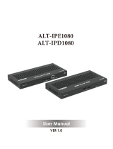
FIG. 3 Decoder Front Panel
FIG. 4 Decoder Rear Panel
1
2
3 54
1) USB Mini-B Port (inactive on Decoders)
2) USB Standard-A Ports
3) Device Reset Button
4) Device ID Discovery Button
5) Power/Status Indicators
1) 12VDC Input
2) Status Indicators
3) RJ45 Auto-Sensing Gigabit Ethernet Switch Port
4) 10G SFP+ Port
5) IR Emitter Connection
6) RS232 Connection
7) Analog Audio Input
8) HDMI Video Output
1 2 3 87654
Front and Rear Panel Descriptions
Front Panel
USB Mini-B port Connects the Encoder to the computer to be controlled.
USB Standard-A port (x2) Connects the Decoder to keyboard and/or mouse or touchscreen.
RESET button Recessed pushbutton. Press to initiate a “warm restart” which causes the processor to reset, but not lose
power. A reset does NOT affect the current settings.
ID button Recessed pushbutton. Press to send notification out on the network to identify the unit (the notification
causes a pop-up dialog in N-Able and N-Command). Press and hold for 30 seconds to initiate a factory
restore.
POWER LED On solid (green) when operating power is supplied (via local power supply). This activity is also shown by
the PWR LED on the rear panel.
STATUS LED On flashing (green) when there is software activity. This activity is also shown by the STAT LED on the rear
panel.
Rear Panel
+12V 2A 12 Volt DC power input.
PWR LED Same as POWER LED described above.
HDMI LED On (green) when an HDMI connection is present.
STAT LED Same as STATUS LED described above.
STRM LED On (green) when the unit is streaming video.
P0 8-wire RJ45 female.
10/100/1000 Mbps 10/100/1000Base-T auto-sensing gigabit Ethernet switch port.
Provides network connection to the Encoders and Decoders.
P1 10G SFP+ port which accepts compatible fiber transceivers or direct attach cables (copper or fiber).
Modules sold separately.
NOTE: This port does not accept 1G fiber. It supports 10G only. Multi-mode and single mode fiber options
are available.
IR 2-pin terminal Phoenix connector which provides IR output (33 to 60 kHz). Emitter is not included.
RS232 3-pin terminal Phoenix connector which provides a serial control interface. Full duplex communication.
Available terminal speed settings: 1200 to 115200 baud rate.

Introducing Your New N2151/N2251 4K Devices
8
N2151/N2251 User Manual
AUDIO 5-pin terminal Phoenix connector which provides user-selectable balanced/unbalanced, dedicated audio
input (for Encoders) and output (for Decoders).
HDMI IN HDMI video input (Encoders).
HDMI OUT HDMI video output (Decoders). Pass thru HDMI video (Encoders).
VGA IN DB-15 analog input. Allows for the use of analog video sources.
*Applies to Encoders only.
Front and Rear Panel Descriptions (Cont.)

Installing and Configuring Your AV Equipment
9
N2151/N2251 User Manual
Chapter 2: Installing and Conf iguring Your AV Equipment
This chapter provides an installation overview as well as a detailed step-by-step process for installation. If you encounter any
problems, refer to the Troublesho ot i ng section on page 61 for help.
Installation Overview
The N2X51 Encoders and Decoders have multiple configuration and installation options. For basic installation guidelines, see the
tables below. For more detailed instructions, refer to Step-by-Step Installation Instructions on page 12.
NOTE: When the unit is not in use, remove the power cable and disconnect any other cables (e.g., Ethernet, audio, video) connected to
the Encoders and Decoders.
Basic Installation Guidelines
Connections Options
Power External power supply: Connect a 12V regulated power supply (included in shipment) to the unit’s two-pin terminal
block plug connector labeled +12V 2A.
Network Connect either the P0 or P1 port to the network using the appropriate cable.
Video N2151 Encoders
•For video encoding of a digital source, connect the source to the Encoder’s HDMI IN port using a video cable with an
HDMI connector (or adapter).
• For video encoding of an analog source, connect the source to the Encoder’s VGA IN port using a video cable with a
VGA connector (or component adapter).
• For local viewing of pass thru video, connect a digital display to the Encoder’s HDMI OUT port using a video cable
with an HDMI connector (or adapter).
N2251 Decoders
• For video decoding, connect a digital display to the Decoder’s HDMI OUT port using a video cable with an HDMI
connector (or adapter).
Audio N2151 Encoders
• For audio encoding, connect a line level analog audio source to the Audio input terminal block plug connector, or
• Use the HDMI audio embedded with the source connection.
NOTE: Unit will not pass audio from the analog AUDIO input through the pass thru (HDMI OUT) port.
N2251 Decoders
• For audio decoding, connect a line level analog audio device to the Audio output terminal block plug connector, or
• Send the HDMI embedded audio to a connected display’s speakers.
Acceptable Input/Output Types
N2151 Encoder - Input
Digital HDMI - Native connection. No adapter necessary.
DVI - Appropriate passive adapter required.
DisplayPort- Appropriate passive adapter required.
Analog VGA - Native connection. No adapter necessary.
Component- Appropriate passive adapter required.
RGBHV- Appropriate passive adapter required.
N2251 Decoder - Output
Digital HDMI - Native connection. No adapter necessary.
DVI- Appropriate passive adapter required.
DisplayPort - Appropriate ACTIVE adapter required. The N2251 will not output DisplayPort through a passive adapter.
NOTE: For all other input/output types, an active adapter is required.

Installing and Configuring Your AV Equipment
10
N2151/N2251 User Manual
Mounting Options
The N2X51 units are available in stand-alone and card versions. The stand-alone version can be free standing, surface mounted,
wall mounted, or rack mounted. All cards must be rack mounted using the NMX-ACC-N9206 Card Cage (sold separately).
Surface and Wall Mounting
To mount your N2X51 stand-alone unit to a flat surface or wall, follow these steps:
1. Remove the four screws from the bottom of the unit and use them to attach the mounting wings (sold separately - part
number NMX-ACC-N9101). See Figure 5
.
2. Place the unit against the solid surface to which you want it mounted.
3. Using standard hardware, attach the unit through each of the slots of the newly-attached mounting wings.
4. Connect the appropriate cables necessary for your application. Refer to the sections : Connecting Decoders to the Network on
page 14 and : Connecting Encoders to the Network and Configuring Stream Settings on page 15 for more information on these
connections.
FIG. 5
Installing Mounting Wings
Rack Mounting
N2X51 Series Stand-Alone Units
The N-Series 1RU Rack Shelf (part number NMX-ACC-N9102) accommodates up to two stand-alone N-Series Encoders or
Decoders, side by side (any combination of product series).
FIG. 6
Rack Mounting Stand-Alone Units
N2X51 Series Cards
The N-Series Card Cage (part number NMX-ACC-N9206) accommodates any combination of up to six N-Series Encoder/Decoder
cards. The NMX-ACC-N9206 card chassis provides 12V connections to all cards (installed as the primary power source).
Use either of the following formulas to calculate how much power is required for the N9206. Formulas are based on the power
requirements of each installed card (e.g., Power_Slot1 = the power requirements for whatever card is installed in the first slot).
These formulas adds a 20% margin to the power requirements of the cards to allow for the chassis cooling fan power consumption
as well as any inherent power supply losses.
Total Power = (Power_Slot1 + Power_Slot2 + Power_Slot3 + Power_Slot4 + Power_Slot5 + Power_Slot6) * 1.2
or
Total BTU/hr = (BTU/hr_Slot1 + BTU/hr_Slot2 + BTU/hr_Slot3 + BTU/hr_Slot4 + BTU/hr_Slot5 + BTU/hr_Slot6) * 1.2

Installing and Configuring Your AV Equipment
11
N2151/N2251 User Manual
To install N2X51 Series cards into the N9206 Card Cage, follow these steps:
1. Gently slide the card into cage slot. Make sure the card is properly aligned with guides. The card’s front LED indicators should
align with holes in the cage’s faceplate. See Figure 7
.
FIG. 7
Installing Cards
2. Align the thumb screw on back plate before seating card into cage.
3. Firmly seat the card and tighten the thumb screw by hand to secure card placement.
4. Use one of the six Phoenix connector cables (included in shipment with the Card Cage) to connect the card’s 12VDC input
Phoenix connector to one of the cage’s six 12VDC outputs.
5. Repeat these steps until all cards are properly installed. See Figure 8
.
FIG. 8
Fully-Populated Card Cage
6. For proper airflow, cover any unused card slots with faceplate blanks. Blanks are sold separately (part number N9210).
7. Make sure the Card Cage’s power cord is plugged in for proper cooling. The POWER LED on the front of the cage should
always be on.
CAUTION:
Keep the Card Cage’s power cord plugged in at all times so that the internal fans are always running. Failure to do so
could void the warranty of the cage and all installed cards. The card cage cooling fans cannot be powered by PoE
in the event of a loss
of main power to the card cage. Please remedy power losses immediately to avoid potential overheating hazards.
NOTE: Mounting accessories are sold separately and are compatible with most N-Series devices. Contact a sales representative or
visit our website for details.

Installing and Configuring Your AV Equipment
12
N2151/N2251 User Manual
Step-by-Step Installation Instructions
This section provides step-by-step guidance for installing and configuring equipment from the N-Series product family on your
network. The steps provided here assume the following to be true:
1. There are switches operational on the network.
N-Series equipment can operate on many different brands of networking equipment. The network itself needs
to meet certain requirements to be able to support deployment. These instructions assume that you have
purchased and installed a pre-configured switch from AMX or that your existing equipment meets the following
physical and protocol requirements:
• Layer 2 (with IGMP Multicast Protocol), OR Layer 3 (also known as “multi-layer”)
•Gigabit Ethernet
•IGMP Snooping
• IGMP Snooping Querier (which only needs to be enabled on a single switch within the network)
NOTE: To proceed with this installation, the switches must already be successfully connected to your network. If
needed, refer to your product’s documentation for installation instructions.
2. Deployment considerations have been made for the addition of high-speed video.
Our Networked AV solutions provide unsurpassed video and audio quality at bandwidths appropriate to any
network segment or link. Matrix switches as large as 1200x800 have been constructed on a house network
using N-Series equipment. Alternatively, many customers choose to deploy on physically separate networks in
order to use low-cost network appliances but keep video traffic separate from data and voice.
3. N-Able software has been loaded on the computer you are using to configure the equipment.
From your host computer, download N-Able (our free setup utility software):
PC version - http://www.amx.com/products/N-ABLE-PC.asp
Mac version - http://www.amx.com/products/N-ABLE-MAC.asp
This software is designed to set up and control the equipment during initial deployment, however, it is not
always the best solution for production-type or primary user control. Refer to Control Options on page 21 for
details on the available control options.
NOTE: For a more detailed requirements list, refer to Appendix A: Minimum Network Requirements on page 65.
Step 1: Setting Up Your Host Computer
In order to communicate with N-Series products, your devices must be on the same subnet as the host computer. N2X51 units are
shipped in DHCP mode and the IP address will be assigned automatically based on the network DHCP server. If no DHCP server is
found, the unit will use Auto IP mode with a default IP address of 169.254.xxx.xxx.
Before beginning installation, you may need to make some changes to the computer running N-Able. These steps show how this
can be accomplished in a Microsoft Windows environment.
1. From the Start menu, select Control Panel > Network and Sharing Center.
2. Select Change
adapter settings.

Installing and Configuring Your AV Equipment
13
N2151/N2251 User Manual
3. Double-click the wired interface
to your AV network, and then
click the Properties button.
4. Scroll down in the list to the
Internet Protocol Version 4
(TCP/IPv4) option. Highlight it
and click the Properties
button.

Installing and Configuring Your AV Equipment
14
N2151/N2251 User Manual
NOTE: If the computer does not need Internet access, you can simply enter a unique 169.254.xxx.xxx IP address with a 255.255.0.0
subnet mask. Contact your network administrator if you are unsure of how to configure the existing network. N-Series units will not
self-assign in the 169.254.0.xxx range.
NOTE: If the computer has a statically-assigned IP address, click the Advanced button. Then click Add to enter a unique
169.254.xxx.xxx address with a Subnet Mask of 255.255.0.0 and a Default Gateway of 169.254.1.1.
Step 2: Connecting Decoders to the Network
The digital connection from a Decoder HDMI OUT port (female) to a display is accomplished using either an HDMI cable or DVI-D
(through adapter). N2251 units support embedded audio input and output on the HDMI ports; however, some display devices (e.g.,
many monitors) do not support embedded audio. When using such a display, use the AUDIO port for separate transmission of
sound and turn HDMI Audio off (on the Settings page) to avoid video display issues.
Power is supplied via an external power supply. Refer to the following steps and Figure 9
for guidance.
1. Using a Cat-5e or higher cable, connect your N2251 Decoder’s P0 port to a switch (or connect SFP+ to the P1 port).
2. Connect the 12V regulated power supply (included in shipment) to the two-pin terminal block plug connector (labeled
+12V 2A).
3. Connect the display you would like to use for that Decoder (monitor, projector, etc.) to the Decoder’s HDMI OUT port using an
HDMI cable (or DVI through adapter). This must be a digital video connection.
FIG. 9
Decoder Connections
4. Repeat Steps 1 and 2 until all Decoders are installed on the network.
5. Enable the Use the following IP
address option, and enter the
static IP address provided to you
by your network administrator.
N2251 Decoder
Switch
Network
HDMI Cable
Cat-5 Cable

Installing and Configuring Your AV Equipment
15
N2151/N2251 User Manual
5. Once the Decoders and displays are connected and powered up, the LocalPlay screen appears on the displays.
NOTE: If the LocalPlay screen does not appear, refer to Chapter 5, Troubleshooting for more guidance.
Step 3: Connecting Encoders to the Network and Conf iguring Stream
Settings
1. Using a Cat-5e or higher cable, connect your N2151 Encoder’s P0 port to a switch (or connect SFP+ to the P1 port).
2. Connect the12V regulated power supply (included in shipment) to the two-pin terminal block plug connector (labeled
+12V 2A).
3. In N-Able, select the Unit Management tab and click the Auto Discover button (if the table has not already populated itself
with the installed units). See Figure 10
.
FIG. 10
Unit Management Page
4. Find your Encoder in the list. N2X51 units are displayed on the following tabs:
• Unit Management tab — N2X51 units have N-Series 4K Encoder/Decoder listed in their Type fields.
• Video Matrix tab — N2X51 units are found on the Uncompressed 4K and Compressed 4K sub-tabs (as shown in
Figure 11
).
NOTE: If using multiple Encoders in your set up, it is important to plug in and configure one Encoder at a time
. All Encoders come pre-
configured to use stream 1. As you add Encoders to the network, you will need to set them up to use different streams.

Installing and Configuring Your AV Equipment
16
N2151/N2251 User Manual
FIG. 11 Video Matrix Page
5. Double-click the Encoder’s name in the list. The N-Series Encoder Login page is displayed (see Figure 12). If prompted, use
the following default login credentials to log in for the first time. These can be changed later on the Settings page.
Default username: admin
Default password: password
FIG. 12
Login Page
NOTE: The Login page is only displayed if N-Able's stored username/password does not match the unit's username/password. A
default system will match. The default password for N-Able can be modif ied under N-Able>Settings.
6. The Settings page is displayed (see Figure 13
).
7. Change the Stream setting. We recommend setting Stream to a number between 2 and 254 (it is required that the number be
less than 32,512). Use the P0 and P1 check boxes to designate which port to send the stream over.
NOTE: Uncompressed streams (880-4250 Mbps) are only supported on the P1 port. Compressed streams (200-600 Mbps) are
supported on either P0 or P1.
Encoders are listed across
the top of the page.
Decoders are listed down the
left side of the page.
Red Text - No video source (Encoder) or no display (Decoder).
Red Exclamation Point (!) - N-Able cannot communicate with device.
Gray Text - Video network transmit for this unit is disabled.
Black Text - Unit is in live play mode.
Blue Text - Unit is playing locally-stored content.

Installing and Configuring Your AV Equipment
17
N2151/N2251 User Manual
FIG. 13 Changing Stream Setting
8. Repeat these steps until all Encoders are connected to the network and configured with an appropriate Stream number.
NOTE: Each Encoder’s Stream number must be unique to all other Encoders on the network.
NOTE: Screen-by-screen descriptions of the web interface options are provided for your reference in the Encoder Configuration
Options section on page 24 and the Decoder Configuration Options section on page 42.
Step 4: Conf iguring Decoder and Encoder IP addresses (if needed)
By default, all Decoders and Encoders are preset to DHCP mode. When first connected to the network, an IP address is assigned
automatically based on the network DHCP server. If no DHCP server is found, the unit will use Auto IP mode (with an IP address
pre-configured to 169.254.xxx.xxx with a subnet mask of 255.255.0.0).
How IP Address Changes Affect Unit Control
As discussed previously, N-Able control is dependent upon the host computer being in the same IP address range as the N-Series
devices. Therefore, before making any N2X51 IP address changes, we recommend having two statically-assigned IP addresses on
your computer.
Configure the first IP address to be in the range of the default N-Series IP settings (i.e., in the 169.254.xxx.xxx range), AND
Configure a second IP address in the range of the IP address you are planning to assign to the units (or when using DHCP,
an address within the defined range for your network).

Installing and Configuring Your AV Equipment
18
N2151/N2251 User Manual
Changing IP Addresses
There are two ways to assign new IP addresses to your N2X51 units using N-Able:
Option 1: Log in to each unit individually and make the changes on the Settings page.
Option 2: Export a comma-separated value (CSV) file, make changes to all units in the resulting file, and import the CSV file
into N-Able to apply the changes.
Option 1: Assigning IP Addresses Individually (using the Settings page)
1. Find the unit you wish to change in the control matrix (either on the Unit Management tab or the Video Matrix >
Uncompressed/Compressed 4K tab).
2. Double-click the unit and log in.
3. Go to the Settings page and make IP address changes for that unit either by setting a STATIC address or by enabling DHCP
(see Figure 14
).
FIG. 14 Network Setup Section of the Settings Page
4. Click the Trial Save button.
5. Return to the Settings page through the newly-configured IP address.
6. Once the Settings page appears (successfully using the new IP address) click the Conf irm button to lock in your changes.
NOTE: If you lose communication for any reason, remove power from the N2X51, wait one minute, and plug it back in. This restores
the unit to the original IP address.
Option 2: Assigning IP Addresses to Multiple Units (using CSV f iles)
N-Able provides the ability to export and import CSV files. Once units are auto-discovered in N-Able, the CSV file can be exported
into Excel where parameters such as IP address, subnet mask, gateway, stream number, audio settings, etc. can be configured.
Once configured, import the CSV file back into N-Able to assign those parameters to the appropriate devices. Reboot the devices to
activate the new settings. This procedure can be used to configure multiple networked AV devices at the same time. It can also
provide valuable diagnostics by allowing you to see the last known device configuration as well as scan the network for new devices
(regardless of IP configuration).
To configure units using a CSV file, follow these steps:
1. Make sure that you have performed an Auto Discover (on the Unit Management tab of N-Able) since connecting all of the new
units to the network.
2. From N-Able’s main menu bar, select N-Able > Export CSV.
3. Click Yes on the pop-up box informing you that a CSV file is about to be generated.
NOTE: A CSV file editor (e.g., Microsoft Excel) is necessary to proceed.
4. The folder containing your CSV f ile displays. Double-click the f ile to open it.
5. You can use this file to edit the IP mode, IP address, subnet mask, gateway IP address, stream number, etc. Once all changes
have been made, save the file.
NOTE: Mac and Serial numbers must match and be present on the saved/modif ied version.
6. Go back into N-Able and select N-Able > Import CSV.
7. Browse to your saved CSV file and click Import.
Step 5: Connecting Encoders to an Input Source
Having already connected the Encoder(s) to the network and made the appropriate settings changes (as described in Step 3 and
Step 4
), you can now connect to the appropriate AV source(s). This connection from an Encoder HDMI IN port (female) to an input
source is accomplished using either an HDMI cable or DVI-I (through adapter).
1. Connect the source you would like to use for the Encoder (camera, laptop, etc.) to the Encoder’s HDMI IN port using an HDMI
cable. If the source has an analog video output (such as VGA) use a VGA cable or appropriate adapters and connect it to the
VGA IN port.
2. Repeat until all Encoders are connected to their sources.

Installing and Configuring Your AV Equipment
19
N2151/N2251 User Manual
FIG. 15 Encoder Connection to Source
N2151 Encoder
Switch
Network
HDMI Cable
Cat-5 Cable

Installing and Configuring Your AV Equipment
20
N2151/N2251 User Manual
Switching and Scaling Options
N-Series Encoders and Decoders make up a true AV matrix solution. In other words, one input can go to any or all outputs.
Both Encoders and Decoders have internal scaling capabilities. Keep the following in mind:
The input of an Encoder is the video and/or audio signal going into the Encoder.
The output of an Encoder is the network stream.
The input of a Decoder is the network stream.
The output of a Decoder is the digital video and/or audio being transmitted out to the display device.
NOTE: Cropping and scaling features are not available when input is 3840x2160@50, 3840x21[email protected], 3840x2160@60,
4096x2160@50, 40[email protected], or 4096x2160@60.
Seamless Switching
The N2X51 Series supports seamless switching capability if the scalers in the Decoders are all set to the same resolution and
refresh rate. If the scalers are off, all of the sources must have the same resolution and refresh rate.
To get streams onto a Decoder, use the Video Matrix tab to route video from an Encoder to a Decoder. This works seamlessly if the
previously mentioned settings are true. All you have to do is click the intersecting cell on the matrix, and click the Take button. See
Figure 16
for an example.
FIG. 16
Seamless Switching Using the Video Matrix
Selecting this cell directs the Conference Rm Decoder to listen to the
Conference Rm Encoder.
Click Take to apply
changes.
/