Page is loading ...

Page 1/2
INSTALLATION INSTRUCTIONS FOR P1072-L
For LED Pendant OR Semi-flush mount
READ AND SAVE THESE INSTRUCTIONS
W A R N I N G ! S H U T P O W E R O F F AT F U S E O R C I R C U I T B R E A K E R
A V E R T I S S E M E N T ! C O U P E R L E C O U R A N T A U N I V E A U D E S F U S I B L E S O U D O D I S J O N C T E U
ASSEMBLING THE FIXTURE (Fig.1)
1 Shut off power at the fuse box or circuit breaker. If necessary,
remove the old fixture including the mounting hardware.
2 Carefully remove the fixture from the carton and check that all
parts are included as show in Figure 1.
3 Thread the two screws (D) into the pre-drilled holes on the
crossbar (A) (Part#A-010) spaced the same distance apart as
the holes in canopy (G). Secure crossbar (A) to the junction
box using mounting screws (B) (Size: 8*32*1/2"L). The side of
the mounting back plate marked “GND” must face out.
4 This fixture includes three 12" and two 3" rod. Determine the
desired hanging height and thread rods F1 (Part#W30-1-613),
F2 (Part#W30-1-613), F3 (Part#W30-3-613) to nipple (I). Pass
the wires carefully through each rod during assembly. Please
remove the nipple if installing with one 3" rod only.
5 Thread swivel (H) to rods (F). Next place canopy (G) over
swivel (H) and secure steel washer (Y4), key washer (Y1),
support cable (Y2) with hex nut (Y3).
6 The support cable is provided to support the weight of the
fixture while wiring. Align the fixture to crossbar (A) and attach
hook (Y2-1) on the end of support cable (Y2) into center pre-
drilled hole on crossbar (A). Carefully allow the support cable
to support the weight of the fixture while wiring.
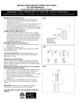
CONNECTING THE WIRES (Fig. 3)
7 Connect the electrical wire as shown in figure 3, making sure
that all wire connectors are secured. If your outlet has a
ground wire (green or bare copper), connect the ground wire
from the hanger ball and mounting plate to it. Otherwise
connect fixture ground wire directly to the crossbar using the
green screw (C) provided. Tuck the wire connections neatly
into the ceiling junction box as you hold the canopy towards
the ceiling.
FINISHING THE INSTALLATION (Fig.1)
8 Align the canopy (G) onto screws (D) and secure with cap nuts
(E).
9 Place glass (S) onto hexagonal stud (R) and secure with
rubber washer (P) and screw (T). Thread rod (N) to joint (M).
10 Align glass (J) to rod (N) and secure with finial (K).
Your installation is now complete. Return power to the junction box
and test the fixture.
CAUTION/ATTENTION: When handling the fixture, do not apply
pressure to the LEDs. Hold the fixture by the frame only.
Fig.1
Fig.3

INSTALLATION INSTRUCTIONS FOR P1072-L
For LED Pendant OR Semi-flush mount
READ AND SAVE THESE INSTRUCTIONS
W A R N I N G ! S H U T P O W E R O F F AT F U S E O R C I R C U I T B R E A K E R
A V E R T I S S E M E N T ! C O U P E R L E C O U R A N T A U N I V E A U D E S F U S I B L E S O U D O D I S J O N C T E U
ASSEMBLING THE FIXTURE (Fig.2)
1 Shut off power at the fuse box or circuit breaker. If necessary,
remove the old fixture including the mounting hardware.
2 Carefully remove the fixture from the carton and check that all
parts are included as show in Figure 1.
3 Thread the two screws (D) into the pre-drilled holes on the
crossbar (A) (Part#A-010) spaced the same distance apart as
the holes in canopy (G). Secure mounting strap (A) to the
junction box using mounting screws (B) (Size: 8*32*1/2"L). The
side of the mounting back plate marked “GND” must face out.
4 Thread rod F3 (Part#W30-3-613) to nipple (I). Pass the wires
carefully through rod during assembly. Next place canopy (G)
over rod (F3) and secure steel washer (Y4), key washer (Y1),
support cable (Y2) with hex nut (Y3).
5 The support cable is provided to support the weight of the
fixture while wiring. Align the fixture to crossbar (A) and attach
hook (Y2-1) on the end of support cable (Y2) into the center
pre-drilled hole on crossbar (A). Carefully allow the support
cable to support the weight of the fixture while wiring.
CONNECTING THE WIRES (Fig. 3)
6 Connect the electrical wire as shown in figure 3, making sure
that all wire connectors are secured. If your outlet has a
ground wire (green or bare copper), connect the ground wire
from the hanger ball and mounting plate to it. Otherwise
connect fixture ground wire directly to the crossbar using the
green screw (C) provided. Tuck the wire connections neatly
into the ceiling junction box as you hold the canopy towards
the ceiling.
FINISHING THE INSTALLATION (Fig.2)
7 Align the canopy (G) onto screws (D) and secure with cap nuts
(E).
8 Place glass (S) onto hexagonal stud (R) and secure with rubber
washer (P) and screw (T). Thread rod (N) to joint (M).
9 Align glass (J) to rod (N) and secure with finial (K).
Your installation is now complete. Return power to the junction box
and test the fixture.
CAUTION/ATTENTION: When handling the fixture, do not apply
pressure to the LEDs. Hold the fixture by the frame only.
Replacing LED module (Fig. 4)
The LED module can be replaced by a qualified electrician without
cutting of wire and without damage to any decorative element to
which the fixture is attached.
Warning: Turn off power at the circuit breaker before replacing
LED module.
a. Loosen finial (K) and remove glass (J).
b. Loosen rod (N), screws (T), rubber washer (P) and remove
glass (S).
c. Loosen hexagonal stud (R), screw (Q), rubber washer (U).
Carefully remove LED module (P) from pan and disconnect the
wire using screwdriver from wire connector (V).
d. Reverse steps a-c for installing the new LED module.
Note: The LED module should be provided by a specified supplier.
IMPORTANT: Fixture should be installed by a qualified electrician to
ensure proper wiring and installation.
Dimmable with ELV and/or LED compatible wall dimmer
switches.
Page 2/2
Fig.2
Fig.3
Fig.4
/