Product Specication
MXG series – Innovative functionality / exible installation
▪ Flexible assembly
▪ Small space is required
▪ RGB and YUV interpolation algorithms on board
▪ Bandwidth up to 1000 Mbit/sec for fast multi-camera operation
▪ Flexible system architecture due to cable length up to 100 m
▪ Baumer driver for reliable image transfer
▪ PoE (Power over Ethernet)
Camera Type
Sensor
Size
Resolution
Full Frames
[max. fps]
CCD Sensor (monochrome / color)
MXG02 / MXG02c
1/4" 656 x 490 160
MXG12 / MXG12c
1/3" 1288 x 960 42
MXG20 / MXG20c
1/1.8" 1624 x 1228 27
CMOS Sensor (monochrome / color)
MXGC20 / MXGC20c
2/3" 2044 x 1084 55
MXGC40 / MXGC40c
1" 2044 x 2044 29
System Requirements
Single-camera system Multi-camera system
Minimum Recommended Minimum Recommended
CPU
Intel
®
Pentium
®
4
or comparable
processor
Intel
®
Core™ Duo comparable processor
Clock
2.5 GHz > 2.5 GHz 2.5 GHz 3 GHz
RAM
1024 MB 2048 MB 2048 MB > 2048 MB
Operating
system
(OS)
Microsoft
®
Windows
®
XP incl. Service Pack 2 or higher
Microsoft
®
Windows
®
XP x64 incl. Service Pack 2 or higher
Microsoft
®
Windows Vista™ 32 / 64 bit systems
Microsoft
®
Windows 7 32 / 64 bit systems
Linux
®
32 / 64 bit systems from Kernel 2.6.xx
Graphic
recommended resolution 1280 x 1024, color depth at least 16 bit
Ethernet
Gigabit Ethernet compliant NIC (recommended Intel
®
chipset)
Framework
(optional)
Windows
®
OS: .NET™ Framework 2.0 or higher
Linux
®
OS: Mono 1.2.4 or higher
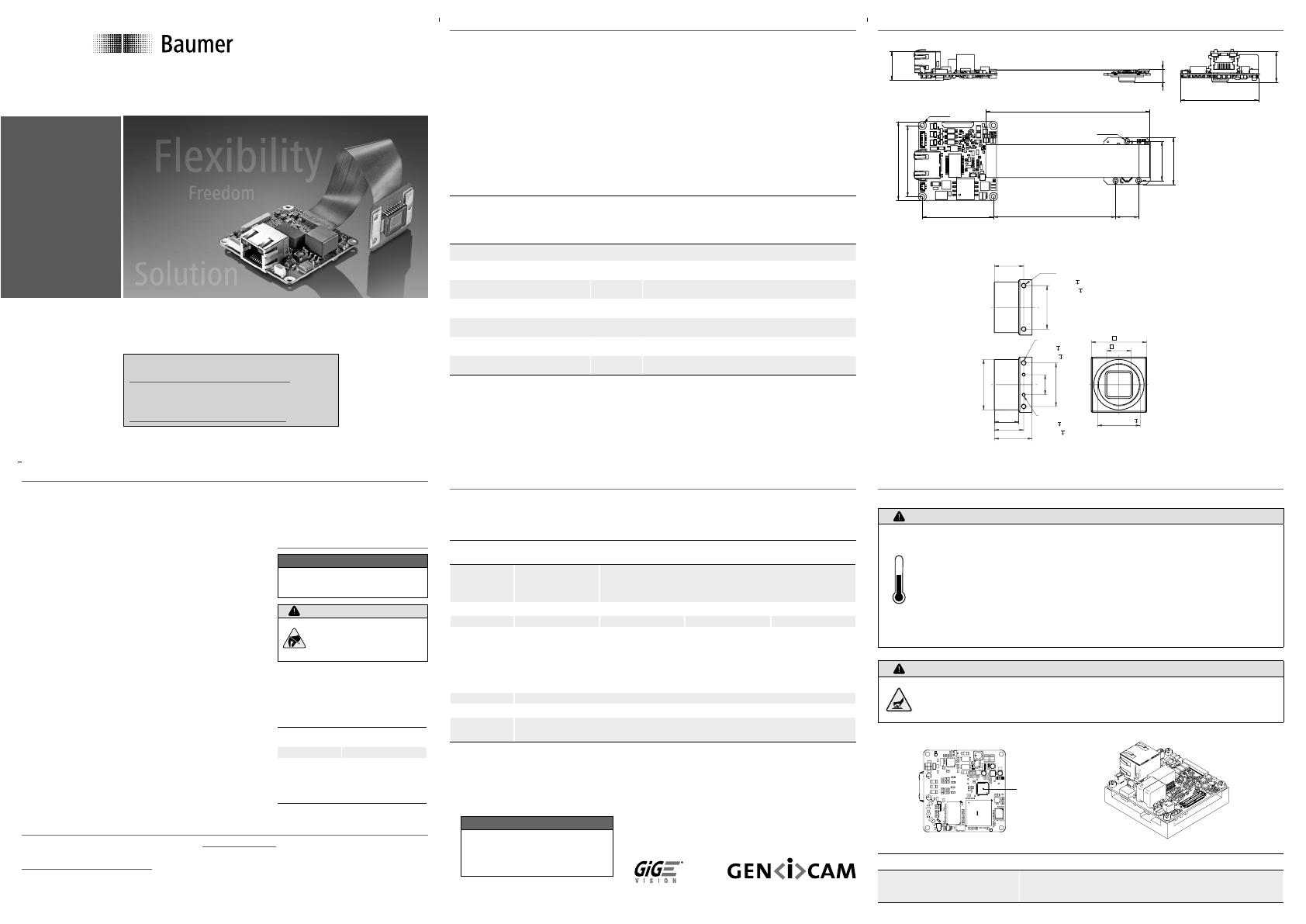
Dimensions
48
43,4
14
24
28,5
43,4
100
74,45
17,6
8
48
18,8
2x
M3/ 3
2,46/ 6
17,5
26
26
12
2x
M3/ 3
2,46/ 6
2x
M2/ 3
1,57/ 6
22,5
17,5
14,5
Ø 30
33
14,5
UN 1"-32 12
C-Mount adapter (optional)
2,7ø
4x
1,8ø
3x
Safety
Further Information
For further information on our products visit www.baumer.com
For technical issues, please contact our technical support:
support.cameras@baumer.com · Phone +49 (0)3528 4386-0 · Fax +49 (0)3528 4386-86
© Baumer Optronic GmbH · Badstrasse 30 · DE-01454 Radeberg, Germany
Technical data has been fully checked, but accuracy of printed matter not guaranteed.
Subject to change without notice. Printed in Germany 11/20. v24 11094214
CE
The Baumer MXG Board level cameras are delivered
without housing. The housing design is critical to the elec-
tromagnetic interference characteristics of a camera.
Therefore no CE certication tests regarding electroma-
gnetic interference have been performed for MXG board
level cameras.
Users who design MXG board level cameras into their
systems should perform appropriate testing regarding
electromagnetic interference.
Safety Precautions
Notice
See User´s Guide for the com-
plete safety instructions!
Caution
Observe precautions for
handling electrostatic
sensitive devices!
▪ Protect the sensor from dirt and
moisture.
▪ Avoid camera contamination by
foreign objects.
Environmental Requirements
Storage temp. -10°C ... +70°C
Operating temp. see Heat Trans-
mission
Humidity 10 % ... 90 %
Non-condensing
Quick Start Guide
MXG Gigabit Ethernet cameras
Notice
Further technical details (e.g.
power supply) available in
the respective data sheets.
Heat Transmission
Caution
Heat can damage the camera. Provide adequate dissipation of heat,
to ensure that the temperatures does not exceed the value in the table
below.
As there numerous possibilities for installation, Baumer do not speciy a
specic method for proper heat dissipation.
For applications with a corresponding free space, the use of the Baumer
heat sink (No. 11098288) is recommended.
Caution
Device heats up during operation.
Irritation of skin possible.
Don’t touch camera and/or heat sink during operation.
Measure Point Maximal Temperature
T 70°C (158°F)
T
Download latest camera software:
www.baumer.com/vision/software
Download latest technical documentation:
www.baumer.com/cameras/docs

