System Requirements
Single-camera system Multi-camera system
Minimum Recommended Minimum Recommended
CPU
Intel
®
Pentium
®
4
or comparable
processor
Intel
®
Core™ Duo comparable processor
Clock
2.5 GHz > 2.5 GHz 2.5 GHz 3 GHz
RAM
1024 MB 2048 MB 2048 MB > 2048 MB
Operating
system
(OS)
Microsoft
®
Windows
®
XP incl. Service Pack 2 or higher
Microsoft
®
Windows
®
XP x64 incl. Service Pack 2 or higher
Microsoft
®
Windows Vista™ 32 / 64 bit systems
Microsoft
®
Windows 7 32 / 64 bit systems
Linux
®
32 / 64 bit systems from Kernel 2.6.xx
Graphic
recommended resolution 1280 x 1024, color depth at least 16 bit
Ethernet
Gigabit Ethernet compliant NIC (recommended Intel
®
chipset)
Framework
(optional)
Windows
®
OS: .NET™ Framework 2.0 or higher
Linux
®
OS: Mono 1.2.4 or higher
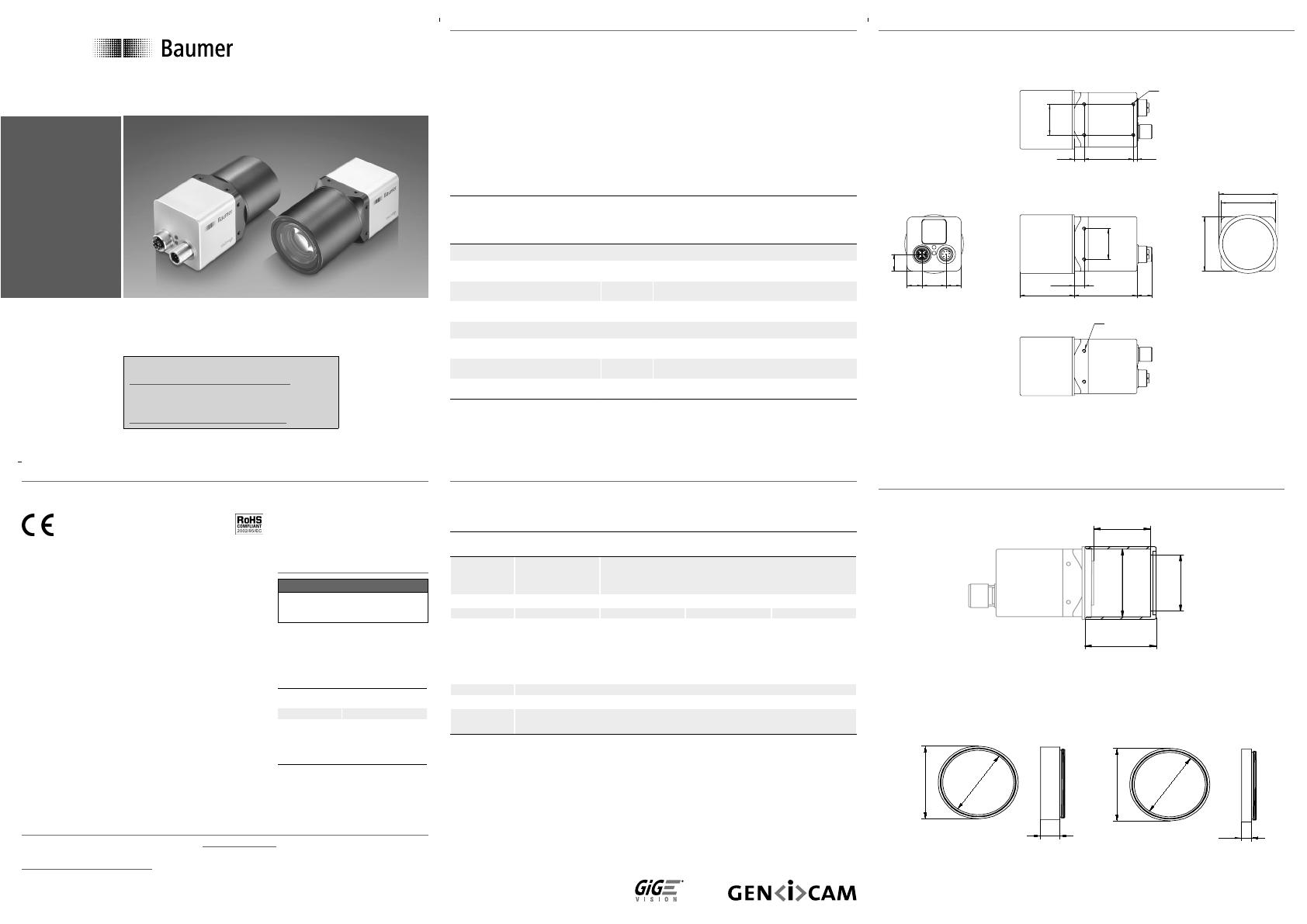
Dimensions
4 - M3 depth 5
8 - M3 depth 5
12,9 12,920,2
26
45,8 52,9 12,9
46
46
14,3
49,5ø
8,3*
41,5 3,1
26
8,3
*7,3 (VLG-23 only)
Dimensions
49,5ø
44
ø
12
Art. No.: 11089149
Art. No.: 11115649
optional
Art. No.: 11088325
46ø
44
38,2ø
35
side view
front view
49,5ø
44
ø
6
side view
front view
36 (VLG-23 only)
Safety
Conformity:
CE, RoHS
Safety Precautions
Notice
See User´s Guide for the com-
plete safety instructions!
▪ Protect the sensor from dirt and
moisture.
▪ Avoid camera contamination by
foreign objects.
Environmental Requirements
Storage temp. -25°C ... +70°C
Operating temp. see Heat Trans-
mission
Humidity 10 % ... 95 %
Non-condensing
Further Information
For further information on our products visit www.baumer.com
For technical issues, please contact our technical support:
support.cameras@baumer.com · Phone +49 (0)3528 4386-0 · Fax +49 (0)3528 4386-86
© Baumer Optronic GmbH · Badstrasse 30 · DE-01454 Radeberg, Germany
Technical data has been fully checked, but accuracy of printed matter not guaranteed.
Subject to change without notice. Printed in Germany 11/20. v16 11110650
Quick Start Guide
VisiLine IP Cameras (Gigabit Ethernet)
Product Specication
VisiLine IP – Innovative functionality / exible installation
▪ Protection class: IP65/67
▪ Flexible assembly
▪ RGB and YUV interpolation algorithms on board
▪ Bandwidth up to 1000 Mbit/sec for fast multi-camera operation
▪ Flexible system architecture due to cable length up to 100 m
▪ Baumer driver for reliable image transfer
▪ PoE (Power over Ethernet)
Camera Type
Sensor
Size
Resolution
Full Frames
[max. fps]
CCD Sensor (monochrome / color)
VLG-02M.I / VLG-02C.I 1/4" 656 x 490 160
VLG-12M.I / VLG-12C.I 1/3" 1288 x 960 42
VLG-20M.I / VLG-20C.I 1/1.8" 1624 x 1228 27
CMOS Sensor (monochrome / color)
VLG-22M.I / VLG-22C.I 2/3" 2044 x 1084 55
VLG-23M.I / VLG-23C.I 1/1.2" 1920 x 1200 53
VLG-40M.I / VLG-40C.I 1" 2044 x 2044 29
CE
We declare, under our sole responsibility, that the previ-
ously described Baumer VisiLine IP cameras conform with
the directives of the CE.
RoHS
All VisiLine IP cameras comply with the recommendation
of the European Union concerning RoHS Rules.
Download latest camera software:
www.baumer.com/vision/software
Download latest technical documentation:
www.baumer.com/cameras/docs


