Page is loading ...

INSTRUCTION MANUAL
MODEL:
HP02W004S1
2HP PORTABLE AIR COMPRESSOR
Heavy Duty Wheels for rough terrain on job sites


IMPORTANT INFORMATION
LIMITED TOOL WARRANTY
PROOF OF PURCHASE
Please keep your dated proof of purchase for warranty and servicing purposes.
REPLACEMENT PARTS
Replacement parts for this tool are available at our authorized HULK service centers across USA. For servicing, contact
or return to the retailer where you purchased your product along with your proof of purchase. Please use the 10 digit part numbers
listed in this manual for all part orders where applicable.
2 Year limited warranty on pumps
1 Year limited warranty on parts & labor
HULK
LIMITED WARRANTY
FOR THIS 2HP AIR COMPRESSOR
HULK makes every effort to ensure that this product meets high quality and durability standards. HULK warrants to the original retail
consumer a 2-year limited warranty as of the date the product was purchased at retail and that each product is free from defects in
materials. Warranty does not apply to defects due directly or indirectly to misuse, abuse, negligence or accidents, repairs or
alterations and lack of maintenance. HULK shall not be liable for death, injuries to persons or property or for incidental,
special or consequential damages arising from the use of our products. To take advantage of this warranty, the manufacturer part
must be returned for examination by the retailer. Shipping and handling charges may apply. If a defect is found, HULK will either repair
or replace the product.
2

IMPORTANT SAFETY INSTRUCTIONS
RISK OF EXPLOSION OR FIRE
WHAT CAN HAPPEN
It is normal for electrical contacts within the motor and pressure
switch to spark.
If electrical sparks from the compressor come in contact with
flammable vapors, they may ignite, causing fire or explosion.
Restricting any of the compressor ventilation openings will
cause serious overheating and could cause fire.
Unattended operation of this compressor could result in
personal injury or property damage.
HOW TO PREVENT
Always operate the compressor in a well ventilated area free of
combustible materials, gasoline or solvent vapors. If spraying
flammable materials, locate the compressor at least 20 feet
away from the spray area. An additional length of hose may be
required.
Store flammable materials in a secure location away from the
compressor.
Never place objects against or on top of the compressor.
Operate compressor in an open area at least 12 inches away
from any wall or obstruction that would restrict the flow or fresh
air to the ventilation openings.
Operate compressor in a clean, dry and well ventilated area.
Do not operate compressor indoors in a confined area.
Always remain in attendance with the compressor when it is
operating.
RISK OF BURSTING
WHAT CAN HAPPEN
1. Failure to properly drain condensed water from the tank,
causing rust and thinning of the steel tank.
2. Modifications or attempted repairs to the tank.
3. Unauthorized modifications to the unloader valve, safety
valve or any other components which control tank pressure.
4. Excessive vibration can weaken the air tank and cause
rupture or explosion.
5. Attachments & Accessories; Exceeding the operating
pressure of air tools can cause them to explode.
HOW TO PREVENT
Drain tank daily or after every use. If the tank develops a leak,
replace tank or get a new air compressor. Never drill into, weld
or make any modifications to the tank or its attachments.
The tank is designed to withstand specific operating pressures.
Never make adjustments or parts substitutions to alter the
factory set operating pressures.
For essential control of air pressure, you must install a
pressure regulator and pressure gauge to the air outlet.
RISK OF BURNS
WHAT CAN HAPPEN
Touching exposed metal such as the compressor head or
outlet tubes, can result in serious burns.
HOW TO PREVENT
Never touch any exposed metal parts on compressor during or
immediately after operation. The compressor will remain hot
several minutes after use.
Do not reach around protective shrouds or attempt
maintenance until the compressor has cooled down
completely.
RISK OF PROPERTY DAMAGE WHEN
TRANSPORTING COMPRESSOR
WHAT CAN HAPPEN
Oil can leak or spill and could result in fire or breathing hazard,
serious injury or death can result. Oil leaks will damage carpet,
paint or other surfaces in vehicles or trailers.
HOW TO PREVENT
Always place compressor on a protective mat when
transporting to protect against damage to vehicle from leaks.
Remove compressor from vehicle immediately apon arrival.
3

SPECIFICATIONS & ELECTRICAL INFORMATION
WARNING
ALL ELECTRICAL INSTALLATIONS MUST BE PERFORMED BY A QUALIFIED ELECTRICIAN. FAILURE TO COMPLY MAY
RESULT IN SERIOUS INJURY! ALL ADJUSTMENTS OR REPAIRS MUST BE PERFORMED WITH THE COMPRESSOR
DISCONNECTED FROM THE POWER SOURCE. FAILURE TO COMPLY MAY RESULT IN SERIOUS INJURY!
POWER SUPPLY
WARNING: YOUR COMPRESSOR MUST BE CONNECTED TO A 110V,
WITH A MINIMUM 15-AMP. BRANCH CIRCUIT. FAILURE TO CONNECT
IN THIS WAY CAN RESULT IN INJURY FROM SHOCK OR FIRE.
GROUNDING
Your compressor must be properly grounded. Not all outlets are properly
grounded. If you are not sure if your outlet is properly grounded, have it
checked by a qualified electrician.
WARNING: IF NOT PROPERLY GROUNDED, THIS COMPRESSOR
CAN CAUSE ELECTRICAL SHOCK, PARTICULARLY WHEN USED IN
DAMP LOCATIONS. TO AVOID SHOCK OR FIRE, IF THE POWER CORD
IS WORN OR DAMAGED IN ANY WAY, HAVE IT REPLACED IMMEDI-
ATELY.
If this compressor should malfunction or breakdown, grounding provides a
path of least resistance for electric current, to reduce the risk of electric
shock. This compressor is equipped with a cord having an grounding
conductor and grounding plug. The plug must be plugged into an
appropriate outlet that is properly installed and grounded in accordance
with all local codes and ordinances.
WARNING: TO MAINTAIN PROPER GROUNDING, DO NOT REMOVE OR
ALTER THE GROUNDING PRONG IN ANY MANNER.
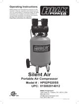
110V OPERATION
As received from the factory, your compressor is ready to run for 110V
operation. This machine is intended for use on a circuit that has an outlet
and a plug which looks like the one illustrated in Fig.1.
WARNING: DO NOT USE A TWO-PRONG ADAPTOR FOR THEY ARE
NOT IN ACCORDANCE WITH LOCAL CODES AND ORDINANCES.
NEVER USE IN USA.
FIGURE 1
LENGTH OF
CONDUCTOR
0-25 FEET
26-50 FEET
51-100 FEET
WIRE SIZES REQUIRED
(AMERICAN WIRE GAUGE)
110V LINES
NO.12
NO.12
NO.10
FIGURE 2
EXTENSION CORDS
The use of any extension cord will cause some loss of power. IT
IS RECOMMENDED TO USE A LONGER AIR HOSE INSTEAD
OF AN EXTENSION CORD. If you do not have a choice, use the
table in Fig.2 to determine the minimum wire size
(A.W.G-American Wire Gauge) extension cord. Use only 3-wire
extension cords which have 3-prong grounding type plugs and
3-hole receptacles which accept the tool’s plug.
For circuits that are further away from the electrical circuit box, the
wire size must be increased proportionately in order to deliver
ample voltage to the compressor motor. Refer to Fig.2 for wire
length and size.
PROPERLY GROUNDED OUTLET
CURRENT CARRYING
PRONGS
GROUNDING
PRONG
SPECIFICATIONS
Model ................................................................................................................................................................................HP02W004S1
Voltage ............................................................................................................................................................................................110V
Horsepower ....................................................................................................................................................................................2HP
Amperage ......................................................................................................................................................................................11.5A
RPM (no load speed)
.....................................................................................................................................................................1720
Phase .
...................................................................................................................................................................................................1
Hertz
..............................................................................................................................................................................................60Hz
Operating pressure
..................................................................................................................................................................125 PSI
Tank size
..............................................................................................................................................................................4 GALLON
4

OPERATION CONTROLS
AIR COMPRESSOR PUMP. To compress air, the piston moves up and down in the cylinder. On the
downstroke, air is drawn in through the intake valves. The exhaust valves remain closed. On the
upstroke of the piston, air is compressed. The intake valves close and compressed air is forced out
through the exhaust valves.
CHECK VALVE (A) FIG.3. When the air compressor is operating, the check valve is “open”,
allowing compressed air to enter the air tank. When the air compressor reaches “Cut-Out” pressure,
the check valve “closes”, allowing air pressure to remain inside the air tank.
ON/AUTO OFF SWITCH (A) FIG.5. Turn this switch ON by lowering lever downwards to provide
power to the automatic pressure switch and lift to turn compressor OFF.
PRESSURE SWITCH (C) FIG.5. The pressure switch automatically starts the motor when the tank
pressure drops below the factory set “Cut-In” pressure. It also stops the motor when the air tank
pressure reaches the factory set “Cut-Out” pressure.
REGULATOR (B) FIG.6. The air pressure coming from the air tank is controlled by the regulator.
Turn the regulator knob clockwise to increase pressure and counterclockwise to decrease pressure.
To avoid minor readjustment after making a change in the pressure setting, always approach the
desired pressure from a lower pressure. When reducing from a higher to a lower setting, first reduce
adjusted while operating the accessory.
OUTLET PRESSURE GAUGE ( C) FIG.6. The outlet pressure gauge indicates the air pressure
available at the outlet side of the regulator. The pressure is controlled by the regulator and is always
less than or equal to the tank pressure.
TANK PRESSURE GAUGE (A) FIG. 6.The tank pressure gauge indicates the reserve air pressure in the
tank.
COOLING SYSTEM. This compressor contains an advanced design cooling system. The cooling
system works when air is being expelled.
DRAIN VALVE (A) FIG. 4. The drain valve is located at the base of the air tank and is used to drain
condensation from the tank to prevent corrosion. Drain tank at the end of each use.
MOTOR THERMAL OVERLOAD PROTECTOR (RESET (B) FIG. 3). The electric motor has an
automatic thermal overload protector. If the motor overheats for any reason, the thermal overload
protector will shut off the motor. The motor must be allowed to cool before restarting. Press the reset
button (B).
PRESSURE RELEASE VALVE. The pressure release valve located on the side of the pressure
switch, is designed to automatically release compressed air from the compressor head and the
outlet tube when the air compressor reaches “Cut-Out” pressure or is shut off. The pressure release
valve allows the motor to restart freely. When the motor stops running, air will be heard escaping
from this valve for a few seconds. No air should be heard leaking when the motor is running, or
continuous leaking after unit reaches “Cut-Out” pressure.
SAFETY VALVE (B) FIG. 5. If the pressure switch does not shut off the air compressor at its
“Cut-Out” pressure setting, the safety valve will protect against high pressure by “popping out” at it’s
factory set pressure (slightly higher than the pressure switch “Cut-Out” setting).
WARNING!: If the safety valve does not work properly, over pressurization may occur, causing air
tank rupture or an explosion. Daily, pull the ring on the safety valve to make sure that the safety
valve operates freely . If the valve is stuck or does not operate smoothly, it must be replaced with the
same type of valve before operating again.
5
FIGURE 3
FIGURE 4
FIGURE 6
FIGURE 5
the pressure less than desired, then bring it up to the desired pressure. Depending on the air
requirements of each particular accessory, the outlet regulated air pressure may have to be

BREAK-IN PROCEDURES & OPERATION
LOCATION OF THE AIR COMPRESSOR
Your compressor comes almost completely assembled, the air filter must be installed. Operate the air compressor in a dry, clean, cool, well
ventilated area. The air compressor pump and case are designed to allow for proper cooling. Clean or blow off dust or dirt that collects on the
air compressor. A clean air compressor runs cooler and provides longer service. The ventilation openings on your air compressor are necessary
to maintain proper operating temperature. Do not place rags or other containers on or near these openings.
ADDITIONAL REGULATORS AND CONTROLS
Since the air tank pressure is usually greater than that which is needed, a regulator is employed to control the air pressure ahead of any
individual driven device. Separate air transformers which combine the function of air regulation, moisture and dirt removal should be used where
applicable.
BREAK-IN PROCEDURES
NOTE: SERIOUS DAMAGE MAY RESULT IF THE FOLLOWING BREAK-IN INSTRUCTIONS ARE NOT CLOSELY FOLLOWED. THIS
PROCEDURE IS REQUIRED BEFORE THE AIR COMPRESSOR CAN BE PUT INTO SERVICE, AFTER REPLACING THE CHECK VALVE,
AND WHEN THE PISTON OR THE CYLINDER SLEEVE IS REPLACED.
OPERATING PROCEDURES
Preparation for use:
1. Before attaching an air hose or accessories, make sure the OFF lever is set to “OFF” and the air regulator is closed. Once this is done,
you can now attach a hose or an accessory.
WARNING: Too much air pressure causes a hazardous risk of bursting. Check the manufacturer's maximum pressure rating for air tools and
accessories. The regulator outlet pressure must never exceed the maximum pressure rating of the tool being used.
3. Turn the “ON/AUTO OFF” lever to “ON/AUTO” and allow tank pressure to build. Motor will stop when tank pressure reaches “Cut-Out”
pressure.
4. Open the regulator by turning it clockwise. Adjust the regulator to the correct pressure setting. The compressor is ready for use.
5. Always operate the air compressor in well ventilated areas; free of gasoline or other solvent vapors. Do not operate the compressor near the
spray area.
After Use:
6. Set the “ON/AUTO OFF” lever to “OFF”.
7. Turn the regulator counterclockwise to set the outlet pressure to zero.
8. Disconnect the air tool or accessory.
9. Pull ring on safety valve (B) Fig. 5, allowing air to bleed from the tank until tank pressure is approximately 20 psi. Release safety valve ring.
10. Drain water from air tank. Turn drain valve (A) Fig. 4, counterclockwise to open.
WARNING!: WATER WILL CONDENSE IN THE AIR TANK. IF NOT DRAINED REGULARLY, WATER WILL CORRODE AND WEAKEN THE
AIR TANK CAUSING A RISK OF AIR TANK RUPTURE.
NOTE: If drain valve is plugged, pull ring on safety valve (B) Fig. 5, and hold until air pressure has been released. The valve can then be removed,
cleaned, and reinstalled.
11. After the water has been completely drained, turn drain valve to close. The air compressor can now be stored.
6
A. Fill crankcase with oil as described in “Changing Oil” in the maintenance section on the following page.
B. Set the pressure switch lever to the “OFF” position.
C. Plug the power cord into the correct 110V branch circuit receptacle.
D. Fully open the drain valve (A) Fig. 4, by turning it counterclockwise, to prevent air pressure build-up in the tank.
E. Move the pressure switch lever to “ON/AUTO”. The compressor will start.
F. Run the compressor for 15 minutes. Make sure the drain valve is open and there is no tank pressure build-up by watching the
tank pressure gauge.
G. After 15 minutes, close the drain valve by turning clockwise. The air receiver will fill to “Cut-Out” pressure and the motor
will stop. The compressor is now ready for use.

MAINTENANCE & STORAGE
TROUBLE
No start condition
Low pressure
Safety valve releasing
Oil discharge in air
POSSIBLE CAUSE
Fuse blown or circuit breaker tripped
Loose electrical connections
Overheated motor
Air leak in safety valve
Restricted air filter
Defective check valve
Defective pressure switch or improper
adjustment
Improper oil viscosity
Too much oil in crankcase
Compressor overheated
Restricted air filter
CORRECTIVE ACTION
Check voltage or eliminate extension cord or reset
Check wiring connections
Press the reset button or wait for automatic reset
Check valve manually by pulling upwards on ring. If condition
persists replace valve
Clean or replace as necessary
Replace check valve
Check for proper adjustment and if problem persists, replace
pressure switch
TROUBLE SHOOTING
MAINTENANCE
Before doing any maintenance or adjustments to your air compressor,
the following safety precautions should be taken:
- Disconnect electrical power.
- Drain air tank of pressure.
Daily or before each use
1. Check oil level. The oil level should be centered with the red dot
which appears in the oil sight glass (C) Fig.7.
2. Drain condensation from tank.
3. Check for any unusual noise or vibration.
4. Be sure all nuts and bolts are tight.
Monthly
1. Inspect air system for leaks by applying soapy water to all joints.
Tighten those joints if leakage is observed.
250 hours or six months (whichever comes first)
1. Change compressor oil. See following instructions.
2. Replace oil more often if compressor is used near paint spraying
operations or in dusty environments.
CHANGING OIL
To change oil, oil must be drained from the crank case by unscrewing
and removing oil sight glass (C) Fig.7. Drain oil and replace oil sight
glass. To fill the crank case with oil, first unscrew and remove oil
breather cap (A), pour air compressor oil (SAE 30 or SAE 20 weight
non-detergent compressor oil) into crank case oil opening (B) until the
oil level reaches the red dot at the center mark of the oilsight glass. Secure
oil breather cap (A).
KEEP TOOL CLEAN
Periodically blow out all air passages with dry compressed air. Clean all
plastic parts with a soft damp cloth. NEVER use solvents to clean
plastic parts. They could possibly dissolve or otherwise damage the
material.
CAUTION: Wear safety glasses while using compressed air.
FAILURE TO START
Should your compressor fail to start, check to make sure the prongs on
the cord plug are making good contact in the outlet. Also, check for
blown fuses or open circuit breakers in the line.
STORAGE
1. Set the “ON/AUTO-OFF” lever to “OFF”.
2. Turn the regulator counterclockwise to set the outlet pressure to
zero.
3. Remove the air tool or accessory .
4. Pull ring on safety valve (B) Fig. 5, allowing air to bleed from the tank,
until tank pressure is approximately 20psi. Release safety valve ring.
5. Drain water from air tank. Turn drain valve (A) Fig. 4, counterclock-
wise, to open.
NOTE: If drain valve is plugged, pull ring on safety valve (B) Fig. 5, and
hold until air pressure has been released. The valve can then be
removed, cleaned, and reinstalled.
6. After the water has been completely drained, turn drain valve to
close. The air compressor can now be stored.
7. Protect the electrical cord and air hose from damage by winding
them loosely around the power cord holder posts on the right side.
8. Store the air compressor in a clean and dry location.
FIGURE 7
7
Replace oil with SAE 10W30 or SAE 10W20
non-detergent compressor oil. Drain crankcase and fill to
proper level Air pressure regulated too high
Replace filter

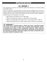
PARTS DIAGRAM MODEL:
HP02W004S1
8

PARTS LIST MODEL: HP02W004S1
9
No. Part Number Description Qty
1
Head Bolts
4
2
Lock washer
4
3
Cylinder head
1
4
Exhaust elbow
1
5
Gasket
1
6
Complete plate & valves
1
7
Gasket
1
8
Cylinder
1
9
Piston
1
10
Piston ring set (3)
1
11
Snap ring
2
12
Connecting rod
1
13
Piston pin
1
14
Gasket
1
15
Eye Bolts
2
16
Lock washer
2
17
Crank shaft
1
18
Crank Shaft Bolt
1
19
Gasket
1
20
Front housing cover
1
21
hex. bolt
1
22
O-ring
1
23
Oil sight glass
1
24
hex. bolt
4
25
Breather
1
26
Motor housing
1
27
Oil seal
1
28
Ball Bearing
1
29
Armature
1
30
Ball Bearing
1
31
Motor Winding
1
32
Thrust Washer
1
33
Back cover
1
34
Lock washer
4
35
Hex. bolt
4
36a
Centrifugal starting switch
1
36b
Hex. bolt
1
36c
Starter point
1
37a
Pan head screw
2
37b
Lock washer
1
38
Running capacitor
1
39
Starting capacitor
1
40a
Hex. Nut
1
40b
Lock Washer
1
No. Part Number Description Qty
42
Fan
1
43
O-ring
1
44
Plastic cover
1
45
hex. bolt
4
46
Pressure switch
1
49
Power cord
1
50
Strain relief
2
51
Safety valve
1
53
Connector pipe
1
54
Double connector pipe
1
55
Flexible line
1
56a
Check valve
1
56b
Elbow
1
57
Connector elbow pipe
1
58
Complete unloading pipe
1
60
Pressure Regulator
1
61
Quick connect coupler(female)
2
62
Pressure gauge
2
63
Exhaust pipe
1
64
Flare
2
65a
Tank
1
65b
Handle
1
66
Drain valve
1
67a
Cap screw
2
67b
Lock washer
2
67c
Hex. Nut
2
68
Lock knob
2
69
Rubber foot
2
70
Washer
2
71
Tapping screw
2
72
8" Pneumatic tire
2
73
Nylon hex. nut
2
74
Motor Bracket
1
75
Rubber washer
1
76
hex. bolt
4
77
Panel
4
78
Lock washer
1
79
Pan head screw
8
80
Pan head screw
4
81
Washer
16
82
Hex. Nut
8
83
Air Filter
1
84
Thermal Overload
1
HB30106070
LW30502060
CH00106003
EE40101010
GA40501060
PV40206000
GA40502060
CY00603007
PI00747001
PR40302000
SR30503120
CR00802001
PP40901002
GA40503020
EB30108040
LW30502080
CS00902001
CB30108011
GA40402000
HC00502001
HB30306001
OR30603000
OG30601000
HB30306021
BR30602001
MH00202000
OS30602001
BB30701003
AR10603010
BB30701001
MW10603011
TW30505000
BC00403005
LW30505051
HB30205192
CS44402020
HB30505051
SP30315001
HS30108040
LW30502080
RC40801010
SC40802010
HN30501051
LW30502051
FA40707000
OR30504140
PC50102000
HB30305012
PS50202001
PC50602000
SR30210010
SV50402050
CP50703102
CP50702104
FL51301000
CV50405103
EL40106010
CP50703101
UP50703102
PR50401016-02
QC50503000
PG50301003
EP50803041
FL30408001
TA20305000
HA20201009
DV40602000
CS30106041
LW30406011
HN30804000
LK30503120
RF51001001
WA30501064
TS30325011
PT51003086
HN30410011
MB20201011
RW30501051
HB30405001
PA20201012
LW30501051
HS30315011
HS30306031
WA30501051
HN30502051
AF50901140
TO41001040

/