Page is loading ...

88053200 03/2014
20 Gallon Air Compressor
Model: 53200
*Actual product may vary slightly

2
CALIFORNIA PROPOSITION 65
WARNING: You can create dust when you cut, sand, drill or grind materials such
as wood, paint, metal, concrete, cement, or other masonry. This dust often
contains chemicals known to cause cancer, birth defects, or other reproductive
harm. Wear protective gear.
WARNING: This product or its power cord may contain chemicals, including
lead, known to the State of California to cause cancer and birth defects or other
reproductive harm. Wash hands after handling.
Important!
When using equipment, a few safety precautions must be observed to avoid injuries
and damage. Please read the complete operating manual with due care. Keep this
manual in a safe place, so that the information is available at all times. If you give the
equipment to any other person, give them these operating instructions as well. We
accept no liability for damage or accidents which arise due to non-observance of these
instructions and the safety information herein.
Important Operating Instructions
SPECIFICATIONS
Running horsepower:
CFM @ 40 PSI:
CFM @ 90 PSI:
Voltage:
Motor:
Tank:
Oil Lubrication
2 HP
6 CFM
5 CFM
Single Phase; 120V
3200 RPM
20 gallons
Any failures made in following the safety regulations and instructions may result
in an electric shock, fire, and/or serious injury.

3
• Keep work area clean. Messy areas and cluttered workbenches invite personal injury
and/or property damage.
• Keep children and visitors away. All children should be kept away from the work area.
DO NOT let children handle the compressor or extension cord. Maintain a safe distance
for any person near the work area.
• Operating any tools or equipment under the influence of drugs, alcohol, or medication
can cause personal injury to yourself and others.
• Wear proper apparel. Remove your jewelry before using air compressor. Do not wear
loose clothing, necklaces, rings, bracelets, or other jewelry, which may get caught in
moving parts. Nonskid footwear and electrically non-conductive gloves are highly
suggested while working. Wear protective hair covering to contain long hair.
• Protect your eyes. The operation of any air compressor can result in foreign objects
being thrown into the eyes, which can result in severe eye damage. Always wear eye
protection that meets ANSI Z28.1 specifications during air compressor operation.
Eyeglasses are not always safety glasses.
• Be responsible for your hearing. Wear hearing protection during extended periods of
operation.
• Use the right tool. Use tools properly and for their intended use. Do not force a small
tool to do the job of a heavy-duty tool. Using the right tool to do the right job will make
doing the job safer.
• Check damaged parts before use of any air tools or attachments. A guard or other part
that is damaged should be carefully checked to ensure that it will operate properly and
perform its intended function. Check for misalignment or binding of moving parts,
breakage of parts, mounting, or any other conditions that may affect tool operation. A
guard or other part that is damaged should be properly replaced. See replacement parts
list for additional details.
• Avoid unintentional starting. Be sure that your air compressor is in the OFF position
before plugging it into a power cord or electrical receptacle.
• Store all maintenance tools away from the immediate area before turning ON your air
compressor.
Important Operating Instructions
GENERAL SAFETY INSTRUCTIONS

4
• Do not overreach. Proper footing and balance is a must at all times while using tools.
Unstable support may lead to personal injury. Do not stand on the tool. Serious injury
could result if the tool tips over or you accidentally contact the tool.
• Never leave the air compressor running unattended. Always turn the power to the OFF
position and do not leave the air compressor until it comes to a complete stop.
• When using air accessories, consult the owner’s manual provided by the manufacturer.
The use of improper accessories may cause risk of injury to yourself and others.
• Always make sure the tool is in the OFF position and unplugged from the electrical
receptacle when making adjustments, changing parts, or performing any maintenance.
• Secure work. When possible, the use of clamps or a holding device is much safer than
holding the work piece with your hands.
• Keep protective guards in place and in proper working condition.
• Maintain tools and equipment with care. they will function better and more safely when
kept clean and in good working condition. Keeping the air compressor clean, dry, and free
of grime will add to its life and performance.
• Childproof the workshop. The use of master switches and padlocks is highly
recommended. Remove starter keys where applicable.
Drain liquid from air tank daily
• Use the drain valve located on the bottom of the lower air tank to drain. Failure to
properly drain liquid from the tank will cause rust from moisture buildup, which weakens
the tank and could lead to a violent tank explosion. Periodically inspect the tanks for
unsafe conditions such as corrosion, cracked welds, and leaks.
• Release air slowly when draining moisture or depressurizing the air compressor. Fast
moving air will stir up dust, dirt, and debris, and may be harmful.
Risk of fire or explosion
• Avoid dangerous environments. Do not spray combustible/flammable liquid in a confined
area. Spray area must be well ventilated. Do not smoke while spraying or spray where
spark or flame is present. Arcing parts - keep compressor at least 20 ft. away from
spraying area and all explosive vapors. Do not use compressor near gasoline or other
flammable materials.
Important Operating Instructions
GENERAL SAFETY INSTRUCTIONS

5
• Operate the air compressor in a well-ventilated area. Do not direct paint or other spray
material towards the compressor. Read and follow all safety instructions for the material
you are spraying.
Risk of injury
• Do not direct air stream at body. Use eye protection. Compressor starts automatically.
Do not touch moving parts. Keep guards in place. Compressor does not supply
breathable air.
Risk of bursting
• Do not adjust regulator to result in output pressure greater than marked maximum
pressure of attachment. If a regulator has not been installed, use only attachment rated at
200 PSI or higher. Do not weld on or repair tank - A DAMAGED TANK MUST BE
REPLACED IMMEDIATELY. Do not operate without proper safety valve in place.
• Never attempt to repair or make modifications to the tank or its attachments. Welding,
drilling, or any other modifications may weaken the tank, which may result in damage
from rupture or explosion. Never remove or attempt to adjust the pressure switch, safety
valve, or other components that control tank pressure. Never substitute parts or attempt
to alter the factory set operating pressures.
Risk of burns
• Touching exposed metal such as the compressor head or exhaust tube can result in
serious burns. Keep hands and fingers away from exposed metal parts on air compressor
during or immediately after operation. Air compressors generate significant heat during normal
operation and will remain hot for some time after use. Do not reach around protective shrouds or
attempt any maintenance until compressor has been allowed to cool.
Risk of flying objects
• Do not direct compressed air stream at people or pets. The powerful compressed air stream can
damage exposed skin and easily propel loose dirt and other small objects at high-speed, resulting
in serious injury. Always wear eye protection that meets ANSI Z28.1 specifications. Use only
OSHA approved air blowguns. Never leave a pressurized air compressor unattended. Shut OFF
air compressor and relieve pressure before performing maintenance or repairs. Do not move the
air compressor while the air tank is pressurized. Never attempt to move the air compressor by
pulling on the air hose.
Important Operating Instructions
GENERAL SAFETY INSTRUCTIONS

6
Risk of falling
• Portable air compressors can fall from a table, workbench, or roof causing damage to the
compressor and could result in serious injury or death to the operator. Always operate air
compressor in a stable and secure position to prevent accidental movement of the unit. Never
operate air compressor on a roof or other elevated position. Use additional air hose to reach high
locations.
Air tools and accessories
• Do not exceed the pressure rating of any air tool, spray gun, air accessories, or inflatables.
Excess pressure can cause them to explode, resulting in serious injury. Follow the manufacturer’s
recommended pressure settings for all air tools and air accessories.
Important Operating Instructions
GENERAL SAFETY INSTRUCTIONS
INSTALLATION & LOCATION
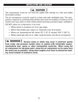
Caution: In order to avoid damaging the air compressor, do not allow the unit to be tilted from the
normal position when operating.
The compressor must be run with the rubber feet resting on a flat and stable horizontal surface.
The air compressor must be used in a clean and well-ventilated area.The compressor requires an
unobstructed airflow and must be located a minimum of 20 inches from any walls or other
obstructions that may prevent proper ventilation.
Caution: DO NOT place air compressor in an area:
• Where there is evidence of oil or gas leaks.
• Where flammable gas vapors or materials may be present
• Where temperatures fall below 32°F or exceed 104°F.
• Where extremely dirty air or water could be drawn into the air compressor.
WARNING: Serious injury or death may occur if electrical sparks from motor and pressure
switch come in contact with flammable vapors, combustible dust, gases, or other
combustible materials. When using the air compressor for spraying paint, place the air
compressor as far away from the work as possible, using extra lengths of air hose to
extend the working reach instead of extension cords.

7
This product should be grounded. In the event of an
electrical short circuit, grounding reduces the risk of electric
shock by providing an escape wire for the electric current.
This product is equipped with a cord having a grounding
wire with an appropriate grounding plug. The plug must be
plugged into an outlet that is properly installed and
grounded in accordance with all local codes and
ordinances.
DANGER: Improper installation of the grounding plug can
result in a risk of electric shock. If repair or replacement of
the cord is necessary, do not connect the grounding wire to
either flat blade terminal. The wire with GREEN insulation
with or without yellow stripes is the grounding wire.
This product is for use on a nominal 120-volt circuit and has
a three-prong grounding plug that looks like the plug
illustrated in Figure 1. A temporary adapter similar to the
adapter illustrated in Figure 1-B may be used to connect
this plug to a 2-pole receptacle as shown in figure 1-B when
a properly grounded outlet is not available. The temporary
adapter shall be used only until a properly grounded outlet
(Figure 1-A) is installed by a qualified electrician. Tab for
grounding screw, lug, or similar part extending from the
adapter must be connected to a permanent ground such as
a properly grounded outlet box cover. Whenever the
adapter is used, it must be held in place by a metal screw.
The use of a GFCI outlet is strongly recommended. The
third prong is to be used to ground the tool and provide
protection against electrical shock. Never remove the third
prong.
Check with a qualified electrician or serviceman if the
grounding instructions are not completely understood, or if
in doubt as to whether the product is properly grounded. Do
not modify the plug provided. If it will not fit the outlet, have
the proper outlet installed by a qualified electrician.
Important Operating Instructions
GROUNDING INSTRUCTIONS

8
CAUTION: The use of an extension cord with this product is not recommended as this
can result in the loss of power to your air compressor which can prevent the motor from
starting or running properly. This can also cause your fuse to blow or circuit breaker to
trip. Running your air compressor on an undersized extension cord will cause permanent
damage to internal switches and overheating of the electric motor. Use an additional
length of air hose rather than an extension cord.
If you must use an extension cord, it should be plugged into a GFCI found in circuit boxes
or protected receptacles. Use only UL listed 3-wire extension cords that have a 3-blade
grounding plug and a 3-slot receptacle that will accept the plug on the product. Make sure
your extension cord is in good condition. When using an extension cord, be sure to use
one heavy enough to carry the current your product will draw. Refer to the guide for
minimum gauge required for extension cords.
Important Operating Instructions
EXTENSION CORDS
Use only extension cords that are intended for outdoor use. These cords are identified by
a marking “ACCEPTIBLE FOR OUTDOOR APPLIANCES, STORE INDOORS WHEN
NOT IN USE.” Examine extension cord before use. DO NOT USE DAMAGED
EXTENSION CORDS. Do not pull on cord to disconnect from receptacle; always
disconnect by pulling on plug. Keep cord away from heat and sharp edges. Always shut
OFF the air compressor AUTO/ON pressure switch before unplugging the compressor.
Always disconnect the extension cord from the receptacle before disconnecting the
product from the extension cord.
WARNING: Avoid electrical shock hazard. Never use this compressor with a
damaged or frayed electrical cord or extension cord. Inspect all electrical cords
regularly. Never use in or near water or in any environment where electric shock is
possible. To reduce the risk of electrocution, keep all connections dry and off the
ground. Do not touch the plug with wet hands.

9
Important Operating Instructions

10
8. SAFETY RELIEF VALVE (I): This compressor is equipped with a safety relief valve
that is designed to prevent system failures by relieving pressure from the system when
the air pressure reaches a predetermined level. The safety relief valve is preset by the
manufacturer. DO NOT attempt to modify or remove the safety relief valve.
9. AIR COUPLER: The air coupler is preinstalled into standard 1/4” NPT (F) threads in
the pressure manifold. Use PTFE thread-sealing tape on the threads to make sure you
have an airtight connection when replacing quick connect couplers.
Important Operating Instructions
10. MOTOR THERMAL OVERLOAD PROTECTOR (J):
The electric motor has an automatic thermal overload
protector. If the motor overheats for any reason, the
thermal overload protector will shut off the motor. The
motor must be allowed to cool before restarting. Press
the reset button (J) after 15 minutes.
5. PRESSURE REGULATOR (E&F): The regulator allows you to select the amount of air
pressure that is output through the air hose into tools and accessories. Turn the pressure
regulator knob clockwise to increase discharge pressure, and counter clockwise to
decrease discharge pressure. Please refer to the air delivery requirements of your tool for
the proper pressure settings.
NOTICE: Be careful not to over tighten pressure regulator knob when it “bottoms out” as
this may damage pressure regulator.
6. OUTLET PRESSURE GAUGE (G): The
outlet pressure gauge provides a reading of
the air pressure at the outlet side of the
regulator. This pressure is controlled by the
pressure regulator and is always less than or
equal to the air tank pressure.
7. AIR TANK PRESSURE GAUGE (H): The
tank pressure gauge provides a reading of the
air pressure inside of the compressor tank.
* actual model may vary slightly

11
Important Operating Instructions
Regulator Assembly
1. Remove the plugs from the plastic bag.
Apply thread sealant tape to the threads.
2. The assembly is designed to be attached
only to the pressure switch outlet. Insert the
pipe nipple and turn the assembly
clockwise. Tighten until snug. The gauge
should be oriented the same as the gauge
already on the pressure switch. Attach the
hose and tire chuck. Check for leaks with
soapy water.
ASSEMBLY

12
Important Operating Instructions
Handle Assembly
1. Remove the handle screw from the base
plate, if preinstalled.
2. Insert the handle into both sides of the
base plate. Squeeze handle to fit into the
special openings in the plate.
3. Place a short piece of wood against the
end of the handle and tap with a mallet or
hammer until the hole in the handle lines
up with the holes in the base plate.
4. Insert and tighten the handle screw into the hole in the base plate through the handle.
Ensure the screw goes all the way through the handle.
Wheel Assembly
1. Insert the shoulder bolt through the wheel hub
with the bolt head on the opposite side of the
protruding section.
2. For the 8” diameter wheels, insert the shoulder
bolt into the lowest hole of the tank axle iron and
secure tightly with a locknut.
3. For the 10” diameter wheels, insert the shoulder bolt into the upper hole in the tank axle
iron and tightly secure with the locknut.
4. Repeat step 3 or 4 on the opposite side.
Note: When the unit is assembled, the tank should slope slightly towards the drain valve to
allow the tank to drain properly.
Breather Installation
Remove the cap from the oil fill opening.
Install the breather.

13
Important Operating Instructions
Oil Addition
The oil capacity of this unit is approximately 8.5 ounces. Synthetic oil is recommended.
Use 10W-30 100% non-detergent synthetic oil for best results. Single viscosity, ISO100
(SAE30) non-detergent compressor oil can also be used.
CAUTION: Do not use petroleum based automotive oil with this unit. It will cause carbon
deposits which will require the unit to be serviced more frequently and reduce the life of the
unit.
Note: This compressor must be filled with oil before startup.
CAUTION: Do not attach air tools to the compressor until startup is completed and the unit
checks OK.
OPERATION
1. Check for proper oil level.
2. Turn the regulator knob clockwise to open
air flow.
3. Turn the pressure switch lever or knob to
the OFF position and plug in the power cord.
4. Turn the pressure switch lever or knob to
AUTO and run the unit for 30 minutes to
break in the pump parts.
5. Turn the regulator knob fully counterclockwise. The unit will build to maximum preset
pressure and automatically shut off.
6. Turn the regulator knob clockwise to cause air to bleed off. The unit will restart at preset
pressure.
7. Turn the pressure switch lever or knob to OFF and unplug the power cord. Slowly turn
the regulator knob clockwise so that all the air pressure can be released.
8. Attach an air hose (not included) and then add an air chuck or other tool (not included)
to the open end of the hose. Use teflon tape to eliminate air leaks when attaching tools or

14
Important Operating Instructions
air hose. Plug in the power cord. Turn the pressure switch lever to the AUTO position.
When the full pressure is reached, turn the regulator knob clockwise until desired outlet
pressure is achieved.
9. After use, turn the pressure switch lever or knob to OFF.
10. If the compressor is not used for an extended period of time, bleed the air from the line
and use the drain valve to drain water from the tank.
Note: Electric models are equipped with a pressure switch that automatically turns the
motor OFF when the tank reaches a preset level. After air is used from the tank and it
drops to a preset low level, the pressure switch will automatically turn the motor back on.
MAINTENANCE
WARNING: Disconnect the unit from the power source and release all pressure from the
tank before attempting to perform any maintenance or service to the unit.
Perform the following test to verify the operation of the safety valve weekly and follow the
maintenance schedule.
1. Pull the ring on the safety valve and allow the ring to snap back into its normal position.
This valve automatically releases air if the tank pressure exceeds the preset maximum.
CAUTION: A large amount of fast moving air will be released if the safety valve is pulled
with air pressure in the tank.
WARNING: Do not attempt to tamper with this valve. It should be checked before each
use. If air leaks after the ring has been released or the valve is stuck and cannot be
actuated by the ring, the valve must be replaced. Do not use the unit until the ring has
been replaced.
2. With the motor OFF and unplugged, clean debris from the motor, flywheel, tank, air
lines, and pump cooling fins.
Drive Belt
Belts will stretch with normal use. Properly adjusted, a 5-pound pressure is applied to the
belt between the motor pulley and the pump and it will deflect the belt approximately 1/2-
inch.

15
Important Operating Instructions
STORAGE
1. When not in use, the hose and compressor should be stored in a cool, dry place.
2. Tanks should be drained of moisture and the hose disconnected and hung with open
ends down to allow moisture to drain.
3. Protect the cord from possible damage by winding the cord loosely around the handle of
the unit or coiling the cord up.
Moisture in Compressed Air
Moisture in compressed air will form droplets as it comes from an air compressor pump.
When humidity is high or when the unit is run for an extended period of time, moisture will
collect in the tank. If a sandblaster or paint spray gun is used, water could be mixed in with
the spray material. A filter or air dryer in the air line will help eliminate moisture when
placed as close to the gun as possible.
Maintenance Schedule.
Maintenance will need to be performed more frequently if the compressor is used in high
humidity or dusty situations.
Daily: Check oil level and drain tank.
Weekly: Check air filter and safety valve.
Monthly: Blow dirt from inside motor and check belt tightness.
Every 3 months: Change oil.

16
Important Operating Instructions
TROUBLESHOOTING GUIDE
Replace with new rings. Maintain oil level
and change oil more frequently
Worn piston rings
Large quantity
of oil in the
discharge air
Note: In an oil
lubricated
compressor
there will always
be a small
amount of oil in
the air stream
Clean filter. Check for other restrictions in
the intake system.
Compressor air intake
restricted
Drain down to full levelExcessive oil in compressor
Use Mobil 1* 10W-30 air compressor oilWrong oil viscosity
Remove head and inspect for valve
breakage, misaligned valves, damaged
valve seats, etc. Replace defective parts
and reassemble.
CAUTION: Install a new head gasket each
time the head is removed.
Leaking or damaged valves
Replace any gaskets proven faulty on
inspection
Blown gaskets
Corrective ActionPossible Cause(s)Symptom
Replace valves or install new gasketBroken valve/blown gasket
Install gasket
Insulating gasket between filter
and head is missing
Pump
overheating
causes air filter
to melt
Clean the air filter elementRestricted air intake
Listen for escaping air. Apply soap solution
to all fittings and connections. Bubbles will
appear at points of leakage. Tighten or
replace leaking fittings or connections.
Air leaks
Reduce air demand or use a compressor
with more capacity
Air demand exceeds pump
capacity
Low discharge
pressure

17
Important Operating Instructions
TROUBLESHOOTING GUIDE
Replace the check valve if the unloader
valve bleeds off constantly.
DANGER: Do not disassemble check valve
with air pressure in the tank.
Malfunctioning check valve
Pressure switch
continuously
blows air out the
unloader valve
Add a filter to reduce the amount of water in
the air line
Drain tank more often. At least daily.
Normal operation. The amount
of water increases with humid
weather
Water in
discharge
air/tank
Replace
DANGER: Do not disassemble check valve
with air pressure in the tank.
Noisy check valve in
compressor system
Check for proper oil level; if low, check for
possible damage to bearings. Dirty oil can
cause excessive wear.
Lack of oil in crankcase
Remove piston assemblies from the
compressor and inspect for excess wear.
Replace excessively worn piston pin or
pistons, as required. Maintain oil level and
change oil more frequently.
Worn piston pin bores
Corrective ActionPossible Cause(s)Symptom
Remove the compressor head and valve
plate and inspect for carbon deposits or
other foreign matter on top of piston.
Replace head and valve plate using new
gasket.
Piston hitting the valve plate
Worn connecting rod
Replace connecting rod. Maintain oil level
and change oil more frequently.
Loose motor or compressor pulleys are a
very common cause of compressors
knocking. Tighten pulley clamp bolts and
setscrews
Loose motor or compressor
pulley
Excessive noise
(knocking)

18
Important Operating Instructions
TROUBLESHOOTING GUIDE
TightenLoose fasteners
Excessive
vibration
Replace with correct sizeBelt needs replaced
Align flywheel and pulleyBelt alignment
Replace check valve
DANGER: Do not disassemble check valve
with air pressure in tank.
Worn check valve
Tank does not
hold pressure
when
compressors off
and the shut off
valve is closed
Tighten
Check all connections and
fittings for leaks
Replace tank. Never repair a damaged
tank.
Check tank for cracks or pin
holes
Replace check valve, unloader valve or
pressure switch.
DANGER: Do not disassemble check valve
with air pressure in tank.
Malfunctioning check valve or
unloader valve
Repair or replace pressure switch
Malfunctioning pressure switch
- contacts will not close
Check with voltmeter, check reset switch on
motor. If reset switch trips repeatedly, find
and correct the cause. See next item.
Low voltage
Do not use an extension cord. Use longer
air hose with larger diameter
Use of extension cord
Motor hums and
runs slowly or
not at all
Replace the pressure switch if it does not
release the pressure for a short period of
time when the unit shuts off.
DANGER: Do not disassemble pressure
switch with air pressure in the tank.
Malfunctioning unloader valve
on pressure switch
Pressure switch
does not release
air when the unit
shuts off
Corrective ActionPossible Cause(s)Symptom

19
Important Operating Instructions
TROUBLESHOOTING GUIDE
Adjust or replacePressure switch set too high
Check all electrical connectionsLoose wiring
Replace motorMalfunctioning motor
Limit the circuit to the use of only the air
compressor
Too many devices on same
circuit
Reset
mechanism cuts
out repeatedly
or fuses blow
repeatedly
Be sure that fuses or circuit breakers are
rated properly
Incorrect fuse size or circuit
breaker
Replace check valve
DANGER: Do not disassemble check valve
with air pressure in tank
Malfunctioning check valve
Corrective ActionPossible Cause(s)Symptom

20
Important Operating Instructions
WARRANTY
Limited Manufacturer Warranty
North American Tool Industries (NATI) makes every effort to ensure that this product
meets high quality and durability standards. NATI warrants to the original retail consumer
a 1-year limited warranty from the date the product was purchased at retail and each
product is free from defects in materials. Warranty does not apply to defects due directly
or indirectly to misuse, abuse, negligence or accidents, repairs or alterations, or a lack of
maintenance. This product is intended for personal use. The warranty will be voided if
used in commercial, rental, or industrial applications. NATI shall in no event be liable for
death, injuries to persons or property, or for incidental, special or consequential damages
arising from the use of our products. To receive service under warranty, the original
manufacturer part must be returned for examination by an authorized service center.
Shipping and handling charges may apply. If a defect is found, NATI will either repair or
replace the product at its discretion.
DO NOT RETURN TO STORE
For Customer Service:
Email feedback@natitools.com or
Call 1-800-348-5004
/