
Hardware Reference Guide - dc7700 Series
Convertible Minitower
HP Compaq Business PC

© Copyright 2006 Hewlett-Packard
Development Company, L.P. The
information contained herein is subject to
change without notice.
Microsoft and Windows are trademarks of
Microsoft Corporation in the U.S. and other
countries.
The only warranties for HP products and
services are set forth in the express warranty
statements accompanying such products
and services. Nothing herein should be
construed as constituting an additional
warranty. HP shall not be liable for technical
or editorial errors or omissions contained
herein.
This document contains proprietary
information that is protected by copyright. No
part of this document may be photocopied,
reproduced, or translated to another
language without the prior written consent of
Hewlett-Packard Company.
Hardware Reference Guide
HP Compaq Business PC
dc7700 Series Convertible Minitower
First Edition (August 2006)
Document part number: 418620-001

About This Book
This guide provides basic information for upgrading this computer model.
WARNING! Text set off in this manner indicates that failure to follow directions could result in
bodily harm or loss of life.
CAUTION Text set off in this manner indicates that failure to follow directions could result in
damage to equipment or loss of information.
NOTE Text set off in this manner provides important supplemental information.
ENWW iii

iv About This Book ENWW

Table of contents
1 Product Features
Standard Configuration Features ......................................................................................................... 1
Front Panel Components ..................................................................................................................... 2
Media Card Reader Components ......................................................................................................... 3
Rear Panel Components ...................................................................................................................... 4
Keyboard .............................................................................................................................................. 5
Using the Windows Logo Key .............................................................................................. 6
Special Mouse Functions ..................................................................................................................... 7
Serial Number Location ........................................................................................................................ 7
2 Hardware Upgrades
Serviceability Features ......................................................................................................................... 9
Warnings and Cautions ........................................................................................................................ 9
Unlocking the Smart Cover Lock ........................................................................................................ 10
Smart Cover FailSafe Key ................................................................................................. 10
Using the Smart Cover FailSafe Key to Remove the Smart Cover Lock ........................... 10
Removing the Computer Access Panel .............................................................................................. 12
Replacing the Computer Access Panel .............................................................................................. 13
Removing the Front Bezel .................................................................................................................. 14
Replacing the Front Bezel .................................................................................................................. 15
Removing Bezel Blanks ..................................................................................................................... 16
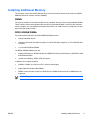
Installing Additional Memory .............................................................................................................. 17
DIMMs ............................................................................................................................... 17
DDR2-SDRAM DIMMs ...................................................................................................... 17
Populating DIMM Sockets ................................................................................................. 18
Installing DIMMs ................................................................................................................ 19
Removing or Installing an Expansion Card ........................................................................................ 21
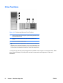
Drive Positions ................................................................................................................................... 26
Removing a Drive from a Drive Bay ................................................................................................... 27
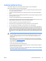
Installing Additional Drives ................................................................................................................. 29
Installing a 5.25-inch or 3.5-inch Drive into an External Drive Bay .................................... 30
Installing a 3.5-inch SATA Hard Drive into an Internal Drive Bay ...................................... 33
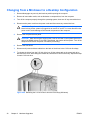
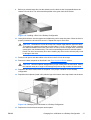
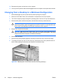
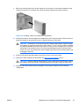
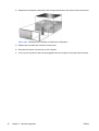
Changing from a Minitower to a Desktop Configuration ..................................................................... 36
Changing from a Desktop to a MinitowerConfiguration ...................................................................... 38
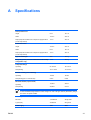
Appendix A Specifications
Appendix B Battery Replacement
ENWW v

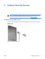
Appendix C External Security Devices
Installing a Security Lock .................................................................................................................... 47
Cable Lock ......................................................................................................................... 47
Padlock .............................................................................................................................. 48
Appendix D Electrostatic Discharge
Preventing Electrostatic Damage ....................................................................................................... 49
Grounding Methods ............................................................................................................................ 49
Appendix E Computer Operating Guidelines, Routine Care and Shipping Preparation
Computer Operating Guidelines and Routine Care ............................................................................ 51
Optical Drive Precautions ................................................................................................................... 52
Operation ........................................................................................................................... 52
Cleaning ............................................................................................................................. 52
Safety ................................................................................................................................. 52
Shipping Preparation .......................................................................................................................... 52
Index ................................................................................................................................................................... 53
vi ENWW

1 Product Features
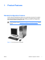
Standard Configuration Features
The HP Compaq Convertible Minitower features may vary depending on the model. For a complete
listing of the hardware and software installed in the computer, run the diagnostic utility (included on
some computer models only). Instructions for using the utility are provided in the Troubleshooting
Guide on the Documentation and Diagnostics CD.
NOTE The HP Compaq Convertible Minitower computer can be easily converted to a desktop.
For more information, see the
Changing from a Minitower to a Desktop Configuration section in
this guide.
Figure 1-1 Convertible Minitower Configuration
ENWW Standard Configuration Features 1

Front Panel Components
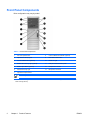
Drive configuration may vary by model.
Table 1-1 Front Panel Components
1 5.25-inch Optical Drives 8 5.25-inch Media Card Reader (optional)
2 Optical Drive Activity Lights 9 Dual-State Power Button
3 3.5-inch Diskette Drive (optional)
1
10 Power On Light
4 Diskette Drive Activity Light (optional) 11 USB (Universal Serial Bus) Ports
5 Diskette Eject Button (optional) 12 Headphone Connector
6 Hard Drive Activity Light 13 Microphone Connector
7 Optical Drive Eject Buttons
NOTE An optical drive is a CD-ROM, DVD+R/RW, or CD-RW/DVD Combo drive.
1
Some models are configured with a media card reader in the external 3.5-inch drive bay. Other models have a bezel
blank covering this bay.
2 Chapter 1 Product Features ENWW

Media Card Reader Components
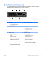
The media card reader is an optional device available on some models only. Refer to the following
illustration and table to identify the media card reader components.
Table 1-2 Media Card Reader Components
1 SmartMedia/xD
●
3.3V SmartMedia Card (SM)
●
D-Picture Card (xD)
4 USB (Universal Serial Bus) Port
2 Media Card Reader Activity Light 5 CompactFlash I/II
●
CompactFlash Card Type 1
●
CompactFlash Card Type 2
●
MicroDrive
3 SD/MMC+/miniSD
●
Secure Digital Card (SD)
●
MiniSD
●
MultiMediaCard (MMC)
●
Reduced Size MultiMediaCard (RS MMC)
●
MultiMediaCard 4.0 (Mobile Plus)
●
Reduced Size MultiMediaCard 4.0 (MMC
Mobile)
●
MMC Micro (adapter required)
●
MicroSD (T-Flash) (adapter required)
6 MS PRO/MS PRO DUO
●
Memory Stick (MS)
●
MagicGate Memory Stick (MG)
●
MagicGate Memory Duo
●
Memory Stick Select
●
Memory Stick Duo (MS Duo)
●
Memory Stick PRO (MS PRO)
●
Memory Stick PRO Duo (MS PRO Duo)
ENWW Media Card Reader Components 3

Rear Panel Components
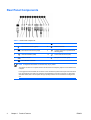
Table 1-3 Rear Panel Components
1 Power Cord Connector 7 Parallel Connector
2 PS/2 Mouse Connector (green) 8 Monitor Connector
3 PS/2 Keyboard Connector (purple) 9 Line-Out Connector for powered audio
devices (green)
4 Universal Serial Bus (USB) 10 Line-In Audio Connector (blue)
5 Serial Connector 11 Microphone Connector (pink)
6 RJ-45 Network Connector
NOTE Arrangement and number of connectors may vary by model.
The monitor connector on the system board is inactive when a PCI Express graphics card is installed in the
computer.
If a PCI graphics card is installed, the connectors on the card and the system board may be used at the same
time. Some settings may need to be changed in Computer Setup to use both connectors. For information
about Boot Order, refer to the Computer Setup (F10) Utility Guide on the Documentation and Diagnostics
CD.
4 Chapter 1 Product Features ENWW

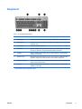
Keyboard
Table 1-4 Keyboard Components
1 Function Keys Perform special functions depending on the software application being used.
2 Editing Keys Includes the following: Insert, Home, Page Up, Delete, End, and Page Down.
3 Status Lights Indicate the status of the computer and keyboard settings (Num Lock, Caps Lock,
and Scroll Lock).
4 Numeric Keys Work like a calculator keypad.
5 Arrow Keys Used to navigate through a document or Web site. These keys allow you to move
left, right, up, and down, using the keyboard instead of the mouse.
6 Ctrl Keys Used in combination with another key; their effect depends on the application
software you are using.
7 Application Key
1
Used (like the right mouse button) to open pop-up menus in a Microsoft Office
application. May perform other functions in other software applications.
8 Windows Logo Keys
1
Used to open the Start menu in Microsoft Windows. Used in combination with other
keys to perform other functions.
9 Alt Keys Used in combination with another key; their effect depends on the application
software you are using.
1
Keys available in select geographic regions.
ENWW Keyboard 5

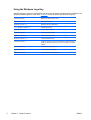
Using the Windows Logo Key
Use the Windows Logo key in combination with other keys to perform certain functions available in the
Windows operating system. Refer to the
Keyboard section to identify the Windows Logo key.
Windows Logo Key Displays or hides the Start menu
Windows Logo Key + d Displays the Desktop
Windows Logo Key + m Minimizes all open applications
Shift + Windows Logo Key + m Undoes Minimize All
Windows Logo Key + e Launches My Computer
Windows Logo Key + f Launches Find Document
Windows Logo Key + Ctrl + f Launches Find Computer
Windows Logo Key + F1 Launches Windows Help
Windows Logo Key + l Locks the computer if you are connected to a network domain, or
allows you to switch users if you are not connected to a network
domain
Windows Logo Key + r Launches the Run dialog box
Windows Logo Key + u Launches the Utility Manager
Windows Logo Key + Tab Activates the next Taskbar button
6 Chapter 1 Product Features ENWW

Special Mouse Functions
Most software applications support the use of a mouse. The functions assigned to each mouse button
depend on the software applications you are using.
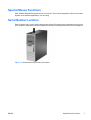
Serial Number Location
Each computer has a unique serial number and a product ID number that are located on the top cover
of the computer. Keep these numbers available for use when contacting customer service for assistance.
Figure 1-2 Serial Number and Product ID Location
ENWW Special Mouse Functions 7

8 Chapter 1 Product Features ENWW

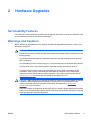
2 Hardware Upgrades
Serviceability Features
The computer includes features that make it easy to upgrade and service. No tools are needed for most
of the installation procedures described in this chapter.
Warnings and Cautions
Before performing upgrades be sure to carefully read all of the applicable instructions, cautions, and
warnings in this guide.
WARNING! To reduce the risk of personal injury from electrical shock, hot surfaces, or fire:
Disconnect the power cord from the wall outlet and allow the internal system components to cool
before touching.
Do not plug telecommunications or telephone connectors into the network interface controller
(NIC) receptacles.
Do not disable the power cord grounding plug. The grounding plug is an important safety feature.
Plug the power cord in a grounded (earthed) outlet that is easily accessible at all times.
To reduce the risk of serious injury, read the Safety & Comfort Guide. It describes proper
workstation, setup, posture, and health and work habits for computer users, and provides
important electrical and mechanical safety information. This guide is located on the Web at
http://www.hp.com/ergo and on the Documentation and Diagnostics CD.
CAUTION Static electricity can damage the electrical components of the computer or optional
equipment. Before beginning these procedures, ensure that you are discharged of static
electricity by briefly touching a grounded metal object. See Appendix D,
Electrostatic
Discharge for more information.
When the computer is plugged into an AC power source, voltage is always applied to the system
board. You must disconnect the power cord from the power source before opening the computer
to prevent damage to internal components.
ENWW Serviceability Features 9

Unlocking the Smart Cover Lock
NOTE The Smart Cover Lock is an optional feature included on some models only.
The Smart Cover Lock is a software-controllable cover lock, controlled by the setup password. This lock
prevents unauthorized access to the internal components. The computer ships with the Smart Cover
Lock in the unlocked position. For more information about locking the Smart Cover Lock, refer to the
Desktop Management Guide on the Documentation and Diagnostics CD.
Smart Cover FailSafe Key
If you enable the Smart Cover Lock and cannot enter your password to disable the lock, you will need
a Smart Cover FailSafe Key to open the computer cover. You will need the key to access the internal
computer components in any of the following circumstances:
●
Power outage
●
Startup failure
●
PC component (for example, processor or power supply) failure
●
Forgotten password
NOTE The Smart Cover FailSafe Key is a specialized tool available from HP. Be prepared;
order this key before you need one.
To obtain a FailSafe Key:
●
Contact an authorized HP reseller or service provider. Order PN 166527-001 for the wrench-style
key or PN 166527-002 for the screwdriver bit key.
●
Refer to the HP Web site (
http://www.hp.com) for ordering information.
●
Call the appropriate number listed in the warranty or in the Support Telephone Numbers guide on
the Documentation and Diagnostics CD.
Using the Smart Cover FailSafe Key to Remove the Smart Cover Lock
To open the access panel with the Smart Cover Lock engaged:
1. Remove/disengage any security devices that prohibit opening the computer.
2. Remove all removable media, such as diskettes or compact discs, from the computer.
3. Turn off the computer properly through the operating system, then turn off any external devices.
4. Disconnect the power cord from the power outlet and disconnect any external devices.
CAUTION Regardless of the power-on state, voltage is always present on the system
board as long as the system is plugged into an active AC outlet. You must disconnect the
power cord to avoid damage to the internal components of the computer.
10 Chapter 2 Hardware Upgrades ENWW

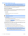
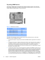
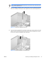
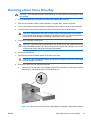
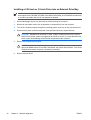
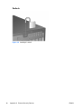
5. Use the Smart Cover FailSafe Key to remove the two tamper-proof screws that secure the Smart
Cover Lock to the chassis.
Figure 2-1 Removing the Smart Cover Lock Screws
6. Remove the access panel.
To reattach the Smart Cover Lock, secure the lock in place with the tamper-proof screws.
ENWW Unlocking the Smart Cover Lock 11

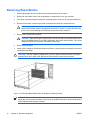
Removing the Computer Access Panel
1. Remove/disengage any security devices that prohibit opening the computer.
2. Remove all removable media, such as diskettes or compact discs, from the computer.
3. Turn off the computer properly through the operating system, then turn off any external devices.
4. Disconnect the power cord from the power outlet and disconnect any external devices.
CAUTION Regardless of the power-on state, voltage is always present on the system
board as long as the system is plugged into an active AC outlet. You must disconnect the
power cord to avoid damage to the internal components of the computer.
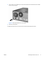
5. Lay the computer down on its large base for greater stability.
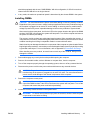
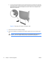
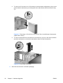
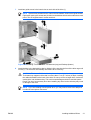
6. Lift up on the access panel handle (1), slide the access panel back about 1.25 cm (1/2 inch), then
lift it up and off the unit (2).
Figure 2-2 Removing the Computer Access Panel
CAUTION After removing the access panel, look for the LED on the system board to the
right of the DIMM sockets. If the LED is illuminated, the system still has power. Turn off the
computer and remove the power cord before proceeding.
12 Chapter 2 Hardware Upgrades ENWW

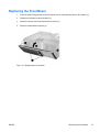
Replacing the Computer Access Panel
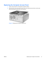
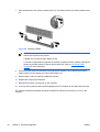
1. Lay the computer down on its large base for greater stability.
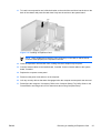
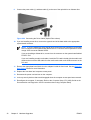
2. Align the tabs on the access panel with the slots on the chassis and push down on the access
panel while sliding it forward until it locks into place.
Figure 2-3 Replacing the Computer Access Panel
ENWW Replacing the Computer Access Panel 13

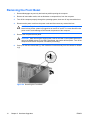
Removing the Front Bezel
1. Remove/disengage any security devices that prohibit opening the computer.
2. Remove all removable media, such as diskettes or compact discs, from the computer.
3. Turn off the computer properly through the operating system, then turn off any external devices.
4. Disconnect the power cord from the power outlet and disconnect any external devices.
CAUTION Regardless of the power-on state, voltage is always present on the system
board as long as the system is plugged into an active AC outlet. You must disconnect the
power cord to avoid damage to the internal components of the computer.
5. Remove the computer access panel.
CAUTION After removing the access panel, look for the LED on the system board to the
right of the DIMM sockets. If the LED is illuminated, the system still has power. Turn off the
computer and remove the power cord before proceeding.
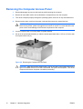
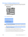
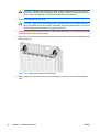
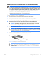
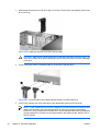
6. Push up on the two release tabs (1), then rotate the front bezel away from the chassis to release
it (2).
Figure 2-4 Removing the Front Bezel
14 Chapter 2 Hardware Upgrades ENWW
Page is loading ...
Page is loading ...
Page is loading ...
Page is loading ...
Page is loading ...
Page is loading ...
Page is loading ...
Page is loading ...
Page is loading ...
Page is loading ...
Page is loading ...
Page is loading ...
Page is loading ...
Page is loading ...
Page is loading ...
Page is loading ...
Page is loading ...
Page is loading ...
Page is loading ...
Page is loading ...
Page is loading ...
Page is loading ...
Page is loading ...
Page is loading ...
Page is loading ...
Page is loading ...
Page is loading ...
Page is loading ...
Page is loading ...
Page is loading ...
Page is loading ...
Page is loading ...
Page is loading ...
Page is loading ...
Page is loading ...
Page is loading ...
Page is loading ...
Page is loading ...
Page is loading ...
Page is loading ...
-
 1
1
-
 2
2
-
 3
3
-
 4
4
-
 5
5
-
 6
6
-
 7
7
-
 8
8
-
 9
9
-
 10
10
-
 11
11
-
 12
12
-
 13
13
-
 14
14
-
 15
15
-
 16
16
-
 17
17
-
 18
18
-
 19
19
-
 20
20
-
 21
21
-
 22
22
-
 23
23
-
 24
24
-
 25
25
-
 26
26
-
 27
27
-
 28
28
-
 29
29
-
 30
30
-
 31
31
-
 32
32
-
 33
33
-
 34
34
-
 35
35
-
 36
36
-
 37
37
-
 38
38
-
 39
39
-
 40
40
-
 41
41
-
 42
42
-
 43
43
-
 44
44
-
 45
45
-
 46
46
-
 47
47
-
 48
48
-
 49
49
-
 50
50
-
 51
51
-
 52
52
-
 53
53
-
 54
54
-
 55
55
-
 56
56
-
 57
57
-
 58
58
-
 59
59
-
 60
60


Ask a question and I''ll find the answer in the document
Finding information in a document is now easier with AI
Related papers
-
Compaq dc7800 Series Reference guide
-
HP EliteDesk 705 G4 Workstation Edition Reference guide
-
HP dc72 Base Model Blade Workstation Client User manual
-
-
-
HP dc73 Blade Workstation Client Reference guide
-
HP Compaq dc7700 SFF Reference guide
-
HP Compaq dc5800 Reference guide
-
HP EliteDesk 800 G3 Tower PC (ENERGY STAR) Reference guide
-
HP Compaq dc7600 Convertible Minitower PC Reference guide
Other documents
-
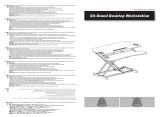 EleTab Height Adjustable Standing Desk Sit to Stand Gas Spring Riser Converter 37 inches Tabletop Workstation fits Dual Monitor User manual
-
DeLOCK 91693 Datasheet
-
Compaq Compaq dx2390 Microtower Hardware Reference Manual
-
-
Centon TAA133PC512.01 Installation guide
-
-
-
-
-
